Lincoln Navigator: Engine - 3.5L EcoBoost (272kW/370PS) / Oil Pan. Removal and Installation
Special Tool(s) /
General Equipment
| Plastic Scraper |
| Oil Drain Equipment |
| Vehicle/Axle Stands |
Materials
| Name |
Specification |
Motorcraft® High Performance Engine RTV Silicone
TA-357 |
WSE-M4G323-A6
|
Motorcraft® Silicone Gasket Remover
ZC-30-A, AZC-30-C |
-
|
Motorcraft® Metal Surface Prep Wipes
ZC-31-B |
-
|
Motorcraft® Metal Brake Parts Cleaner
PM-4-A, PM-4-B, APM-4-C |
-
|
Removal
NOTICE:
During engine repair procedures, cleanliness is extremely
important. Any foreign material, including any material created while
cleaning gasket surfaces, that enters the oil passages, coolant passages
or the oil pan, may cause engine failure.
4x2/4x4
-
With the vehicle in NEUTRAL, position it on a hoist.
Refer to: Jacking and Lifting (100-02 Jacking and Lifting, Description and Operation).
-
Disconnect the battery ground cable.
Refer to: Battery Disconnect and Connect (414-01 Battery, Mounting and Cables, General Procedures).
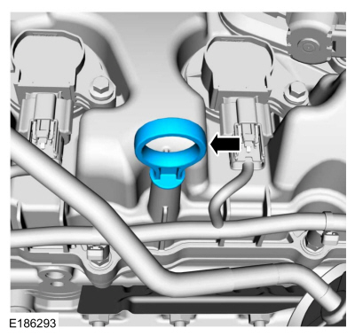
-
Remove the oil level indicator.
-
-
If equipped.
Remove the bolts.
-
Release the retainer and remove the transmission housing cover.
-
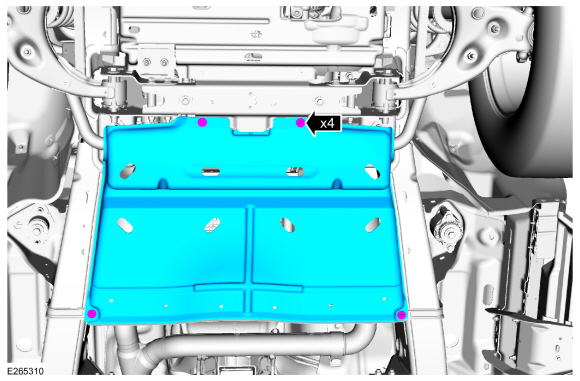
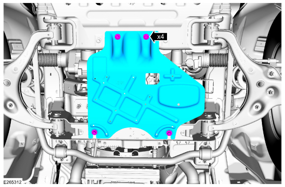
NOTE:
Vehicles come with an underbody shield or a skid plate.
-
If equipped.
Remove the pin-type retainers.
-
Remove the bolts and the underbody shield.
-
If equipped.
Remove the bolts and the skid plate.
-
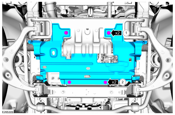
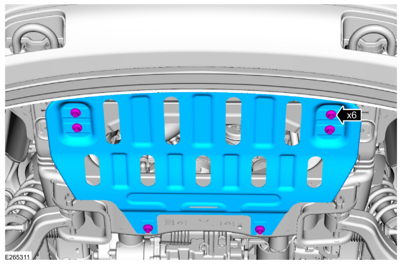
NOTE:
Vehicles come with an underbody shield or a skid plate.
If equipped.
Remove the bolts and the skid plate.
-
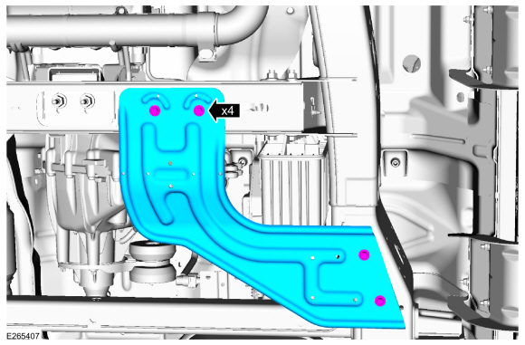
If equipped.
Remove the bolts and the skid plate.
-
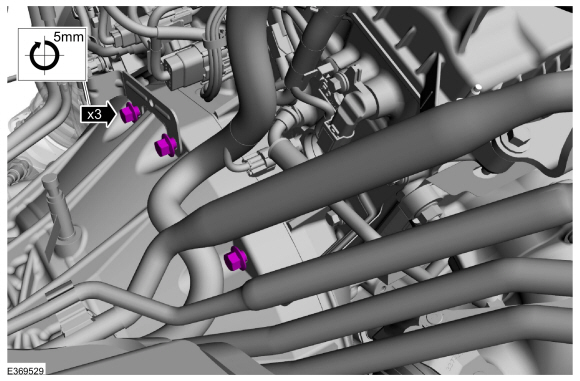
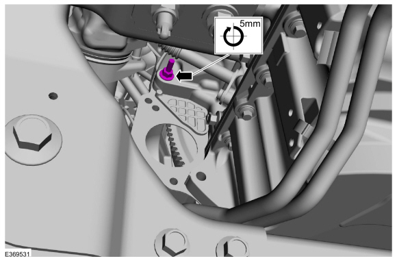
Loosen the upper bellhousing bolts 5 mm (0.19 in).
-
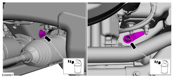
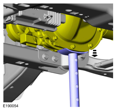
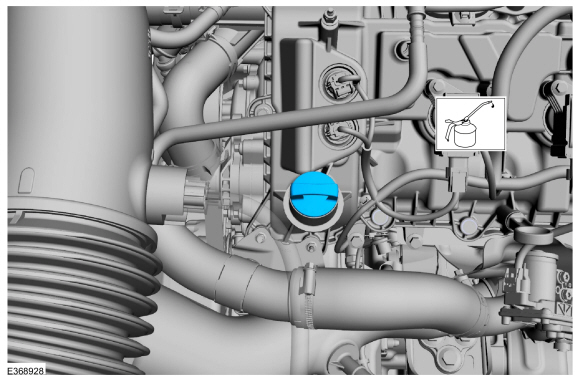
Remove the oil pan plug and drain the engine oil.
Use the General Equipment: Oil Drain Equipment
Torque:
20 lb.ft (27 Nm)
-
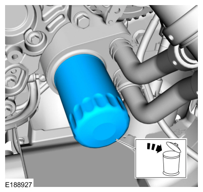
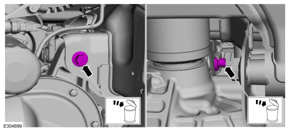
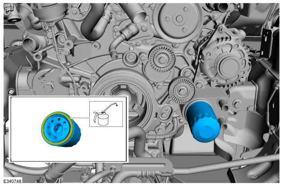
Remove and discard the oil filter.
Use the General Equipment: Oil Drain Equipment
-
Remove the starter.
Refer to: Starter Motor (303-06 Starting System - 3.5L EcoBoost (272kW/370PS), Removal and Installation).
-
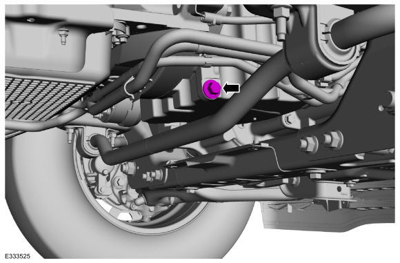
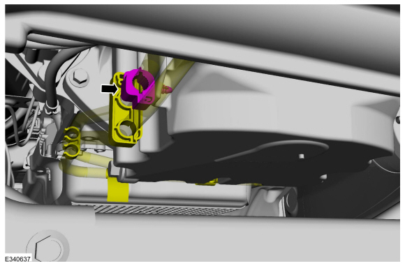
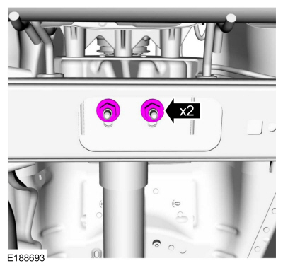
Remove the nut and position the cooler tubes aside.
-
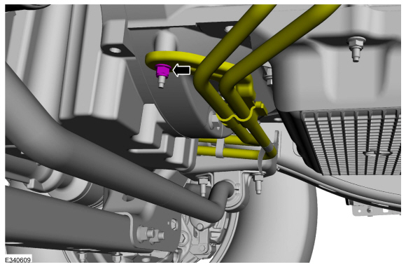
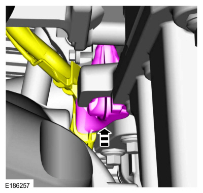
Remove the pin-type retainerand position the cooler tube out.
-
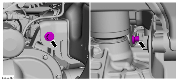
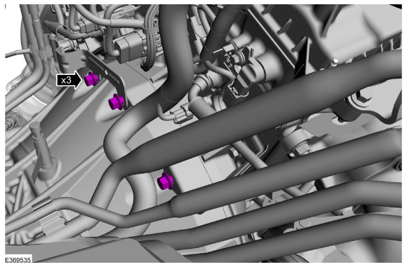
Remove the pin-type retainer and position the cooler tubes from the oil pan.
-
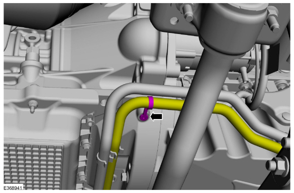
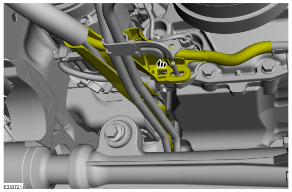
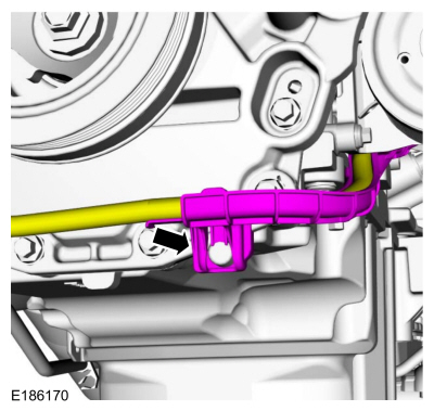
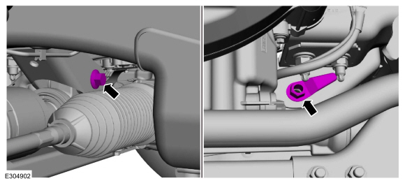
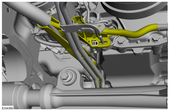
Remove the pin-type retainers. Position the wiring harness and transmission tube from the oil pan.
-
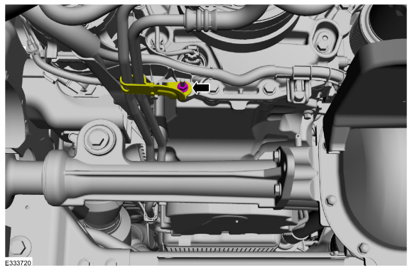
Remove the nut and position out the transmission cooler tube bracket.
-
Position out the engine wiring harness.
-
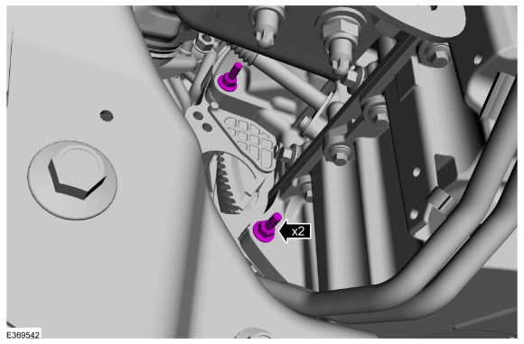
Detach the generator wiring harness from the engine front cover.
-
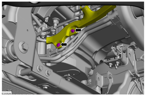
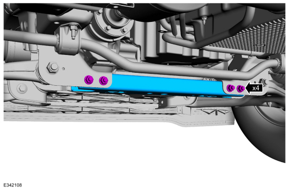
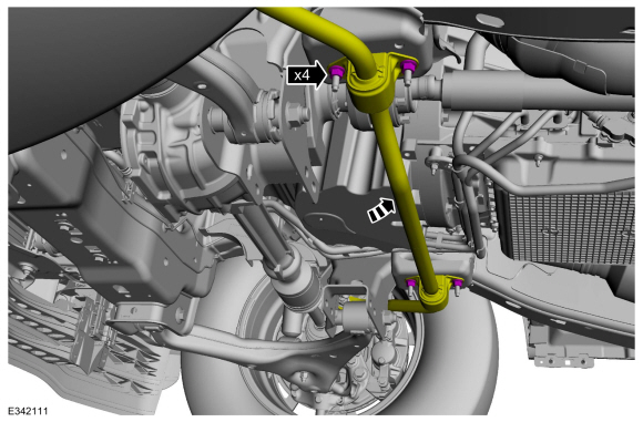
Remove the nuts, bolts and the crossmember.
-
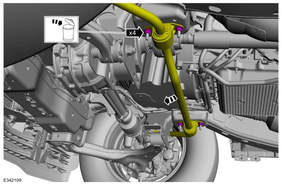
Remove and discard the nuts, allow the sway bar to swing downward.
4x4
-
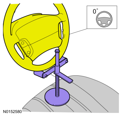
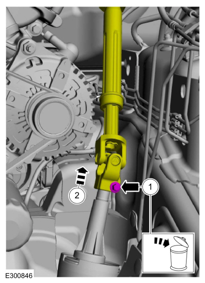
Using a holding device, hold the steering wheel in the straight-ahead position.
-
-
 WARNING:
Install a new steering column shaft bolt.
Reuse could result in bolt failure and loss of vehicle control. Failure
to follow this instruction may result in serious injury to vehicle
occupant(s).
WARNING:
Install a new steering column shaft bolt.
Reuse could result in bolt failure and loss of vehicle control. Failure
to follow this instruction may result in serious injury to vehicle
occupant(s).
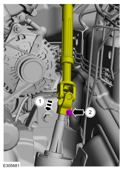
Remove and discard the steering column shaft bolt.
-
Separate the steering column shaft U-joint from the steering gear.
-
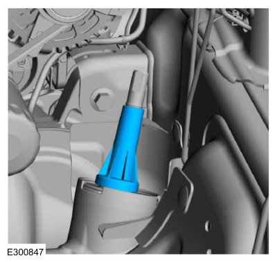
Remove the steering gear boot.
-
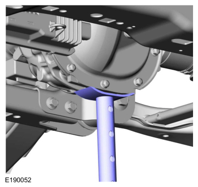
Using an adjustable stand, support the front axle.
Use the General Equipment: Vehicle/Axle Stands
-
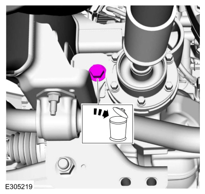
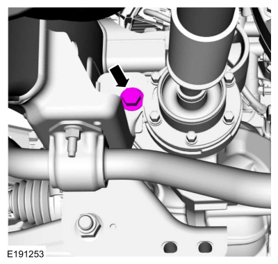
Remove and discard the lower front axle carrier mounting bushing bolt.
-
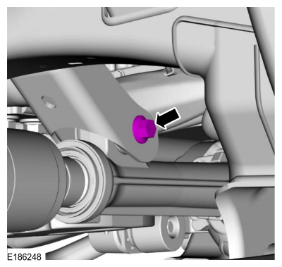
Remove and discard the axle shaft housing carrier bushing nut and the bolt.
-
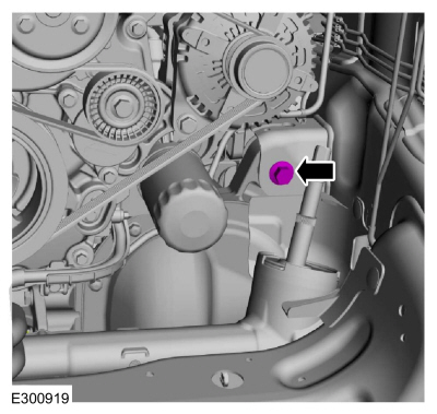
NOTE:
After loosening the bolt, it may be necessary to
reposition the axle assembly to prevent interference with the steering
components when removing the bolt.
Remove and discard the upper front axle carrier mounting bushing nut and the bolt.
-
Using an adjustable stand, lower the axle to allow clearance for the oil pan to be removed.
Use the General Equipment: Vehicle/Axle Stands
4x2/4x4
-
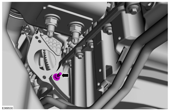
Remove the oil pan stud.
-
Loosen the bellhousing stud 5 mm (0.19 in).
-
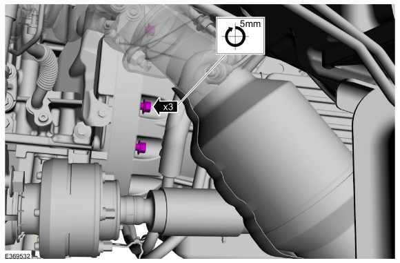
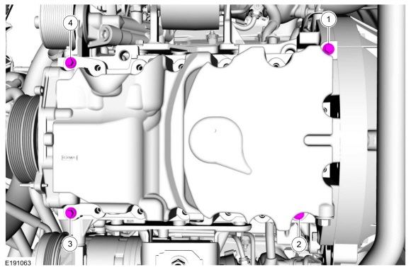
Remove the oil pan bolts.
-
Loosen the bellhousing bolts 5 mm (0.19 in).
-
NOTICE:
Only use hand tools when removing the
transmission mount-to-crossmember nuts or damage to the transmission
mount can occur.
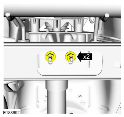
Loosen the transmission mount-to-crossmenber nuts.
-
Separate the engine and transmission 5 mm (0.19 in).
-
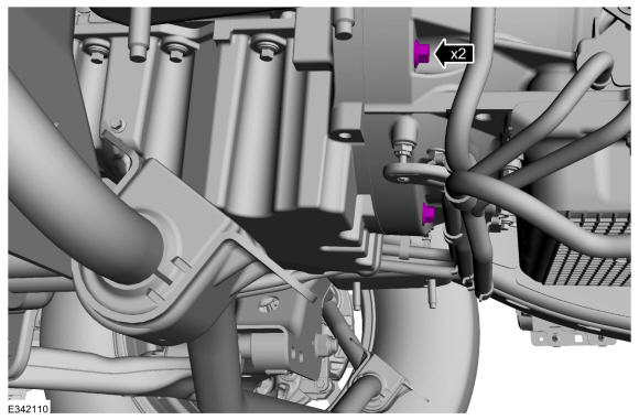
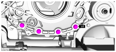
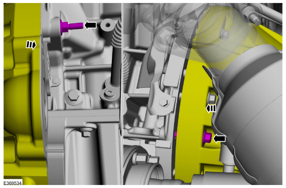
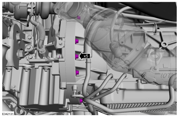
Remove the engine front cover bolts.
-
Remove the oil pan bolts.
-
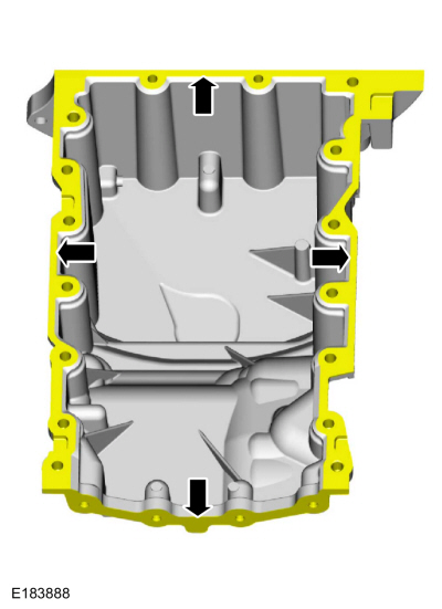
NOTE:
RH shown, LH similar.
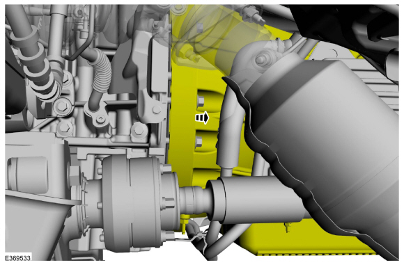
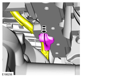
Using a pry tool on the pry pads, remove the oil pan.
-
NOTE:
The generator wiring harness retainer is being removed for clearance to install the oil pan.
Detach the generator wiring harness retainer from the engine block.
-
NOTICE:
Only use a 3M™ Roloc® Bristle Disk (2-in white,
part number 07528) to clean the oil pan and engine front cover. Do not
use metal scrapers, wire brushes or any other power abrasive disk to
clean. These tools cause scratches and gouges that make leak paths.
-
Make sure that the mating faces of the oil pan
and engine front cover are clean and free of foreign material.
Material: Motorcraft® Silicone Gasket Remover
/ ZC-30-A, AZC-30-C
Material: Motorcraft® Metal Surface Prep Wipes
/ ZC-31-B
-
Thoroughly wash the oil pan to remove any
foreign material, including any abrasive particles created during the
cleaning process.
 |
|
-
NOTICE:
Do not use wire brushes, power abrasive discs or
3M™ Roloc® Bristle Disk (2-in white, part number 07528) to clean the
sealing surfaces of the engine block. These tools cause scratches and
gouges that make leak paths. They also cause contamination that causes
premature engine failure. Remove all traces of the gasket.
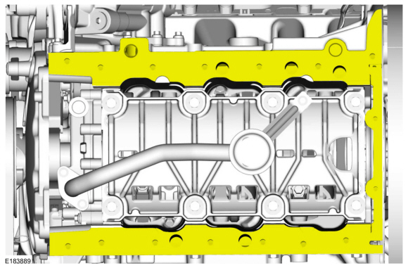
Make sure that the mating faces of the engine block are clean and free of foreign material.
Refer to: RTV Sealing Surface Cleaning and Preparation (303-00 Engine System - General Information, General Procedures).
Use the General Equipment: Plastic Scraper
Material: Motorcraft® Silicone Gasket Remover
/ ZC-30-A, AZC-30-C
Material: Motorcraft® Metal Surface Prep Wipes
/ ZC-31-B
Material: Motorcraft® Metal Brake Parts Cleaner
/ PM-4-A, PM-4-B, APM-4-C
-
Make sure that the mating faces of the engine front cover are clean and free of foreign material.
Refer to: RTV Sealing Surface Cleaning and Preparation (303-00 Engine System - General Information, General Procedures).
Installation
4x2/4x4
NOTICE:
Failure to use Motorcraft® High Performance Engine RTV
Silicone may cause the engine oil to foam excessively and result in
serious engine damage.
-
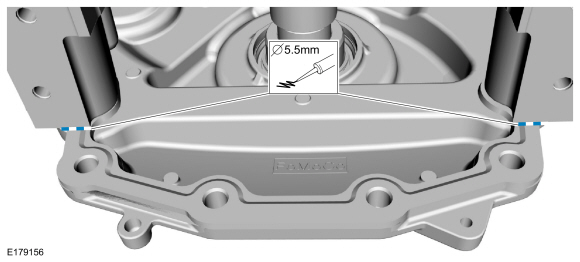
Apply a 5.5 mm (0.21 in) bead of Motorcraft® High
Performance Engine RTV Silicone to the 2 crankshaft engine front
cover-to-cylinder block joint areas.
Material: Motorcraft® High Performance Engine RTV Silicone
/ TA-357
(WSE-M4G323-A6)
-
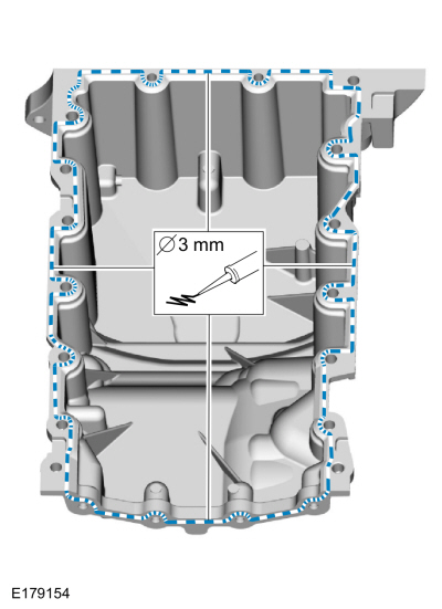
NOTE:
The oil pan and the specified bolts must be
installed and the oil pan aligned to the cylinder block within 4 minutes
of sealant application. Final tightening of the oil pan bolts must be
carried out within 60 minutes of sealant application.
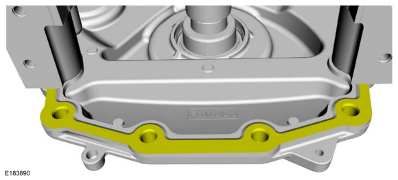
Apply a 3 mm (0.11 in) bead of Motorcraft® High
Performance Engine RTV Silicone to the sealing surface of the oil pan.
Material: Motorcraft® High Performance Engine RTV Silicone
/ TA-357
(WSE-M4G323-A6)
-
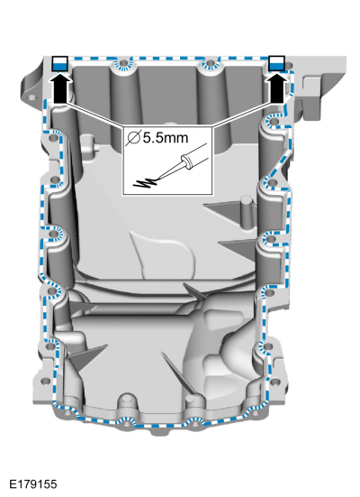
Apply a 5.5 mm (0.21 in) bead of Motorcraft® High
Performance Engine RTV Silicone to the 2 crankshaft seal retainer
plate-to-cylinder block joint areas on the sealing surface of the oil
pan.
Material: Motorcraft® High Performance Engine RTV Silicone
/ TA-357
(WSE-M4G323-A6)
-
NOTE:
The oil pan and the specified bolts must be
installed within 4 minutes of the start of sealant application.
NOTE:
Keep the oil pan as close as possible to the
transmission while installing, then slide forward towards the engine
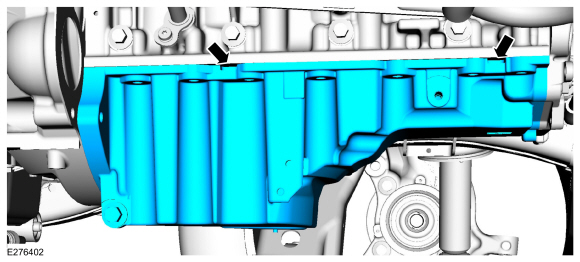
front cover to prevent wiping off of the sealant.
Install the oil pan and the bolts finger tight.
-
NOTE:
Do not torque at this time.
Draw the transmission and engine together using the bolts.
-
NOTE:
Do not torque at this time.
Install the oil pan bolts.
-
NOTE:
Do not torque at this time.
Install the oil pan stud.
-
Tighten the oil pan bolts.
Torque:
27 lb.in (3 Nm)
-
Install the engine front cover bolts finger tight.
-
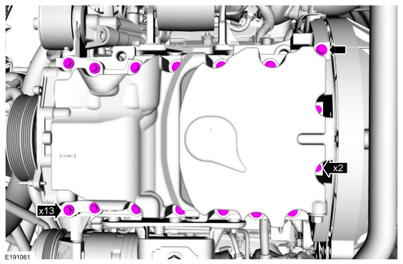
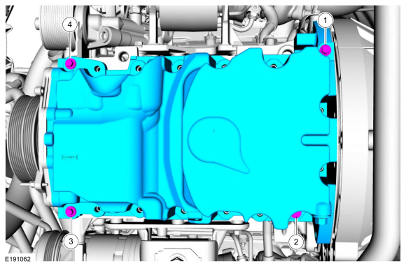
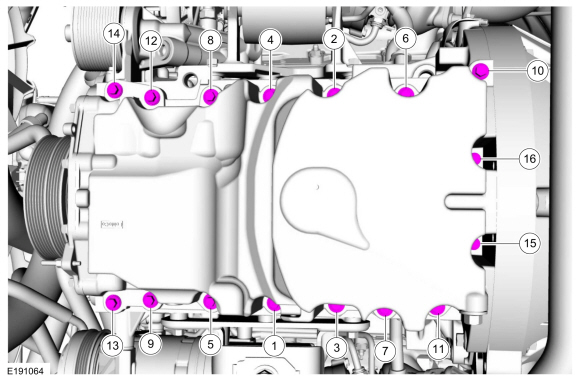
Install the remaining oil pan bolts and tighten in sequence.
Torque:
Stage 1:
Tighten bolts 1-9 and 11-14 to :
177 lb.in (20 Nm)
Stage 2:
Tighten bolt 1-9 and 11-14 additional :
45°
Stage 3:
Tighten bolt 10 to :
177 lb.in (20 Nm)
Stage 4:
Tighten bolt 10 an additional :
45°
Stage 5:
Tighten bolts 15 and 16 to :
89 lb.in (10 Nm)
Stage 6:
Tighten bolts 15 and 16 an additional :
90°
-
Tighten the engine front cover bolts.
Torque:
18 lb.ft (24 Nm)
-
Tighten the oil pan and bellhousing bolts.
Torque:
35 lb.ft (48 Nm)
-
Tighten the oil pan and bellhousing bolts.
Torque:
35 lb.ft (48 Nm)
-
Remove and discard the transmission
mount-to-crossmember nuts. Install new transmission mount-to-crossmember
nuts.
Torque:
85 lb.ft (115 Nm)
-
Attach the generator wiring harness retainer to the engine block.
4x4
-
NOTICE:
Use care when positioning the front axle housing
or the vacuum lines to the axle solenoid may become disconnected or
damaged.
Using an adjustable stand, raise the front axle carrier into position.
Use the General Equipment: Vehicle/Axle Stands
-
NOTE:
It may be necessary to reposition the axle
assembly to prevent interference with the steering components when
installing the bolt.
Install the new upper front axle carrier mounting bushing nut and the bolt finger tight.
-
Install the new axle shaft housing carrier bushing nut and the bolt finger tight.
-
Install the new lower front axle carrier mounting bushing bolt.
Torque:
129 lb.ft (175 Nm)
-
Tighten the axle shaft housing carrier bushing bolt.
Torque:
129 lb.ft (175 Nm)
-
Tighten the upper front axle carrier mounting bushing bolt.
Torque:
129 lb.ft (175 Nm)
-
Remove the adjustable stand.
Use the General Equipment: Vehicle/Axle Stands
-
Install the steering gear boot.
-
-
Position back the steering column shaft U-joint to the steering gear.
-
WARNING:
Install a new steering column shaft bolt.
Reuse could result in bolt failure and loss of vehicle control. Failure
to follow this instruction may result in serious injury to vehicle
occupant(s).
Install a new steering column shaft bolt.
Torque:
22 lb.ft (30 Nm)
-
Remove the holding device from the steering wheel.
4x2/4x4
-
Attach the generator wiring harness to the engine front cover.
-
Position back the engine wiring harness.
-
Position back the engine wire harness. Position back
the transmission cooler tube bracket and install the nut.
Torque:
106 lb.in (12 Nm)
-
Position the wiring harness cover to the oil pan and install the fasteners.
Torque:
18 lb.ft (25 Nm)
-
Position the cooler tubes to the oil pan and install the pin-type retainer.
-
Install the pin-type retainer position the cooler tube back.
-
Position the cooler tubes back and install the nut.
Torque:
124 lb.in (14 Nm)
-
Position the sway bar back and install the nuts.
Torque:
41 lb.ft (55 Nm)
-
Position the crossmember, install the nuts and bolts.
Torque:
66 lb.ft (90 Nm)
-
Install the starter motor.
Refer to: Starter Motor (303-06 Starting System - 3.5L EcoBoost (272kW/370PS), Removal and Installation).
-
Install a new oil filter.
Torque:
Stage 1:
44 lb.in (5 Nm)
Stage 2:
180°
-
Tighten the upper bell housing-to-engine bolts.
Torque:
35 lb.ft (48 Nm)
-
If equipped.
Install the skid plate and the bolts.
Torque:
30 lb.ft (40 Nm)
-
NOTE:
Vehicles come with an underbody shield or a skid plate.
If equipped.
Install the skid plate and the bolts.
Torque:
30 lb.ft (40 Nm)
-
NOTE:
Vehicles come with an underbody shield or a skid plate.
If equipped.
Install the skid plate and the bolts.
Torque:
30 lb.ft (40 Nm)
-
-
If equipped.
Install the underbody shield and the bolts.
Torque:
30 lb.ft (40 Nm)
-
Install the bolts.
Torque:
71 lb.in (8 Nm)
-
If equipped.
Install the transmission housing cover and install the bolts.
Torque:
71 lb.in (8 Nm)
-
Install the oil level indicator.
-
Fill the engine with clean engine oil.
Refer to: Specifications (303-01)
.
-
Connect the battery ground cable.
Refer to: Battery Disconnect and Connect (414-01 Battery, Mounting and Cables, General Procedures).
-
Fill and bleed the cooling system.
Refer to: Engine Cooling System Draining, Vacuum Filling and Bleeding
(303-03 Engine Cooling - 3.5L EcoBoost (272kW/370PS), General
Procedures).
Special Tool(s) /
General Equipment
Oil Drain Equipment
Hose Clamp Remover/Installer
Locking Pliers
Removal
With the vehicle in NEUTRAL, position it on a hoist...
Special Tool(s) /
General Equipment
303-1655Tool, Camshaft Holding
Vehicle/Axle Stands
Materials
Name
Specification
Motorcraft® High Performance Engine RTV SiliconeTA-357
WSE-M4G323-A6
Removal
NOTICE:
During engine repair procedures, cleanliness is extremely
important...
Other information:
System Operation
Overview - Active Park Assist
NOTE:
Vehicles equipped with active park assist use a different parking aid
sensor. The IPMA supplies a 12v reference voltage and a ground. The
signal circuit is a LIN used to comunicate the sensor data with the IPMA
...
Removal
Remove the main control valve body.
Refer to: Main Control Valve Body (307-01 Automatic Transmission -
10-Speed Automatic Transmission – 10R80, Removal and Installation).
Remove the TSS sensor.
Slide the plastic lock to the unlocked position...

 Oil Cooler. Removal and Installation
 Oil Pump. Removal and Installation