Lincoln Navigator: Lane Keeping System / Lane Keeping System - Component Location. Description and Operation
Component Location - Lane Keeping System
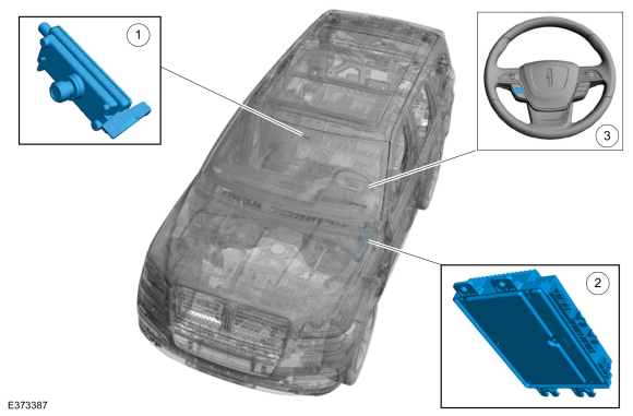
| Item | Description |
|---|---|
| 1 | IPMA camera |
| 2 | IPMA |
| 3 | Lane keeping system switch |

 Lane Keeping System - Overview. Description and Operation
Overview
The
lane keeping system has 3 operating modes to help the driver stay
within their lane, lane keeping aid, lane keeping alert and a
combination of both the lane keeping aid and lane keeping alert...
Other information:
Lincoln Navigator 2018-2026 Workshop Manual: Transmission Fluid Pump Idler Gear. Removal and Installation
Special Tool(s) / General Equipment 205-1018Installation Tube 307-003 (T57L-500-B) Holding Fixture, Transmission 307-091Handle, Torque ConverterTKIT-2009TC-F 307-346 (T97T-7902-A) Retainer, Torque ConverterTKIT-1998-LM (NavigatoR)TKIT-1997-F/FLM/LT 307-736Installer, Pump Drive Gear Bearing 307-737Press Tool, Oil Pump Drive ..
Lincoln Navigator 2018-2026 Workshop Manual: Exhaust Manifold RH. Removal and Installation
Materials Name Specification Motorcraft® Metal Surface Prep WipesZC-31-B - Removal With the vehicle in NEUTRAL, position it on a hoist. Refer to: Jacking and Lifting (100-02 Jacking and Lifting, Description and Operation). NOTICE: The exhaust manifold heat shield provides critical protection for dual generator-equip..
Categories
- Manuals Home
- 4th Gen Lincoln Navigator Service Manual (2018 - 2026)
- Identification Codes. Description and Operation
- Transmission Fluid Drain and Refill. General Procedures
- SYNC Module [APIM]. Removal and Installation
- Brake Service Mode Activation and Deactivation. General Procedures
- Vehicle Dynamics Control Module (VDM). Removal and Installation
Wheel to Hub Runout Minimization. General Procedures
Check
NOTE: Wheel-to-hub optimization is important. Clearance between the wheel and hub can be used to offset or neutralize the Road Force® or run-out of the wheel and tire assembly. For every 0.001 inch of wheel-to-hub clearance, the Road Force® can be affected between 1 and 3 pounds depending on the tire stiffness.
NOTE: The example below illustrates how the clearance between the wheel and the hub can be used to offset the high spot of radial run-out or Road Force®. Following the procedure will make sure of the best optimization.
Position the wheel and tire assembly on the vehicle so that the high spot location of radial run-out or Road Force® is at the 6 o'clock position and