Lincoln Navigator: Engine - 3.5L EcoBoost (272kW/370PS) / Cylinder Head RH. Removal and Installation
Special Tool(s) /
General Equipment
Materials
| Name |
Specification |
Motorcraft® Silicone Gasket Remover
ZC-30-A, AZC-30-C |
-
|
Motorcraft® Metal Surface Prep Wipes
ZC-31-B |
-
|
Removal
NOTICE:
During engine repair procedures, cleanliness is extremely
important. Any foreign material, including any material created while
cleaning gasket surfaces that enters the oil passages, coolant passages
or the oil pan, can cause engine failure.
-
With the vehicle in NEUTRAL, position it on a hoist.
Refer to: Jacking and Lifting (100-02 Jacking and Lifting, Description and Operation).
-
Release the fuel system pressure.
Refer to: Fuel System Pressure Release (310-00 Fuel System - General
Information - 3.5L EcoBoost (272kW/370PS), General Procedures).
-
Disconnect the battery ground cable.
Refer to: Battery Cables (414-01 Battery, Mounting and Cables, Removal and Installation).
-
Remove the EGR cooler.
Refer to: Exhaust Gas Recirculation (EGR) Cooler (303-08 Engine
Emission Control - 3.5L EcoBoost (272kW/370PS), Removal and
Installation).
-
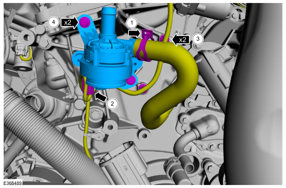
-
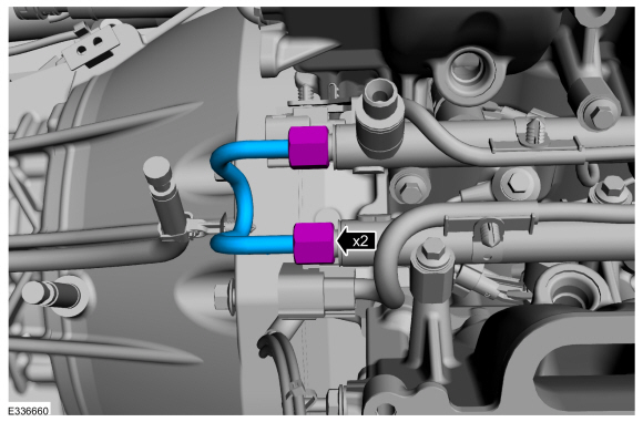
Disconnect the heater hose.
-
Disconnect the electrical connector.
-
Disconnect the pin-type retainer.
-
Remove the bolts and the cabin heater pump.
-
Remove the RH turbocharger.
Refer to: Turbocharger RH (303-04B Fuel Charging and Controls -
Turbocharger - 3.5L EcoBoost (272kW/370PS), Removal and Installation).
-
Remove the RH camshaft.
Refer to: Camshaft RH (303-01 Engine - 3.5L EcoBoost (272kW/370PS), Removal and Installation).
-
Remove the port injection fuel rail.
Refer to: Port Injection Fuel Rail (303-04A Fuel Charging and Controls -
3.5L EcoBoost (272kW/370PS), Removal and Installation).
-
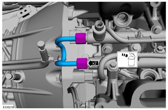
Remove and discard the fuel rail-to-fuel rail high-pressure tube.
-
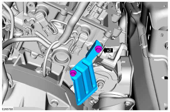
Remove the retainers and the heat shield.
-
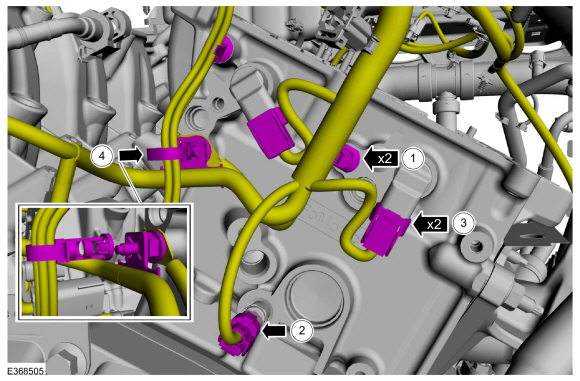
-
Disconnect the CHT sensor electrical connector.
-
Disconnect the CMP sensor electrical connectors.
-
Position aside wire retainer. Remove the studbolt and the ground wire.
-
Disconnect the pin-type retainer.
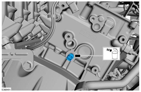
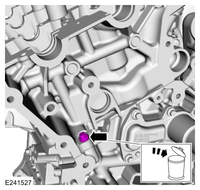
-
Remove and discard the CHT sensor.
-
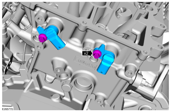
Remove the bolts and the CMP sensors.
-
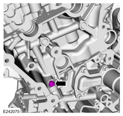
Remove and discard the RH M6 bolt.
-
NOTICE:
Place clean shop towels over exposed engine
cavities. Carefully remove the towels so foreign material is not dropped
into the engine. Any foreign material (including any material created
while cleaning gasket surfaces) that enters the oil passages or the oil
pan, may cause engine failure.
NOTICE:
Aluminum surfaces are soft and can be scratched
easily. Never place the cylinder head gasket surface, unprotected, on a
bench surface
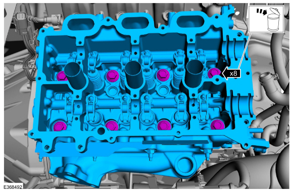
NOTE:
The cylinder head bolts must be discarded and new
bolts must be installed. They are tighten-to-yield designed and cannot
be reused.
-
Remove and discard the bolts from the RH cylinder head.
-
Remove the cylinder head.
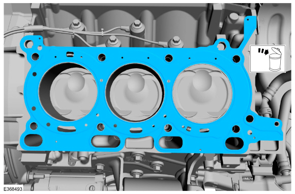
-
Remove and discard the RH cylinder head gasket.
-
Remove the RH water jacket spacer.
Use the General Equipment: Long Nose Pliers
-
NOTICE:
Do not use metal scrapers, wire brushes, power
abrasive discs or other abrasive means to clean the sealing surfaces.
These tools cause scratches and gouges that make leak paths. Use a
plastic scraping tool to remove all traces of the head gasket.
NOTE:
Observe all warnings or cautions and follow all application directions contained on the packaging.
Make sure that the mating faces are clean and free of foreign material.
Material: Motorcraft® Silicone Gasket Remover
/ ZC-30-A, AZC-30-C
Material: Motorcraft® Metal Surface Prep Wipes
/ ZC-31-B
-
Support the cylinder head on a bench with the head
gasket side up. Check the cylinder head distortion and the cylinder
block distortion.
Refer to: Cylinder Block Distortion (303-00 Engine System - General Information, General Procedures).
Installation
-
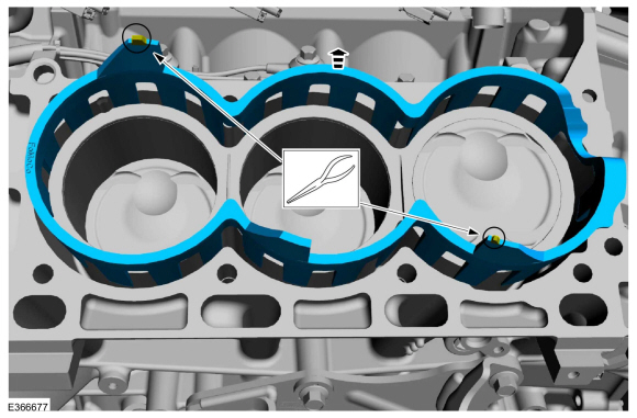
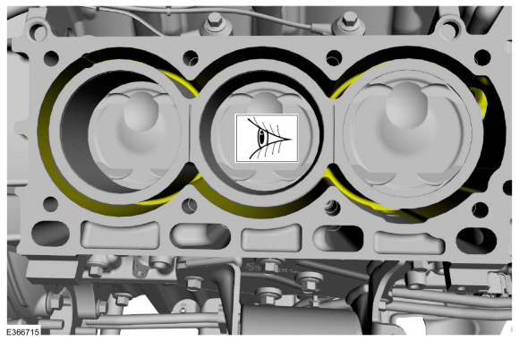
Inspect for any debri before installing the RH water jacket.
-
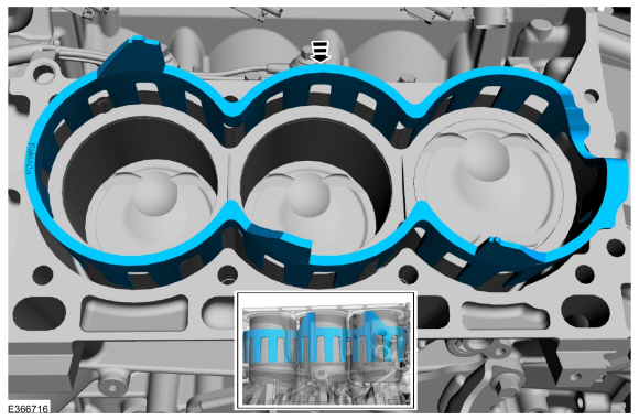
Install the RH water jacket flush with the bottom of the block.
-
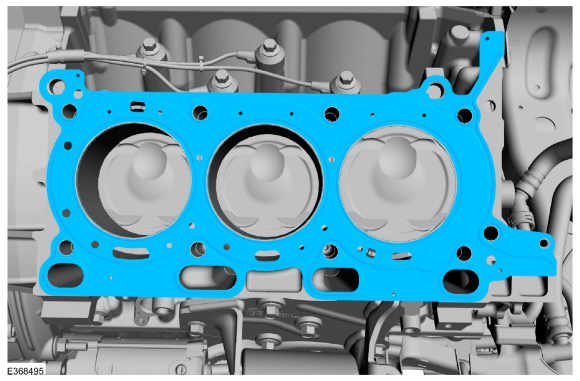
Install the RH cylinder head gasket.
-
NOTE:
Install new cylinder head bolts.
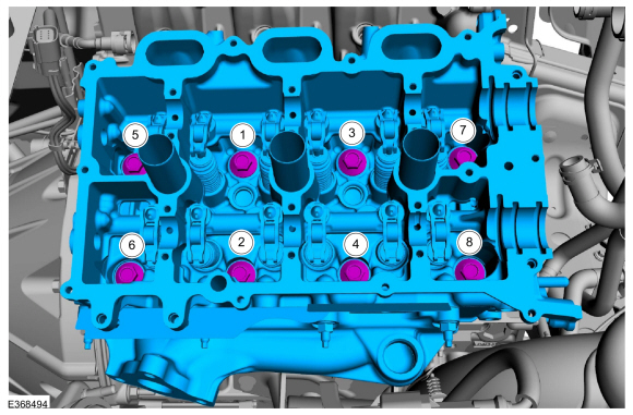
Install the RH cylinder head and the new bolts. Tighten in the sequence shown in 5 stages.
Torque:
Stage 1:
177 lb.in (20 Nm)
Stage 2:
33 lb.ft (45 Nm)
Stage 3:
90°
Stage 4:
90°
Stage 5:
90°
-
Install the RH M6 bolt.
Torque:
89 lb.in (10 Nm)
-
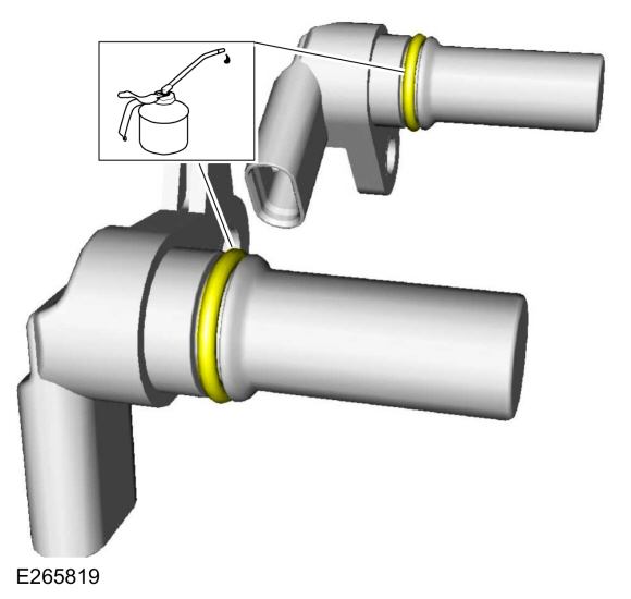
Lubricate the CMP sensor O-ring seal with clean engine oil.
Refer to: Specifications (303-01 Engine - 3.5L EcoBoost (272kW/370PS))
.
-
Install the bolts and the CMP sensors.
Torque:
71 lb.in (8 Nm)
-
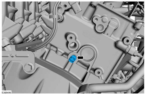
Install the new CHT sensor.
Torque:
97 lb.in (11 Nm)
-
-
Connect the pin-type retainers.
-
Connect the CHT sensor electrical connector.
-
Connect the CMP sensor electrical connectors.
-
Install the wiring harness ground and the studbolt. Position back the wire retainer.
Torque:
Stage 1:
89 lb.in (10 Nm)
Stage 2:
20°
-
Install the heat shield and the retainers.
Torque:
89 lb.in (10 Nm)
-
Install the fuel rail-to-fuel rail high-pressure fuel tube and tighten the flare nuts.
Torque:
Stage 1:
89 lb.in (10 Nm)
Stage 2:
30 °
-
Install the port injection fuel rail.
Refer to: Port Injection Fuel Rail (303-04A Fuel Charging and Controls -
3.5L EcoBoost (272kW/370PS), Removal and Installation).
-
Install the RH camshaft.
Refer to: Camshaft RH (303-01 Engine - 3.5L EcoBoost (272kW/370PS), Removal and Installation).
-
-
Install the cabin heater pump and bolts.
-
Connect the pin-type retainer.
-
Connect the electrical connector.
-
Install the EGR cooler.
Refer to: Exhaust Gas Recirculation (EGR) Cooler (303-08 Engine
Emission Control - 3.5L EcoBoost (272kW/370PS), Removal and
Installation).
-
Install the RH turbocharger.
Refer to: Turbocharger RH (303-04B Fuel Charging and Controls -
Turbocharger - 3.5L EcoBoost (272kW/370PS), Removal and Installation).
-
Connect the battery ground cable.
Refer to: Battery Cables (414-01 Battery, Mounting and Cables, Removal and Installation).
-
Road test the vehicle.
Special Tool(s) /
General Equipment
Long Nose Pliers
Materials
Name
Specification
Motorcraft® Silicone Gasket RemoverZC-30-A, AZC-30-C
-
Motorcraft® Metal Surface Prep WipesZC-31-B
-
Removal
NOTICE:
During engine repair procedures, cleanliness is extremely
important...
Special Tool(s) /
General Equipment
205-142
(T80T-4000-J)
Installer, Differential Bearing Cone
205-149
(T80T-4000-R)
Installer, Spindle Bearing
205-150
(T80T-4000-S)
Installer, Spindle Bearing
205-153
(T80T-4000-W)
Handle
303-1663Installer, VDOP Seal
307-399Alignment Pins, Transmission Fluid PumpTKIT-2002N-DEWTKIT-2..
Other information:
Inspection and Verification
Diagnostics in this manual assume a certain skill level and knowledge of Ford-specific diagnostic practices. REFER to: Diagnostic Methods (100-00 General Information, Description and Operation).
Verify the customer concern.
Visually inspect for obvious signs of mechanical or electrical damage.
If an obvious cause for an observed or..
Removal
NOTICE:
Suspension fasteners are critical parts that affect the
performance of vital components and systems. Failure of these fasteners
may result in major service expense. Use the same or equivalent parts if
replacement is necessary. Do not use a replacement part of lesser
quality or substitute design. Tighten fasteners as specified.
Measure the distance fr..


 Cylinder Head LH. Removal and Installation
 Engine Front Cover. Removal and Installation