Lincoln Navigator: Engine - 3.5L EcoBoost (272kW/370PS) / Engine Front Cover. Removal and Installation
Special Tool(s) /
General Equipment
 |
205-142
(T80T-4000-J)
Installer, Differential Bearing Cone |
 |
205-149
(T80T-4000-R)
Installer, Spindle Bearing |
 |
205-150
(T80T-4000-S)
Installer, Spindle Bearing |
 |
205-153
(T80T-4000-W)
Handle |
 |
303-1663
Installer, VDOP Seal |
 |
307-399
Alignment Pins, Transmission Fluid Pump
TKIT-2002N-DEW
TKIT-2000AP-FLM/LM |
| Oil Drain Equipment |
Materials
| Name |
Specification |
Motorcraft® High Performance Engine RTV Silicone
TA-357 |
WSE-M4G323-A6
|
Removal
NOTICE:
During engine repair procedures, cleanliness is extremely
important. Any foreign material, including any material created while
cleaning gasket surfaces that enters the oil passages, coolant passages
or the oil pan, may cause engine failure.
-
With the vehicle in NEUTRAL, position it on a hoist.
Refer to: Jacking and Lifting (100-02 Jacking and Lifting, Description and Operation).
-
Release the fuel system pressure.
Refer to: Fuel System Pressure Release (310-00 Fuel System - General
Information - 3.5L EcoBoost (272kW/370PS), General Procedures).
-
Remove the following items:
-
Remove the undershields.
Refer to: Engine Front Undershield (501-02 Front End Body Panels, Removal and Installation).
Refer to: Engine Rear Undershield (501-02 Front End Body Panels, Removal and Installation).
-
Remove the charge air cooler outlet pipe.
Refer to: Charge Air Cooler (CAC) Outlet Pipe (303-12 Intake Air
Distribution and Filtering - 3.5L EcoBoost (272kW/370PS), Removal and
Installation).
-
Remove the LH valve cover.
Refer to: Valve Cover LH (303-01 Engine - 3.5L EcoBoost (272kW/370PS), Removal and Installation).
-
Remove the RH valve cover.
Refer to: Valve Cover RH (303-01 Engine - 3.5L EcoBoost (272kW/370PS), Removal and Installation).
-
Remove the thermostat housing.
Refer to: Thermostat Housing (303-03 Engine Cooling - 3.5L EcoBoost (272kW/370PS), Removal and Installation).
-
Remove the coolant pump.
Refer to: Coolant Pump (303-03 Engine Cooling - 3.5L EcoBoost (272kW/370PS), Removal and Installation).
-
Remove the crankshaft front seal.
Refer to: Crankshaft Front Seal (303-01 Engine - 3.5L EcoBoost (272kW/370PS), Removal and Installation).
-
Remove the A/C compressor.
Refer to: Air Conditioning (A/C) Compressor (412-00 Climate Control System - General Information, Removal and Installation).
-
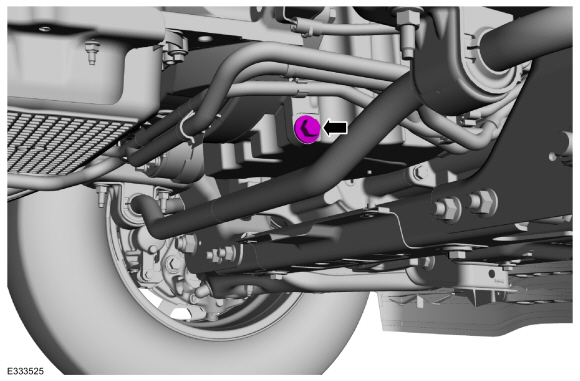
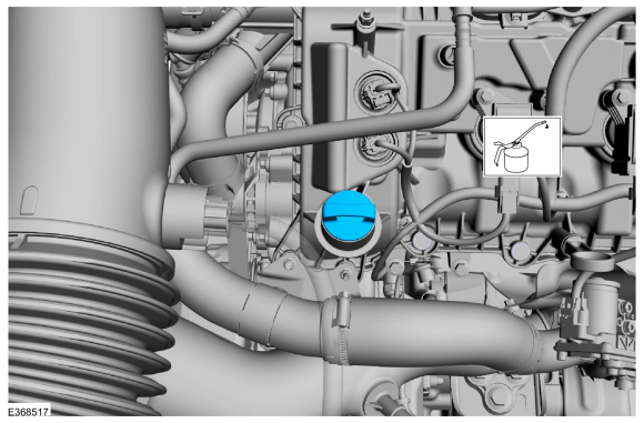
Remove the oil pan plug and drain the engine oil.
Use the General Equipment: Oil Drain Equipment
Torque:
20 lb.ft (27 Nm)
-
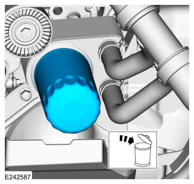
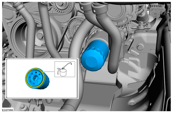
Remove and discard the engine oil filter.
Use the General Equipment: Oil Drain Equipment
-
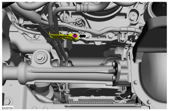
Remove the fasteners and position the wiring harness aside.
-
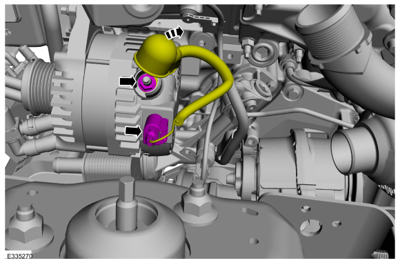
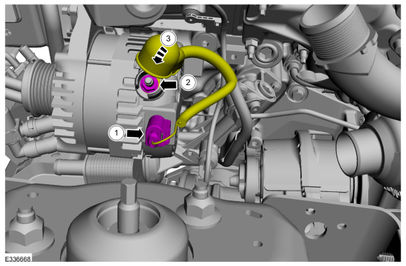
Disconnect the generator electrical connector, position
the B+ wire protective cover and remove the nut and the B+ wire.
-
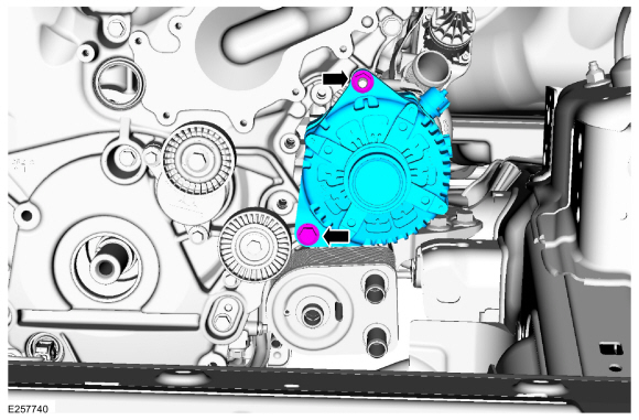
Remove the nut, bolt and the generator.
-
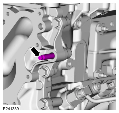
Remove the generator stud.
-
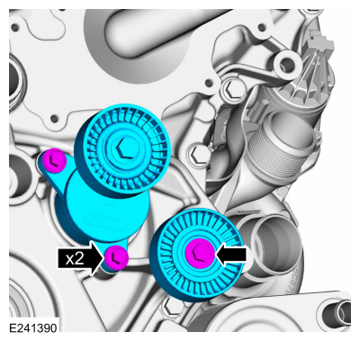
-
Remove the bolts and the accessory drive belt tensioner.
-
Remove the bolt and the accessory drive belt idler pulley.
-
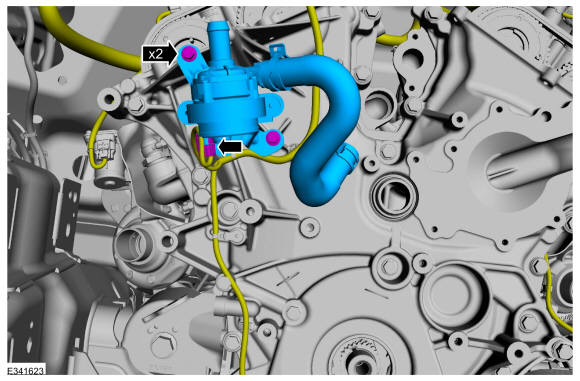
Disconnect the electrical connector, remove the bolts and position cabin heater coolant pump aside.
-
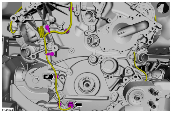
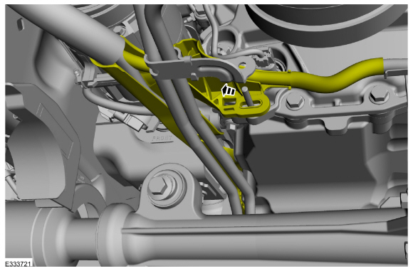
Disconnect the oil pump electrical connector, detach the pin-type retainers and position the wire harness aside.
-
Disconnect the generator wiring from the engine front cover.
-
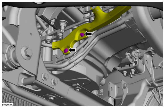
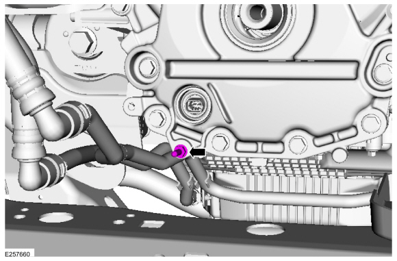
Remove the nut and position out the transmission cooler tube bracket.
-
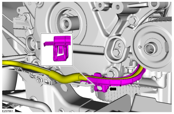
Position out the engine wiring harness.
-
Remove the transmission cooler bracket stud.
-
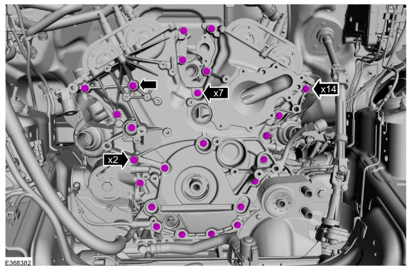
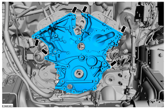
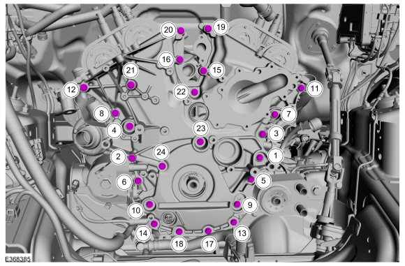
Remove the engine front cover bolts.
-
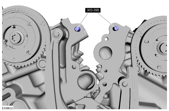
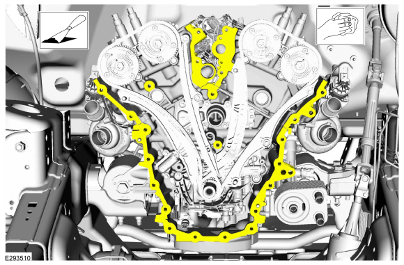
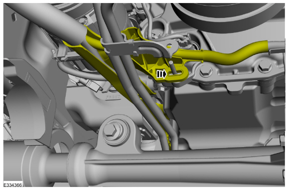
Using a pry tool on the pry pads shown, remove the engine front cover.
-
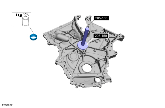
Using the special tools, remove the engine front cover to coolant pipe seal and discard.
Use Special Service Tool: 205-150
(T80T-4000-S)
Installer, Spindle Bearing.
, 205-153
(T80T-4000-W)
Handle.
-
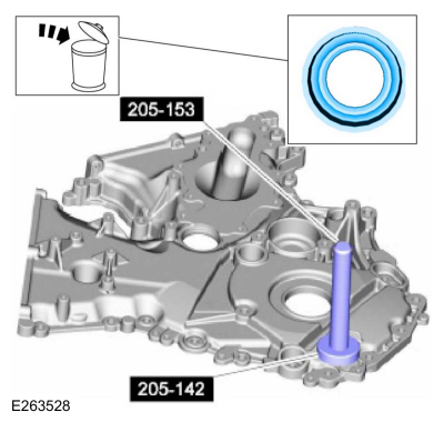
Using the special tools, remove and discard the oil pump electrical connector seal and discard.
Use Special Service Tool: 205-153
(T80T-4000-W)
Handle.
Install Special Service Tool: 205-142
(T80T-4000-J)
Installer, Differential Bearing Cone.
Installation
-
-
Clean and prepare the RTV sealing surface.
Refer to: RTV Sealing Surface Cleaning and Preparation (303-00 Engine System - General Information, General Procedures).
-
Clean and prepare the RTV sealing surface.
Refer to: RTV Sealing Surface Cleaning and Preparation (303-00 Engine System - General Information, General Procedures).
-
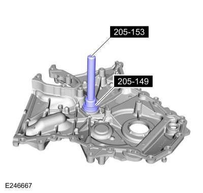
Using the special tools, install the new engine front cover to coolant pipe seal.
Use Special Service Tool: 205-149
(T80T-4000-R)
Installer, Spindle Bearing.
, 205-153
(T80T-4000-W)
Handle.
-
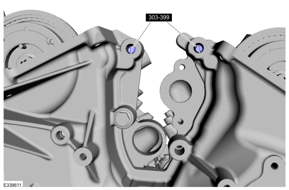
Install Special Service Tool: 307-399
Alignment Pins, Transmission Fluid Pump.
 |
|
-
-
NOTICE:
Failure to use Motorcraft® High Performance
Engine RTV Silicone may cause the engine oil to foam excessively and
result in serious engine damage.
NOTE:
The engine front cover and the 6 bolts must be
installed within 4 minutes of the initial sealant application. The
remainder of the engine front cover bolts must be installed and
tightened within 35 minutes of the initial sealant application. If the
time limits are exceeded, the sealant must be removed, the sealing area
cleaned and sealant reapplied. To clean the sealing area, use silicone
gasket remover and metal surface prep. Failure to follow this procedure
can cause future oil leakage.
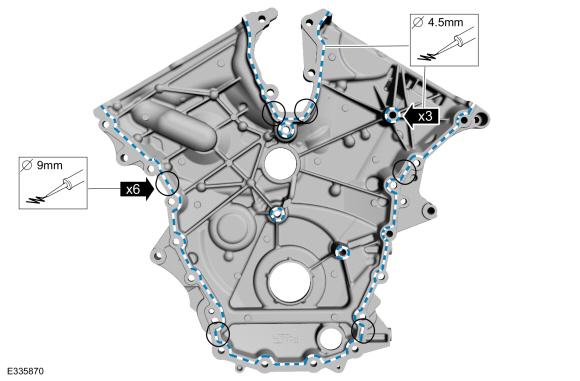
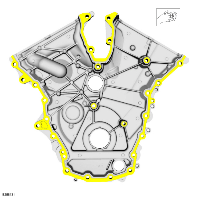
Apply a 4.5 mm (0.18 in) bead of Motorcraft® High
Performance Engine RTV Silicone to the engine front cover sealing
surfaces including the inner bolt bosses.
Material: Motorcraft® High Performance Engine RTV Silicone
/ TA-357
(WSE-M4G323-A6)
-
Apply a 9.0 mm (0.35 in) bead of Motorcraft® High
Performance Engine RTV Silicone to the oil pan-to-cylinder block joint
and the cylinder head-to-cylinder block joint areas of the engine front
cover in places as indicated.
Material: Motorcraft® High Performance Engine RTV Silicone
/ TA-357
(WSE-M4G323-A6)
 |
|
-
NOTE:
Make sure the 2 locating dowel pins are seated correctly in the cylinder block.
Install the engine front cover and the bolts.
Torque:
27 lb.in (3 Nm)
-
Remove Special Service Tool: 307-399
Alignment Pins, Transmission Fluid Pump.
-
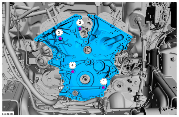
Install the engine front cover bolts. Tighten in the sequence shown in 2 stages.
Torque:
Stage 1:
Tighten bolts 1 thru 24 to:
177 lb.in (20 Nm)
Stage 2:
Tighten bolt 1 thru 24 an additional:
45°
-
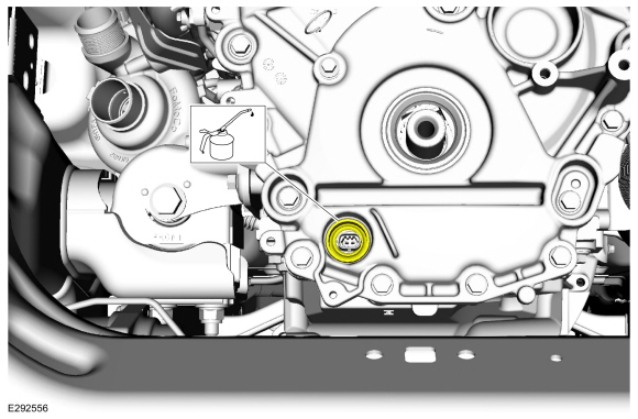
With clean oil, lubricate and position the new oil pump electrical connector seal.
Refer to: Specifications (303-01)
.
-
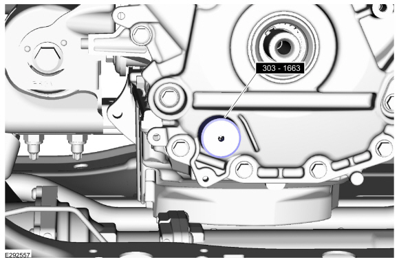
NOTICE:
If the oil pump electrical connector seal is not properly installed, it may result in oil leakage.
Using the special tool, install the oil pump electrical connector seal.
Install Special Service Tool: 303-1663
Installer, VDOP Seal.
-
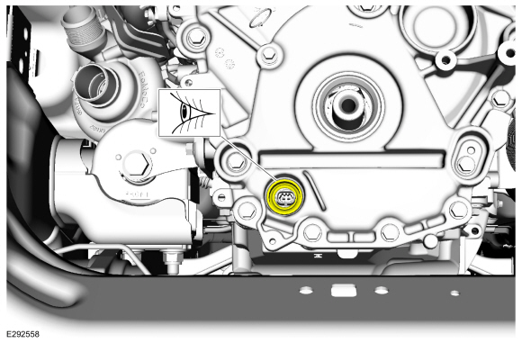
NOTE:
The front surface of the oil pump electrical
connector seal will be level with the engine front cover recess.
Inspect the oil pump electrical connector seal for proper installation.
-
Install the transmission cooler bracket stud.
-
Position back the engine wiring harness.
-
Position back the engine wiring harness. Position back the transmission cooler tube bracket and install the nut.
Torque:
106 lb.in (12 Nm)
-
Connect the generator wiring to the engine front cover.
-
Install the pin-type retainers and connect the oil pump electrical connector.
-
Install the cabin heater coolant pump and bolts. Connect the electrical connector.
Torque:
89 lb.in (10 Nm)
-
-
Install the accessory drive belt tensioner and bolts.
Torque:
18 lb.ft (25 Nm)
-
Install the accessory drive belt idler pulley and bolt.
Torque:
18 lb.ft (25 Nm)
-
Install the generator stud.
Torque:
71 lb.in (8 Nm)
-
Position back the generator. Install the nut and the bolt.
Torque:
35 lb.ft (48 Nm)
-
NOTICE:
When installing the B+ terminal nut to the
generator, finger-start the nut before tightening or component damage
may occur.
-
Connect the electrical connector.
-
Install the generator nut.
Torque:
150 lb.in (17 Nm)
-
Attach the starter motor wiring harness and retainer to the oil pan.
-
Install the following items:
-
Install the crankshaft front seal.
Refer to: Crankshaft Front Seal (303-01 Engine - 3.5L EcoBoost (272kW/370PS), Removal and Installation).
-
Install the coolant pump.
Refer to: Coolant Pump (303-03 Engine Cooling - 3.5L EcoBoost (272kW/370PS), Removal and Installation).
-
Install the thermostat housing.
Refer to: Thermostat Housing (303-03 Engine Cooling - 3.5L EcoBoost (272kW/370PS), Removal and Installation).
-
Install the RH valve cover.
Refer to: Valve Cover RH (303-01 Engine - 3.5L EcoBoost (272kW/370PS), Removal and Installation).
-
Install the LH valve cover.
Refer to: Valve Cover LH (303-01 Engine - 3.5L EcoBoost (272kW/370PS), Removal and Installation).
-
Install the charge air cooler outlet pipe.
Refer to: Air Cleaner Outlet Pipe (303-12 Intake Air Distribution and
Filtering - 3.5L EcoBoost (272kW/370PS), Removal and Installation).
-
Lubricate the oil filter seal with clean oil and install the new oil filter.
Refer to: Specifications (303-01)
.
Torque:
Stage 1:
44 lb.in (5 Nm)
Stage 2:
180°
-
Install the undershields.
Refer to: Engine Front Undershield (501-02 Front End Body Panels, Removal and Installation).
Refer to: Engine Rear Undershield (501-02 Front End Body Panels, Removal and Installation).
-
Fill the engine with clean engine oil.
Refer to: Specifications (303-01)
.
-
Pressurize the fuel system.
Refer to: Fuel System Pressure Release (310-00 Fuel System - General
Information - 3.5L EcoBoost (272kW/370PS), General Procedures).
-
After completing the repairs, perform the Misfire
Monitor Neutral Profile Correction procedure using a diagnostic scan
tool.
-
Road test the vehicle.
Special Tool(s) /
General Equipment
Long Nose Pliers
Materials
Name
Specification
Motorcraft® Silicone Gasket RemoverZC-30-A, AZC-30-C
-
Motorcraft® Metal Surface Prep WipesZC-31-B
-
Removal
NOTICE:
During engine repair procedures, cleanliness is extremely
important...
Special Tool(s) /
General Equipment
303-1246Engine Spreader BarTKIT-2006UF-FLMTKIT-2006UF-ROW
303-1654Lift Eyes
303-F070Support Bar, EngineTKIT-1999A-F/LTTKIT-1999A-FM/FLM
Vehicle/Axle Stands
Removal
NOTICE:
Use care when positioning the front axle housing or the
vacuum lines to the axle solenoid may become disconnected or damaged...
Other information:
Removal
NOTE:
Removal steps in this procedure may contain installation details.
Remove the pin-type retainers and position the air cleaner panel aside
Release the clips and position the RH and LH cowl filler panels aside...
Special Tool(s) /
General Equipment
6.5 mm Drill Bit
Self-Piercing Rivet (SPR) Remover/Installer
Belt Sander
Blind Rivet Gun
Locking Pliers
Materials
Name
Specification
Metal Bonding AdhesiveTA-1, TA-1-B, 3M™ 08115, LORD Fusor® 108B, Henkel Teroson EP 5055
-
Removal
NOTE:
The following procedure details re..
 Cylinder Head RH. Removal and Installation
 Engine Mount LH. Removal and Installation