Lincoln Navigator: Engine - 3.5L EcoBoost (272kW/370PS) / Cylinder Head LH. Removal and Installation
Special Tool(s) / General Equipment
| Long Nose Pliers |
Materials
| Name | Specification |
|---|---|
| Motorcraft® Silicone Gasket Remover ZC-30-A, AZC-30-C |
- |
| Motorcraft® Metal Surface Prep Wipes ZC-31-B |
- |
Removal
NOTICE: During engine repair procedures, cleanliness is extremely important. Any foreign material, including any material created while cleaning gasket surfaces that enters the oil passages, coolant passages or the oil pan, can cause engine failure.
-
With the vehicle in NEUTRAL, position it on a hoist.
Refer to: Jacking and Lifting (100-02 Jacking and Lifting, Description and Operation).
-
Release the fuel system pressure.
Refer to: Fuel System Pressure Release (310-00 Fuel System - General Information - 3.5L EcoBoost (272kW/370PS), General Procedures).
-
Disconnect the battery ground cable.
Refer to: Battery Cables (414-01 Battery, Mounting and Cables, Removal and Installation).
-
Remove the LH turbocharger.
Refer to: Turbocharger LH (303-04B Fuel Charging and Controls - Turbocharger - 3.5L EcoBoost (272kW/370PS), Removal and Installation).
-
Remove the LH camshaft.
Refer to: Camshaft LH (303-01 Engine - 3.5L EcoBoost (272kW/370PS), Removal and Installation).
-
Remove the port injection fuel rail.
Refer to: Port Injection Fuel Rail (303-04A Fuel Charging and Controls - 3.5L EcoBoost (272kW/370PS), Removal and Installation).
-
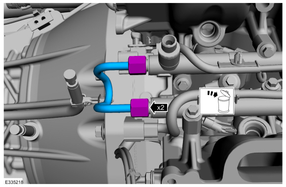
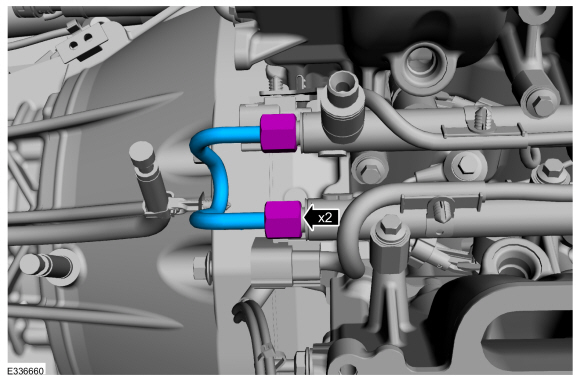
Remove and discard the fuel rail-to-fuel rail high-pressure tube.
 |
-
-
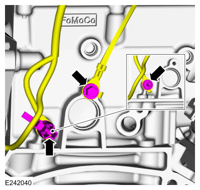
Position aside wire harness retainer. Remove the stud bolt and the ground wire.
-
Remove the bolt and position aside the body ground strap.
-
Position aside wire harness retainer. Remove the stud bolt and the ground wire.
 |
-
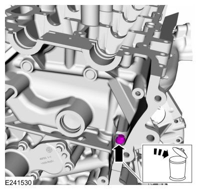
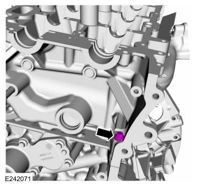
Remove and discard the LH M6 bolt.
 |
-
NOTICE: Place clean shop towels over exposed engine cavities. Carefully remove the towels so foreign material is not dropped into the engine. Any foreign material (including any material created while cleaning gasket surfaces) that enters the oil passages or the oil pan, may cause engine failure.
NOTICE: Aluminum surfaces are soft and can be scratched easily. Never place the cylinder head gasket surface, unprotected, on a bench surface
NOTE: The cylinder head bolts must be discarded and new bolts must be installed. They are tighten-to-yield designed and cannot be reused.
-
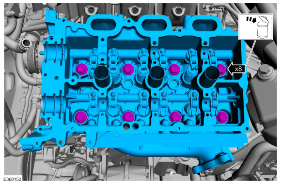
Remove and discard the bolts from the LH cylinder head.
-
Remove the cylinder head.
-
Remove and discard the bolts from the LH cylinder head.
 |
-
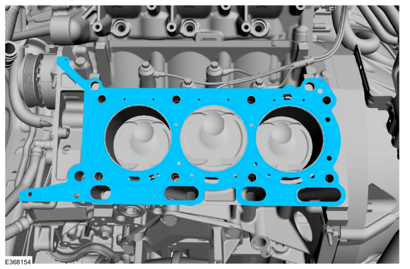
Remove and discard the LH cylinder head gasket.
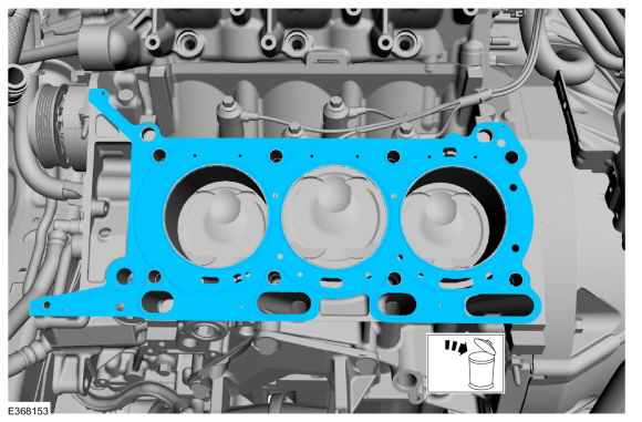 |
-
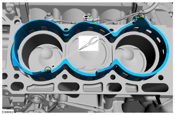
Remove the LH water jacket spacer.
Use the General Equipment: Long Nose Pliers
 |
-
NOTICE: Do not use metal scrapers, wire brushes, power abrasive discs or other abrasive means to clean the sealing surfaces. These tools cause scratches and gouges that make leak paths. Use a plastic scraping tool to remove all traces of the head gasket.
NOTE: Observe all warnings or cautions and follow all application directions contained on the packaging.
Make sure that the mating faces are clean and free of foreign material.
Material: Motorcraft® Silicone Gasket Remover / ZC-30-A, AZC-30-C
Material: Motorcraft® Metal Surface Prep Wipes / ZC-31-B
-
Support the cylinder head on a bench with the head
gasket side up. Check the cylinder head distortion and the cylinder
block distortion.
Refer to: Cylinder Head Distortion (303-00 Engine System - General Information, General Procedures).
Installation
-
Inspect for any debri before installing the LH water jacket.
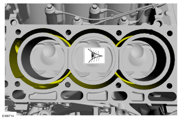 |
-
Install the LH water jacket flush with the bottom of the block.
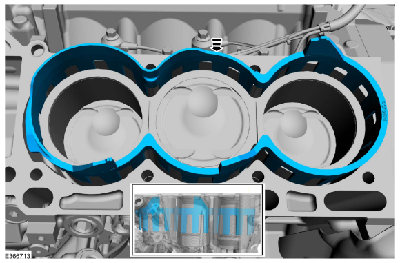 |
-
Install the LH cylinder head gasket.
 |
-
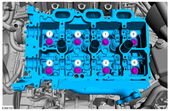
NOTE: Install new cylinder head bolts.
Install the LH cylinder head and the new bolts. Tighten in the sequence shown in 5 stages.
Torque:
Stage 1: 177 lb.in (20 Nm)
Stage 2: 33 lb.ft (45 Nm)
Stage 3: 90°
Stage 4: 90°
Stage 5: 90°
 |
-
Install the LH M6 bolt.
Torque: 89 lb.in (10 Nm)
 |
-
-
Install the ground strap & the stud bolt. Connect the wire retainer.
Torque:
Stage 1: 89 lb.in (10 Nm)
Stage 2: 20°
-
Position back the body ground strap and install the bolt.
Torque: 97 lb.in (11 Nm)
-
Install the ground strap & the stud bolt. Connect the wire retainer.
|
-
Position the flare nuts and connect the fuel rail-to-fuel rail high-pressure fuel tube.
Torque:
Stage 1: 89 lb.in (10 Nm)
Stage 2: 30°
 |
-
Install the port injection fuel rail.
Refer to: Port Injection Fuel Rail (303-04A Fuel Charging and Controls - 3.5L EcoBoost (272kW/370PS), Removal and Installation).
-
Install the LH camshaft.
Refer to: Camshaft LH (303-01 Engine - 3.5L EcoBoost (272kW/370PS), Removal and Installation).
-
Install the LH turbocharger.
Refer to: Turbocharger LH (303-04B Fuel Charging and Controls - Turbocharger - 3.5L EcoBoost (272kW/370PS), Removal and Installation).
-
Connect the battery ground cable.
Refer to: Battery Cables (414-01 Battery, Mounting and Cables, Removal and Installation).
-
Road test the vehicle.
 Crankshaft Rear Seal. Removal and Installation
Materials
Name
Specification
Motorcraft® High Performance Engine RTV SiliconeTA-357
WSE-M4G323-A6
Engine Oil - SAE 5W-30 - Synthetic Blend Motor OilXO-5W30-Q1SP
WSS-M2C946-B1
Removal
NOTICE:
During engine repair procedures, cleanliness is extremely
important...
 Cylinder Head RH. Removal and Installation
Special Tool(s) /
General Equipment
Long Nose Pliers
Materials
Name
Specification
Motorcraft® Silicone Gasket RemoverZC-30-A, AZC-30-C
-
Motorcraft® Metal Surface Prep WipesZC-31-B
-
Removal
NOTICE:
During engine repair procedures, cleanliness is extremely
important...
Other information:
Lincoln Navigator 2018-2026 Workshop Manual: Degas Bottle. Removal and Installation
Special Tool(s) / General Equipment Fluid Suction Gun Hose Clamp Remover/Installer Locking Pliers Materials Name Specification Motorcraft® Yellow Concentrated Antifreeze/CoolantVC-13-G WSS-M97B57-A1 Motorcraft® Orange Concentrated Antifreeze/CoolantVC-3-B WSS-M97B44-D Removal WARNING: Alway..
Lincoln Navigator 2018-2026 Workshop Manual: Rear Bumper Cover. Disassembly and Assembly
Special Tool(s) / General Equipment Electric Drill DISASSEMBLY NOTE: Disassembly steps in this procedure may contain assembly details. Remove the rear bumper cover. Refer to: Rear Bumper Cover (501-19 Bumpers, Removal and Installation). NOTE: The number and location of electrical connectors will vary depending on option content. ..
Categories
- Manuals Home
- 4th Gen Lincoln Navigator Service Manual (2018 - 2026)
- Brake Service Mode Activation and Deactivation. General Procedures
- Front Seat. Removal and Installation
- Telematics Control Unit (TCU) Module. Removal and Installation
- Body Control Module (BCM). Removal and Installation
- Vehicle Dynamics Control Module (VDM). Removal and Installation
Rear Drive Halfshafts. Diagnosis and Testing
Preliminary Inspection
Visually inspect the CV joints, housing, boots, and clamps for obvious signs of mechanical damage.If an obvious cause for an observed or reported concern is found, correct the cause (if possible) before proceeding to the next step
If the cause is not visually evident, verify the symptom and REFER to Symptom Chart: NVH.