Lincoln Navigator: Rear Suspension / Shock Absorber and Spring Assembly. Disassembly and Assembly
Special Tool(s) / General Equipment
| Spring Compressor | |
| Vise |
DISASSEMBLY
NOTICE: Suspension fasteners are critical parts that affect the performance of vital components and systems. Failure of these fasteners may result in major service expense. Use the same or equivalent parts if replacement is necessary. Do not use a replacement part of lesser quality or substitute design. Tighten fasteners as specified.
NOTE: Disassembly steps in this procedure may contain assembly details.
-
Remove the rear shock absorber and spring assembly.
Refer to: Shock Absorber and Spring Assembly (204-02 Rear Suspension, Removal and Installation).
-
 WARNING:
Coil springs and strut assemblies are compressed
under extreme load. Always use a spring compressor for disassembly.
Follow procedure instructions carefully and make sure the spring
compressor has the correct spring plates or adapters. Failure to follow
these instructions may result in serious personal injury.
WARNING:
Coil springs and strut assemblies are compressed
under extreme load. Always use a spring compressor for disassembly.
Follow procedure instructions carefully and make sure the spring
compressor has the correct spring plates or adapters. Failure to follow
these instructions may result in serious personal injury.
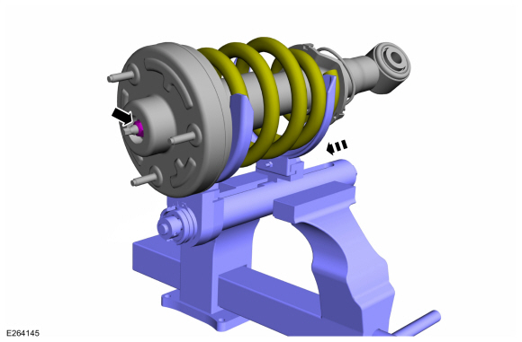
NOTICE: When installing a suitable spring compressor, use care not to damage the spring coating.
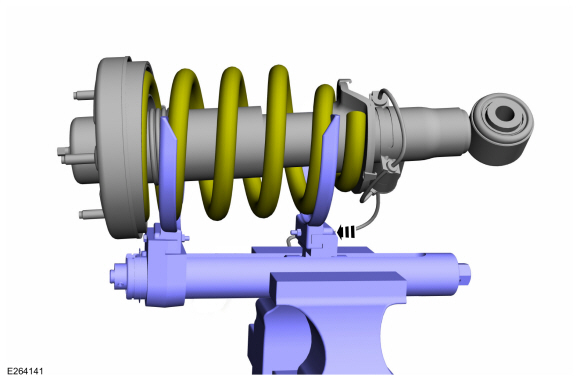
Compress the coil spring enough to relieve the tension on the shock absorber assembly.
Use the General Equipment: Spring Compressor
Use the General Equipment: Vise
 |
-
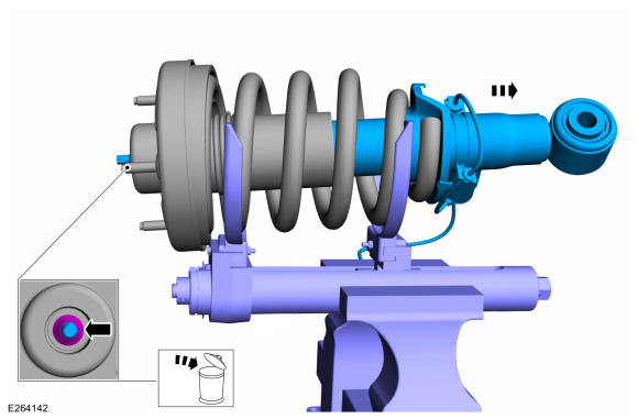
NOTICE: Do not use an impact wrench on the strut rod nut.
NOTE: Note the position of the components before disassembly.
NOTE: Use the hex-holding feature to prevent the strut rod from rotating while removing and installing the strut rod nut.
Carefully remove and discard the shock absorber rod nut and remove the rear shock absorber.
 |
-
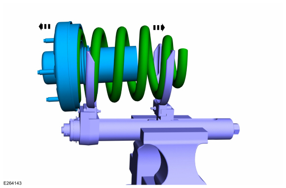
Remove the spring, dust boot and cap assembly.
 |
-
-
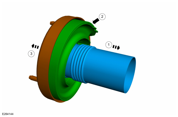
Remove the dust shield.
-
Remove the dust boot.
-
Remove the cap.
-
Remove the dust shield.
 |
ASSEMBLY
NOTE: If equipped with dynamic suspension, the RH and LH shock absorber assemblies are unique and cannot be used on opposite sides of the vehicle.
NOTE: Make sure that the components are installed to the position noted before removal.
-
To assemble, reverse the disassembly procedure.
-
NOTE: Utilize the hex holding feature to prevent the strut rod from turning while installing the strut rod nut.
Install and tighten the new strut rod nut.
Use the General Equipment: Vise
Use the General Equipment: Spring Compressor
Torque: 41 lb.ft (56 Nm)
 |
 Wheel Studs. Removal and Installation
Special Tool(s) /
General Equipment
211-023
(T74P-3044-A1)
C-Frame and Screw
Removal
NOTICE:
Suspension fasteners are critical parts that affect the
performance of vital components and systems...

Other information:
Lincoln Navigator 2018-2026 Workshop Manual: Third Row Seats - System Operation and Component Description. Description and Operation
System Operation System Diagram Item Description 1 MS-CAN 2 HS1-CAN 3 BCM 4 SCMJ 5 HS1-CAN 6 PCM 7 Liftgate Ajar Switch 8 Seat Control Switches 9 Power Folding Seat Motors 10 Hall-Effect Sensors 11 Motors 12 GWM Network Mess..
Lincoln Navigator 2018-2026 Workshop Manual: Lower Arm. Removal and Installation
Special Tool(s) / General Equipment 204-592/1Adapter for 204-592 Removal NOTICE: Suspension fasteners are critical parts that affect the performance of vital components and systems. Failure of these fasteners may result in major service expense. Use the same or equivalent parts if replacement is necessary. Do not use a replacement part of lesser quality or s..
Categories
- Manuals Home
- 4th Gen Lincoln Navigator Service Manual (2018 - 2026)
- Rear View Mirrors - System Operation and Component Description. Description and Operation
- Body Control Module (BCM). Removal and Installation
- Telematics Control Unit (TCU) Module. Removal and Installation
- Vehicle Dynamics Control Module (VDM). Removal and Installation
- Identification Codes. Description and Operation
Rear Drive Axle and Differential. Diagnosis and Testing
Symptom Chart(s)
Diagnostics in this manual assume a certain skill level and knowledge of Ford-specific diagnostic practices.
REFER to: Diagnostic Methods (100-00 General Information, Description and Operation).
Symptom Chart - Differential
Symptom Chart - Differential
Condition Actions Axle overheating GO to Pinpoint Test A Broken gear teeth on the ring gear or pinion GO to Pi