Lincoln Navigator: Second Row Seats / Second Row Seats. Diagnosis and Testing
DTC Chart: SCMC
Diagnostics in this manual assume a certain skill level and knowledge of Ford-specific diagnostic practices.
REFER to: Diagnostic Methods (100-00 General Information, Description and Operation).
SCMC DTC Chart
| DTC | Description | Action |
|---|---|---|
| B146F:00 | Back Bladder System Electropneumatic Failure: No Sub Type Information | GO to Pinpoint Test K |
| B146F:04 | Back Bladder System Electropneumatic Failure: System Internal Failure | GO to Pinpoint Test K |
| B146F:87 | Back Bladder System Electropneumatic Failure: Missing Message | GO to Pinpoint Test K |
| B1470:00 | Cushion Bladder System Electropneumatic Failure: No Sub Type Information | GO to Pinpoint Test K |
| B1470:04 | Cushion Bladder System Electropneumatic Failure: System Internal Failure | GO to Pinpoint Test K |
| B1470:87 | Cushion Bladder System Electropneumatic Failure: Missing Message | GO to Pinpoint Test K |
| B1473:11 | Pump Driver: Circuit Short To Ground | GO to Pinpoint Test K |
| U0140:00 | Lost Communication With Body Control Module: No Sub Type Information | GO to Pinpoint Test M |
| U0260:00 | Lost Communication With Seat Control Switch Module "A": No Sub Type Information | GO to Pinpoint Test O |
| U2100:00 | Initial Configuration Not Complete: No Sub Type Information | GO to Pinpoint Test Q |
| U3000:49 | Control Module: Internal Electronic Failure | GO to Pinpoint Test R |
DTC Chart: SCMD
Diagnostics in this manual assume a certain skill level and knowledge of Ford-specific diagnostic practices.
REFER to: Diagnostic Methods (100-00 General Information, Description and Operation).
SCMD DTC Chart
| DTC | Description | Action |
|---|---|---|
| B146F:00 | Back Bladder System Electropneumatic Failure: No Sub Type Information | GO to Pinpoint Test L |
| B146F:04 | Back Bladder System Electropneumatic Failure: System Internal Failure | GO to Pinpoint Test L |
| B146F:87 | Back Bladder System Electropneumatic Failure: Missing Message | GO to Pinpoint Test L |
| B1470:00 | Cushion Bladder System Electropneumatic Failure: No Sub Type Information | GO to Pinpoint Test L |
| B1470:04 | Cushion Bladder System Electropneumatic Failure: System Internal Failure | GO to Pinpoint Test L |
| B1470:87 | Cushion Bladder System Electropneumatic Failure: Missing Message | GO to Pinpoint Test L |
| B1473:11 | Pump Driver: Circuit Short To Ground | GO to Pinpoint Test L |
| U0140:00 | Lost Communication With Body Control Module: No Sub Type Information | GO to Pinpoint Test M |
| U0210:00 | Lost Communication With "Seat Control Module C": No Sub Type Information | GO to Pinpoint Test N |
| U0261:00 | Lost Communication With Seat Control Switch Module "B": No Sub Type Information | GO to Pinpoint Test P |
| U2100:00 | Initial Configuration Not Complete: No Sub Type Information | GO to Pinpoint Test Q |
| U3000:49 | Control Module: Internal Electronic Failure | GO to Pinpoint Test R |
DTC Chart: SCME
Diagnostics in this manual assume a certain skill level and knowledge of Ford-specific diagnostic practices.
REFER to: Diagnostic Methods (100-00 General Information, Description and Operation).
SCME DTC Chart
| DTC | Description | Action |
|---|---|---|
| B1031:11 | Left Rear Seat Heater: Circuit Short To Ground | GO to Pinpoint Test A |
| B1031:12 | Left Rear Seat Heater: Circuit Short To Battery | GO to Pinpoint Test A |
| B1031:13 | Left Rear Seat Heater: Circuit Open | GO to Pinpoint Test A |
| B1035:4B | Left Rear Seat Heater Element: Over Temperature | GO to Pinpoint Test A |
| B1039:11 | Left Rear Seat Heater Sensor: Circuit Short To Ground | GO to Pinpoint Test A |
| B1039:15 | Left Rear Seat Heater Sensor: Circuit Short To Battery or Open | GO to Pinpoint Test A |
| B1039:2A | Left Rear Seat Heater Sensor: Signal Stuck In Range | GO to Pinpoint Test A |
| B122C:11 | Left Seat Cushion Blower Speed Sensor: Circuit Short To Ground | GO to Pinpoint Test C |
| B122C:12 | Left Seat Cushion Blower Speed Sensor: Circuit Short To Battery | GO to Pinpoint Test C |
| B122D:11 | Left Seat Back Blower Speed Sensor: Circuit Short To Ground | GO to Pinpoint Test C |
| B122D:12 | Left Seat Back Blower Speed Sensor: Circuit Short To Battery | GO to Pinpoint Test C |
| B1648:11 | Left Rear Seat Blower: Circuit Short To Ground | GO to Pinpoint Test C |
| B1648:13 | Left Rear Seat Blower: Circuit Open | GO to Pinpoint Test C |
| All other Diagnostic Trouble Codes (DTCs) | - |
REFER to: Front Seats (501-10A Front Seats, Diagnosis and Testing). |
DTC Chart: SCMF
Diagnostics in this manual assume a certain skill level and knowledge of Ford-specific diagnostic practices.
REFER to: Diagnostic Methods (100-00 General Information, Description and Operation).
SCMF DTC Chart
| DTC | Description | Action |
|---|---|---|
| B1033:11 | Right Rear Seat Heater: Circuit Short To Ground | GO to Pinpoint Test B |
| B1033:12 | Right Rear Seat Heater: Circuit Short To Battery | GO to Pinpoint Test B |
| B1033:13 | Right Rear Seat Heater: Circuit Open | GO to Pinpoint Test B |
| B1037:4B | Right Rear Seat Heater Element: Over Temperature | GO to Pinpoint Test B |
| B103B:11 | Right Rear Seat Heater Sensor: Circuit Short To Ground | GO to Pinpoint Test B |
| B103B:15 | Right Rear Seat Heater Sensor: Circuit Short To Battery or Open | GO to Pinpoint Test B |
| B103B:2A | Right Rear Seat Heater Sensor: Signal Stuck In Range | GO to Pinpoint Test B |
| B122A:11 | Right Seat Cushion Blower Speed Sensor: Circuit Short To Ground | GO to Pinpoint Test D |
| B122A:12 | Right Seat Cushion Blower Speed Sensor: Circuit Short To Battery | GO to Pinpoint Test D |
| B122B:11 | Right Seat Back Blower Speed Sensor: Circuit Short To Ground | GO to Pinpoint Test D |
| B122B:12 | Right Seat Back Blower Speed Sensor: Circuit Short To Battery | GO to Pinpoint Test D |
| B1647:11 | Right Rear Seat Blower: Circuit Short To Ground | GO to Pinpoint Test D |
| B1647:13 | Right Rear Seat Blower: Circuit Open | GO to Pinpoint Test D |
| All other Diagnostic Trouble Codes (DTCs) | - |
REFER to: Front Seats (501-10A Front Seats, Diagnosis and Testing). |
DTC Chart: SCMJ
Diagnostics in this manual assume a certain skill level and knowledge of Ford-specific diagnostic practices.
REFER to: Diagnostic Methods (100-00 General Information, Description and Operation).
SCMJ DTC Chart
| DTC | Description | Action |
|---|---|---|
| B137A:11 | Left Entry Output: Circuit Short To Ground | GO to Pinpoint Test I |
| B137A:15 | Left Entry Output: Circuit Short To Battery or Open | GO to Pinpoint Test I |
| B137B:11 | Right Entry Output: Circuit Short To Ground | GO to Pinpoint Test J |
| B137B:15 | Right Entry Output: Circuit Short To Battery or Open | GO to Pinpoint Test J |
| B1546:23 | Left Entry Switch: Signal Stuck Low | GO to Pinpoint Test I |
| B1547:23 | Right Entry Switch: Signal Stuck Low | GO to Pinpoint Test J |
| B1549:11 | Second Row Center Fold Output: Circuit Short To Ground | GO to Pinpoint Test G |
| B1549:15 | Second Row Center Fold Output: Circuit Short To Battery or Open | GO to Pinpoint Test G |
| B154A:11 | Second Row Left Fold Output: Circuit Short To Ground | GO to Pinpoint Test F |
| B154A:15 | Second Row Left Fold Output: Circuit Short To Battery or Open | GO to Pinpoint Test F |
| B1550:11 | Second Row Right Fold Output: Circuit Short To Ground | GO to Pinpoint Test H |
| B1550:15 | Second Row Right Fold Output: Circuit Short To Battery or Open | GO to Pinpoint Test H |
| B1553:11 | Second Row Seat Fold Switch: Circuit Short To Ground | GO to Pinpoint Test E |
| B1553:13 | Second Row Seat Fold Switch: Circuit Open | GO to Pinpoint Test E |
| B1553:2A | Second Row Seat Fold Switch: Signal Stuck In Range | GO to Pinpoint Test E |
| All other Diagnostic Trouble Codes (DTCs) | - |
REFER to: Third Row Seats (501-10C Third Row Seats, Diagnosis and Testing). |
Symptom Chart(s)
Symptom Chart: Second Row Seats
Diagnostics in this manual assume a certain skill level and knowledge of Ford-specific diagnostic practices.
REFER to: Diagnostic Methods (100-00 General Information, Description and Operation).
Symptom Chart
| Condition | Possible Sources | Actions |
|---|---|---|
|
|
|
|
|
|
|
|
|
|
|
|
|
|
|
|
|
|
|
|
|
|
|
|
|
|
|
|
|
|
|
|
|
|
|
|
|
|
|
|
|
|
|
|
|
|
|
|
Pinpoint Tests
|
Refer to Wiring Diagrams Cell 119 for schematic and connector information. Normal Operation and Fault Conditions
REFER to: Second Row Seats - System Operation and Component Description (501-10B Second Row Seats, Description and Operation). DTC Fault Trigger Conditions
Possible Sources
Visual Inspection and Pre-checks
|
||||||||||||||||||||||||
| A1 CHECK FOR RACM (REAR AUDIO CONTROL MODULE) DIAGNOSTIC TROUBLE CODES (DTCS) | ||||||||||||||||||||||||
Are any RACM Diagnostic Trouble Codes (DTCs) present?
|
||||||||||||||||||||||||
| A2 CHECK FOR SCME (FRONT SEAT CLIMATE CONTROL MODULE) DIAGNOSTIC TROUBLE CODES (DTCS) | ||||||||||||||||||||||||
Are any SCME Diagnostic Trouble Codes (DTCs) present?
|
||||||||||||||||||||||||
| A3 CHECK THE HEATED SEAT VOLTAGE SUPPLY CIRCUITS FOR AN OPEN | ||||||||||||||||||||||||
Are the voltages greater than 11 volts?
|
||||||||||||||||||||||||
| A4 CHECK THE HEATED SEAT GROUND CIRCUITS FOR AN OPEN | ||||||||||||||||||||||||
Are the resistances less than 3 ohms?
|
||||||||||||||||||||||||
| A5 CHECK THE HEATER ELEMENT POWER CIRCUIT FOR A SHORT TO VOLTAGE | ||||||||||||||||||||||||
Is any voltage present?
|
||||||||||||||||||||||||
| A6 CHECK THE HEATER ELEMENT POWER CIRCUIT FOR AN OPEN OR SHORT TO GROUND | ||||||||||||||||||||||||
Are the resistances greater than 10,000 ohms between the left rear seat cushion heater mat and ground; and less than 3 ohms between the left rear seat cushion heater mat and the DSM ?
|
||||||||||||||||||||||||
| A7 CHECK THE HEATED SEAT TEMPERATURE SENSOR CIRCUIT FOR A SHORT TO VOLTAGE | ||||||||||||||||||||||||
Is any voltage present?
|
||||||||||||||||||||||||
| A8 CHECK THE HEATED SEAT TEMPERATURE SENSOR CIRCUIT FOR AN OPEN OR SHORT TO GROUND | ||||||||||||||||||||||||
Is the resistance greater than 10,000 ohms between the left rear seat cushion heater mat and ground; and less than 3 ohms between the left rear seat cushion heater mat and the DSM ?
|
||||||||||||||||||||||||
| A9 CHECK THE HEATED SEAT TEMPERATURE SENSOR RETURN CIRCUIT FOR AN OPEN OR SHORT TO GROUND | ||||||||||||||||||||||||
Is the resistance greater than 10,000 ohms between the left rear seat cushion heater mat and ground; and less than 3 ohms between the left rear seat cushion heater mat and the DSM ?
|
||||||||||||||||||||||||
| A10 CHECK THE HEATER ELEMENT GROUND CIRCUIT FOR AN OPEN | ||||||||||||||||||||||||
Are the resistances less than 3 ohms?
|
||||||||||||||||||||||||
| A11 CHECK THE CUSHION HEATED SEAT MAT FOR AN OPEN OR SHORT TO GROUND | ||||||||||||||||||||||||
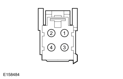
Is the resistance between 0.6 and 2 ohms between pins 1 and 4; and greater than 10,000 ohms between pin 1 and ground?
|
||||||||||||||||||||||||
| A12 CHECK THE BACKREST HEATED SEAT MAT FOR AN OPEN OR SHORT TO GROUND | ||||||||||||||||||||||||
Is the resistance between 0.6 and 2 ohms between pins 1 and 2; and greater than 10,000 ohms between pin 2 and ground?
|
||||||||||||||||||||||||
| A13 CHECK THE CIRCUIT BETWEEN THE CUSHION HEATER MAT AND BACKREST HEATER MAT FOR AN OPEN AND SHORT TO GROUND | ||||||||||||||||||||||||
Is the resistance greater than 10,000 ohms between the left rear seat cushion heater mat and ground; and less than 3 ohms between the left rear seat cushion heater mat and the backrest heater mat?
|
||||||||||||||||||||||||
| A14 CHECK THE HEATED SEAT TEMPERATURE SENSOR FOR AN OPEN OR SHORT TO GROUND | ||||||||||||||||||||||||
Is the resistance between 300 and 300,000 ohms between pins 2 and 3; and greater than 10,000 ohms between pin 2 and ground?
|
||||||||||||||||||||||||
| A15 CHECK THE DSM (DRIVER FRONT SEAT MODULE) OPERATION | ||||||||||||||||||||||||
Is the concern still present?
|
||||||||||||||||||||||||
| A16 VERIFY THE SRS (SUPPLEMENTAL RESTRAINT SYSTEM) PROVES OUT SUCCESSFULLY | ||||||||||||||||||||||||
Did the SRS prove out successfully?
|
 WARNING:
Incorrect repair techniques or actions can cause an
accidental Supplemental Restraint System (SRS) deployment. Never
compromise or depart from these instructions. Failure to precisely
follow all instructions could result in serious personal injury from an
accidental deployment.
WARNING:
Incorrect repair techniques or actions can cause an
accidental Supplemental Restraint System (SRS) deployment. Never
compromise or depart from these instructions. Failure to precisely
follow all instructions could result in serious personal injury from an
accidental deployment.


 C3361-1, Component Side
 C3360-1, Component Side
|
Refer to Wiring Diagrams Cell 119 for schematic and connector information. Normal Operation and Fault Conditions
REFER to: Second Row Seats - System Operation and Component Description (501-10B Second Row Seats, Description and Operation). DTC Fault Trigger Conditions
Possible Sources
Visual Inspection and Pre-checks
NOTE: The SRS must be fully operational and free of faults before releasing the vehicle to the customer. |
||||||||||||||||||||||||
| B1 CHECK FOR RACM (REAR AUDIO CONTROL MODULE) DIAGNOSTIC TROUBLE CODES (DTCS) | ||||||||||||||||||||||||
Are any RACM Diagnostic Trouble Codes (DTCs) present?
|
||||||||||||||||||||||||
| B2 CHECK FOR SCMF (REAR SEAT CLIMATE CONTROL MODULE) DIAGNOSTIC TROUBLE CODES (DTCS) | ||||||||||||||||||||||||
Are any SCMF Diagnostic Trouble Codes (DTCs) present?
|
||||||||||||||||||||||||
| B3 CHECK THE HEATED SEAT VOLTAGE SUPPLY CIRCUITS FOR AN OPEN | ||||||||||||||||||||||||
Are the voltages greater than 11 volts?
|
||||||||||||||||||||||||
| B4 CHECK THE HEATED SEAT GROUND CIRCUITS FOR AN OPEN | ||||||||||||||||||||||||
Are the resistances less than 3 ohms?
|
||||||||||||||||||||||||
| B5 CHECK THE HEATER ELEMENT POWER CIRCUIT FOR A SHORT TO VOLTAGE | ||||||||||||||||||||||||
Is any voltage present?
|
||||||||||||||||||||||||
| B6 CHECK THE HEATER ELEMENT POWER CIRCUIT FOR AN OPEN OR SHORT TO GROUND | ||||||||||||||||||||||||
Are the resistances greater than 10,000 ohms between the left rear seat cushion heater mat and ground; and less than 3 ohms between the left rear seat cushion heater mat and the SCMB ?
|
||||||||||||||||||||||||
| B7 CHECK THE HEATED SEAT TEMPERATURE SENSOR CIRCUIT FOR A SHORT TO VOLTAGE | ||||||||||||||||||||||||
Is any voltage present?
|
||||||||||||||||||||||||
| B8 CHECK THE HEATED SEAT TEMPERATURE SENSOR CIRCUIT FOR AN OPEN OR SHORT TO GROUND | ||||||||||||||||||||||||
Is the resistance greater than 10,000 ohms between the left rear seat cushion heater mat and ground; and less than 3 ohms between the left rear seat cushion heater mat and the SCMB ?
|
||||||||||||||||||||||||
| B9 CHECK THE HEATED SEAT TEMPERATURE SENSOR RETURN CIRCUIT FOR AN OPEN OR SHORT TO GROUND | ||||||||||||||||||||||||
Is the resistance greater than 10,000 ohms between the left rear seat cushion heater mat and ground; and less than 3 ohms between the left rear seat cushion heater mat and the SCMB ?
|
||||||||||||||||||||||||
| B10 CHECK THE HEATER ELEMENT GROUND CIRCUIT FOR AN OPEN | ||||||||||||||||||||||||
Are the resistances less than 3 ohms?
|
||||||||||||||||||||||||
| B11 CHECK THE CUSHION HEATED SEAT MAT FOR AN OPEN OR SHORT TO GROUND | ||||||||||||||||||||||||
Is the resistance between 0.6 and 2 ohms between pins 1 and 4; and greater than 10,000 ohms between pin 1 and ground?
|
||||||||||||||||||||||||
| B12 CHECK THE BACKREST HEATED SEAT MAT FOR AN OPEN OR SHORT TO GROUND | ||||||||||||||||||||||||
Is the resistance between 0.6 and 2 ohms between pins 1 and 2; and greater than 10,000 ohms between pin 2 and ground?
|
||||||||||||||||||||||||
| B13 CHECK THE CIRCUIT BETWEEN THE CUSHION HEATER MAT AND BACKREST HEATER MAT FOR AN OPEN AND SHORT TO GROUND | ||||||||||||||||||||||||
Is the resistance greater than 10,000 ohms between the right rear seat cushion heater mat and ground; and less than 3 ohms between the right rear seat cushion heater mat and the backrest heater mat?
|
||||||||||||||||||||||||
| B14 CHECK THE HEATED SEAT TEMPERATURE SENSOR FOR AN OPEN OR SHORT TO GROUND | ||||||||||||||||||||||||
Is the resistance between 300 and 300,000 ohms between pins 2 and 3; and greater than 10,000 ohms between pin 2 and ground?
|
||||||||||||||||||||||||
| B15 CHECK THE SCMB (PASSENGER FRONT SEAT MODULE) OPERATION | ||||||||||||||||||||||||
Is the concern still present?
|
||||||||||||||||||||||||
| B16 VERIFY THE SRS (SUPPLEMENTAL RESTRAINT SYSTEM) PROVES OUT SUCCESSFULLY | ||||||||||||||||||||||||
Did the SRS prove out successfully?
|
|
Refer to Wiring Diagrams Cell 119 for schematic and connector information. Normal Operation and Fault Conditions
REFER to: Second Row Seats - System Operation and Component Description (501-10B Second Row Seats, Description and Operation). DTC Fault Trigger Conditions
Possible Sources
|
||||||||||||||||||||||||||||||||||
| C1 CHECK THE LEFT REAR HEATED SEAT OPERATION | ||||||||||||||||||||||||||||||||||
Does the left rear heated seat operate correctly?
|
||||||||||||||||||||||||||||||||||
| C2 CHECK FOR RACM (REAR AUDIO CONTROL MODULE) DIAGNOSTIC TROUBLE CODES (DTCS) | ||||||||||||||||||||||||||||||||||
Are any RACM Diagnostic Trouble Codes (DTCs) present?
|
||||||||||||||||||||||||||||||||||
| C3 CHECK THE BLOWER MOTOR AND DSM (DRIVER FRONT SEAT MODULE) CONNECTIONS | ||||||||||||||||||||||||||||||||||
Is the concern still present?
|
||||||||||||||||||||||||||||||||||
| C4 CHECK THE BLOWER MOTOR CIRCUITS FOR A SHORT TO VOLTAGE | ||||||||||||||||||||||||||||||||||
Is any voltage present?
|
||||||||||||||||||||||||||||||||||
| C5 CHECK THE BLOWER MOTOR CIRCUITS FOR A SHORT TO GROUND | ||||||||||||||||||||||||||||||||||
Are the resistances greater than 10,000 ohms?
|
||||||||||||||||||||||||||||||||||
| C6 CHECK THE BLOWER MOTOR CIRCUITS FOR AN OPEN | ||||||||||||||||||||||||||||||||||
Are the resistances less than 3 ohms?
|
||||||||||||||||||||||||||||||||||
| C7 CHECK THE BLOWER MOTOR OPERATION | ||||||||||||||||||||||||||||||||||
Is the concern still present?
|
||||||||||||||||||||||||||||||||||
| C8 CHECK THE DSM (DRIVER FRONT SEAT MODULE) OPERATION | ||||||||||||||||||||||||||||||||||
Is the concern still present?
|
||||||||||||||||||||||||||||||||||
| C9 VERIFY THE SRS (SUPPLEMENTAL RESTRAINT SYSTEM) PROVES OUT SUCCESSFULLY | ||||||||||||||||||||||||||||||||||
Did the SRS prove out successfully?
|
|
Refer to Wiring Diagrams Cell 119 for schematic and connector information. Normal Operation and Fault Conditions
REFER to: Second Row Seats - System Operation and Component Description (501-10B Second Row Seats, Description and Operation). DTC Fault Trigger Conditions
Possible Sources
|
||||||||||||||||||||||||||||||||||
| D1 CHECK THE LEFT REAR HEATED SEAT OPERATION | ||||||||||||||||||||||||||||||||||
Does the right rear heated seat operate correctly?
|
||||||||||||||||||||||||||||||||||
| D2 CHECK FOR RACM (REAR AUDIO CONTROL MODULE) DIAGNOSTIC TROUBLE CODES (DTCS) | ||||||||||||||||||||||||||||||||||
Are any RACM Diagnostic Trouble Codes (DTCs) present?
|
||||||||||||||||||||||||||||||||||
| D3 CHECK THE BLOWER MOTOR AND SCMB (PASSENGER FRONT SEAT MODULE) CONNECTIONS | ||||||||||||||||||||||||||||||||||
Is the concern still present?
|
||||||||||||||||||||||||||||||||||
| D4 CHECK THE BLOWER MOTOR CIRCUITS FOR A SHORT TO VOLTAGE | ||||||||||||||||||||||||||||||||||
Is any voltage present?
|
||||||||||||||||||||||||||||||||||
| D5 CHECK THE BLOWER MOTOR CIRCUITS FOR A SHORT TO GROUND | ||||||||||||||||||||||||||||||||||
Are the resistances greater than 10,000 ohms?
|
||||||||||||||||||||||||||||||||||
| D6 CHECK THE BLOWER MOTOR CIRCUITS FOR AN OPEN | ||||||||||||||||||||||||||||||||||
Are the resistances less than 3 ohms?
|
||||||||||||||||||||||||||||||||||
| D7 CHECK THE BLOWER MOTOR OPERATION | ||||||||||||||||||||||||||||||||||
Is the concern still present?
|
||||||||||||||||||||||||||||||||||
| D8 CHECK THE SCMB (PASSENGER FRONT SEAT MODULE) OPERATION | ||||||||||||||||||||||||||||||||||
Is the concern still present?
|
||||||||||||||||||||||||||||||||||
| D9 VERIFY THE SRS (SUPPLEMENTAL RESTRAINT SYSTEM) PROVES OUT SUCCESSFULLY | ||||||||||||||||||||||||||||||||||
Did the SRS prove out successfully?
|
|
Refer to Wiring Diagrams Cell 120 for schematic and connector information. Normal Operation and Fault Conditions
REFER to: Second Row Seats - System Operation and Component Description (501-10B Second Row Seats, Description and Operation). DTC Fault Trigger Conditions
Possible Sources
NOTE: Make sure the second row power release seats manually release and latch before troubleshooting the electrical system. |
||||||||||||||||||||
| E1 CHECK THE SCMJ (POWER FOLD SEAT MODULE) DIAGNOSTIC TROUBLE CODES (DTCS) | ||||||||||||||||||||
Were any Diagnostic Trouble Codes (DTCs) retrieved?
|
||||||||||||||||||||
| E2 CHECK THE SCMJ (POWER FOLD SEAT MODULE) DIAGNOSTIC TROUBLE CODES (DTCS) WITH THE SECOND ROW SEAT CONTROL SWITCH DISCONNECTED | ||||||||||||||||||||
Was DTC B1553:13 retrieved?
|
||||||||||||||||||||
| E3 CHECK THE SECOND ROW SEAT CONTROL SWITCH CIRCUIT FOR A SHORT TO GROUND | ||||||||||||||||||||
Is the resistance greater than 10,000 ohms?
|
||||||||||||||||||||
| E4 CHECK THE SCMJ (POWER FOLD SEAT MODULE) DIAGNOSTIC TROUBLE CODES (DTCS) WITH A FUSED JUMPER WIRE INSTALLED IN THE SECOND ROW SEAT CONTROL SWITCH | ||||||||||||||||||||
Was DTC B1553:11 retrieved?
|
||||||||||||||||||||
| E5 CHECK THE SECOND ROW SEAT CONTROL SWITCH CIRCUITS FOR AN OPEN | ||||||||||||||||||||
Are the resistances less than 3 ohms?
|
||||||||||||||||||||
| E6 CHECK THE SECOND ROW SEAT CONTROL SWITCH RESISTANCE VALUES | ||||||||||||||||||||
Is the resistance within the specified range for each control switch position?
|
||||||||||||||||||||
| E7 CHECK THE SECOND ROW SEAT CONTROL SWITCH CIRCUITS FOR EXCESSIVE RESISTANCE | ||||||||||||||||||||
Are the resistances less than 3 ohms?
|
||||||||||||||||||||
| E8 CHECK THE SCMJ (POWER FOLD SEAT MODULE) OPERATION | ||||||||||||||||||||
Is the concern still present?
|

|
Refer to Wiring Diagrams Cell 120 for schematic and connector information. Normal Operation and Fault Conditions
REFER to: Second Row Seats - System Operation and Component Description (501-10B Second Row Seats, Description and Operation). DTC Fault Trigger Conditions
Possible Sources
Visual Inspection and Pre-checks
|
||||||||||||||||||||
| F1 CHECK MANUAL RELEASE OPERATION OF THE SEAT | ||||||||||||||||||||
Does the seat release manually?
|
||||||||||||||||||||
| F2 CHECK THE SECOND ROW SEAT CONTROL SWITCH RESISTANCE VALUES | ||||||||||||||||||||
Is the resistance within the specified range for each control switch position?
|
||||||||||||||||||||
| F3 CHECK THE POWER FOLD SEAT MOTOR OUTPUT CIRCUIT FOR A SHORT TO VOLTAGE | ||||||||||||||||||||
Is any voltage present?
|
||||||||||||||||||||
| F4 CHECK THE POWER FOLD SEAT MOTOR OUTPUT CIRCUIT FOR A SHORT TO GROUND | ||||||||||||||||||||
Is the resistance greater than 10,000 ohms?
|
||||||||||||||||||||
| F5 CHECK THE POWER FOLD SEAT MOTOR OUTPUT CIRCUIT FOR AN OPEN | ||||||||||||||||||||
Is the resistance less than 3 ohms?
|
||||||||||||||||||||
| F6 CHECK THE POWER FOLD SEAT MOTOR GROUND CIRCUIT FOR AN OPEN | ||||||||||||||||||||
Is the resistance less than 3 ohms?
|
||||||||||||||||||||
| F7 CHECK THE POWER FOLD SEAT MOTOR WITH A FUSED JUMPER WIRE INSTALLED | ||||||||||||||||||||
Did the seat operate correctly with the jumper wire connected?
|
||||||||||||||||||||
| F8 CHECK THE SCMJ (POWER FOLD SEAT MODULE) OPERATION | ||||||||||||||||||||
Is the concern still present?
|
|
Refer to Wiring Diagrams Cell 120 for schematic and connector information. Normal Operation and Fault Conditions
REFER to: Second Row Seats - System Operation and Component Description (501-10B Second Row Seats, Description and Operation). DTC Fault Trigger Conditions
Possible Sources
Visual Inspection and Pre-checks
|
||||||||||||||||||||
| G1 CHECK MANUAL RELEASE OPERATION OF THE SEAT | ||||||||||||||||||||
Does the seat release manually?
|
||||||||||||||||||||
| G2 CHECK THE SECOND ROW SEAT CONTROL SWITCH RESISTANCE VALUES | ||||||||||||||||||||
Is the resistance within the specified range for each control switch position?
|
||||||||||||||||||||
| G3 CHECK THE POWER FOLD SEAT MOTOR OUTPUT CIRCUIT FOR A SHORT TO VOLTAGE | ||||||||||||||||||||
Is any voltage present?
|
||||||||||||||||||||
| G4 CHECK THE POWER FOLD SEAT MOTOR OUTPUT CIRCUIT FOR A SHORT TO GROUND | ||||||||||||||||||||
Is the resistance greater than 10,000 ohms?
|
||||||||||||||||||||
| G5 CHECK THE POWER FOLD SEAT MOTOR OUTPUT CIRCUIT FOR AN OPEN | ||||||||||||||||||||
Is the resistance less than 3 ohms?
|
||||||||||||||||||||
| G6 CHECK THE POWER FOLD SEAT MOTOR GROUND CIRCUIT FOR AN OPEN | ||||||||||||||||||||
Is the resistance less than 3 ohms?
|
||||||||||||||||||||
| G7 CHECK THE POWER FOLD SEAT MOTOR WITH A FUSED JUMPER WIRE INSTALLED | ||||||||||||||||||||
Did the seat operate correctly with the jumper wire connected?
|
||||||||||||||||||||
| G8 CHECK THE SCMJ (POWER FOLD SEAT MODULE) OPERATION | ||||||||||||||||||||
Is the concern still present?
|
|
Refer to Wiring Diagrams Cell 120 for schematic and connector information. Normal Operation and Fault Conditions
REFER to: Second Row Seats - System Operation and Component Description (501-10B Second Row Seats, Description and Operation). DTC Fault Trigger Conditions
Possible Sources
Visual Inspection and Pre-checks
|
||||||||||||||||||||
| H1 CHECK MANUAL RELEASE OPERATION OF THE SEAT | ||||||||||||||||||||
Does the seat release manually?
|
||||||||||||||||||||
| H2 CHECK THE SECOND ROW SEAT CONTROL SWITCH RESISTANCE VALUES | ||||||||||||||||||||
Is the resistance within the specified range for each control switch position?
|
||||||||||||||||||||
| H3 CHECK THE POWER FOLD SEAT MOTOR OUTPUT CIRCUIT FOR A SHORT TO VOLTAGE | ||||||||||||||||||||
Is any voltage present?
|
||||||||||||||||||||
| H4 CHECK THE POWER FOLD SEAT MOTOR OUTPUT CIRCUIT FOR A SHORT TO GROUND | ||||||||||||||||||||
Is the resistance greater than 10,000 ohms?
|
||||||||||||||||||||
| H5 CHECK THE POWER FOLD SEAT MOTOR OUTPUT CIRCUIT FOR AN OPEN | ||||||||||||||||||||
Is the resistance less than 3 ohms?
|
||||||||||||||||||||
| H6 CHECK THE POWER FOLD SEAT MOTOR GROUND CIRCUIT FOR AN OPEN | ||||||||||||||||||||
Is the resistance less than 3 ohms?
|
||||||||||||||||||||
| H7 CHECK THE POWER FOLD SEAT MOTOR WITH A FUSED JUMPER WIRE INSTALLED | ||||||||||||||||||||
Did the seat operate correctly with the jumper wire connected?
|
||||||||||||||||||||
| H8 CHECK THE SCMJ (POWER FOLD SEAT MODULE) OPERATION | ||||||||||||||||||||
Is the concern still present?
|
|
Refer to Wiring Diagrams Cell 120 for schematic and connector information. Normal Operation and Fault Conditions
REFER to: Second Row Seats - System Operation and Component Description (501-10B Second Row Seats, Description and Operation). DTC Fault Trigger Conditions
Possible Sources
|
||||||||||||||||
| I1 CHECK MANUAL EZ ENTRY RELEASE OPERATION OF THE SEAT | ||||||||||||||||
Does the seat release manually?
|
||||||||||||||||
| I2 CHECK THE DOOR AJAR SWITCH OPERATION | ||||||||||||||||
Did the interior lights operate normally?
|
||||||||||||||||
| I3 CHECK THE SECOND ROW EZ ENTRY SEAT CONTROL SWITCH OPERATION | ||||||||||||||||
Is the resistance less than 10 ohms with the switch depressed, and greater than 10,000 ohms when not pressed?
|
||||||||||||||||
| I4 CHECK THE SECOND ROW EZ ENTRY SEAT CONTROL SWITCH GROUND CIRCUIT FOR AN OPEN | ||||||||||||||||
Is the resistance less than 3 ohms?
|
||||||||||||||||
| I5 CHECK THE SECOND ROW EZ ENTRY SEAT CONTROL SWITCH CIRCUIT FOR AN OPEN OR SHORT TO GROUND | ||||||||||||||||
Is the resistance greater than 10,000 between the second row EZ entry seat control switch and ground, and less than 3 ohms between the second row EZ entry seat control switch and SCMJ ?
|
||||||||||||||||
| I6 CHECK THE SECOND ROW SEAT RELEASE EZ ENTRY MOTOR OUTPUT CIRCUIT FOR A SHORT TO VOLTAGE | ||||||||||||||||
Is any voltage present?
|
||||||||||||||||
| I7 CHECK THE SECOND ROW SEAT RELEASE EZ ENTRY MOTOR OUTPUT CIRCUIT FOR AN OPEN OR SHORT TO GROUND | ||||||||||||||||
Is the resistance greater than 10,000 between the SCMJ and ground, and less than 3 ohms between SCMJ and the second row seat release EZ entry motor?
|
||||||||||||||||
| I8 CHECK THE SECOND ROW SEAT RELEASE EZ ENTRY MOTOR WITH A FUSED JUMPER WIRE INSTALLED | ||||||||||||||||
Did the seat operate correctly with the jumper wire connected?
|
||||||||||||||||
| I9 CHECK THE SCMJ (POWER FOLD SEAT MODULE) OPERATION | ||||||||||||||||
Is the concern still present?
|
|
Refer to Wiring Diagrams Cell 120 for schematic and connector information. Normal Operation and Fault Conditions
REFER to: Second Row Seats - System Operation and Component Description (501-10B Second Row Seats, Description and Operation). DTC Fault Trigger Conditions
Possible Sources
|
||||||||||||||||
| J1 CHECK MANUAL EZ ENTRY RELEASE OPERATION OF THE SEAT | ||||||||||||||||
Does the seat release manually?
|
||||||||||||||||
| J2 CHECK THE DOOR AJAR SWITCH OPERATION | ||||||||||||||||
Did the interior lights operate normally?
|
||||||||||||||||
| J3 CHECK THE SECOND ROW EZ ENTRY SEAT CONTROL SWITCH OPERATION | ||||||||||||||||
Is the resistance less than 10 ohms with the switch depressed, and greater than 10,000 ohms when not pressed?
|
||||||||||||||||
| J4 CHECK THE SECOND ROW EZ ENTRY SEAT CONTROL SWITCH GROUND CIRCUIT FOR AN OPEN | ||||||||||||||||
Is the resistance less than 3 ohms?
|
||||||||||||||||
| J5 CHECK THE SECOND ROW EZ ENTRY SEAT CONTROL SWITCH CIRCUIT FOR AN OPEN OR SHORT TO GROUND | ||||||||||||||||
Is the resistance greater than 10,000 between the second row EZ entry seat control switch and ground, and less than 3 ohms between the second row EZ entry seat control switch and SCMJ ?
|
||||||||||||||||
| J6 CHECK THE SECOND ROW SEAT RELEASE EZ ENTRY MOTOR OUTPUT CIRCUIT FOR A SHORT TO VOLTAGE | ||||||||||||||||
Is any voltage present?
|
||||||||||||||||
| J7 CHECK THE SECOND ROW SEAT RELEASE EZ ENTRY MOTOR OUTPUT CIRCUIT FOR AN OPEN OR SHORT TO GROUND | ||||||||||||||||
Is the resistance greater than 10,000 between the SCMJ and ground, and less than 3 ohms between SCMJ and the second row seat release EZ entry motor?
|
||||||||||||||||
| J8 CHECK THE SECOND ROW SEAT RELEASE EZ ENTRY MOTOR WITH A FUSED JUMPER WIRE INSTALLED | ||||||||||||||||
Did the seat operate correctly with the jumper wire connected?
|
||||||||||||||||
| J9 CHECK THE SCMJ (POWER FOLD SEAT MODULE) OPERATION | ||||||||||||||||
Is the concern still present?
|
|
Refer to Wiring Diagrams Cell 120 for schematic and connector information. Normal Operation and Fault Conditions
REFER to: Second Row Seats - System Operation and Component Description (501-10B Second Row Seats, Description and Operation). DTC Fault Trigger Conditions
Possible Sources
Visual Inspection and Pre-checks
|
||||||||||||||||||||||||
| K1 CHECK FOR RACM (REAR AUDIO CONTROL MODULE) DIAGNOSTIC TROUBLE CODES (DTCS) | ||||||||||||||||||||||||
Are any RACM Diagnostic Trouble Codes (DTCs) present?
|
||||||||||||||||||||||||
| K2 CHECK THE SCMC (REAR LH MULTI-CONTOUR SEAT MODULE) DIAGNOSTIC TROUBLE CODES (DTCS) | ||||||||||||||||||||||||
Were any Diagnostic Trouble Codes (DTCs) retrieved?
|
||||||||||||||||||||||||
| K3 CHECK THE MULTI-CONTOUR SEAT CONTROL PUMP FEED FOR A SHORT TO GROUND | ||||||||||||||||||||||||
Is the resistance greater than 10,000 ohms?
|
||||||||||||||||||||||||
| K4 VERIFY THE MULTI-CONTOUR SEAT CONTROL PUMP OPERATES | ||||||||||||||||||||||||
Is the multi-contour seat control pump on?
|
||||||||||||||||||||||||
| K5 CHECK THE MULTI-CONTOUR SEAT CONTROL PUMP CIRCUITS FOR AN OPEN | ||||||||||||||||||||||||
Are the resistances less than 3 ohms?
|
||||||||||||||||||||||||
| K6 CHECK THE MULTI-CONTOUR SEAT CONTROL PUMP HOSES FOR CORRECT INSTALLATION OR DAMAGE | ||||||||||||||||||||||||
Are the multi-contour seat control pump hoses installed correctly with no damage?
|
||||||||||||||||||||||||
| K7 CHECK THE BACKREST HOSE(S) FOR CORRECT INSTALLATION, RESTRICTION OR DAMAGE | ||||||||||||||||||||||||
Are the backrest hoses installed correctly with no damage or restrictions?
|
||||||||||||||||||||||||
| K8 CHECK THE CUSHION HOSE(S) FOR CORRECT INSTALLATION, RESTRICTION OR DAMAGE | ||||||||||||||||||||||||
Are the cushion hoses installed correctly with no damage or restrictions?
|
||||||||||||||||||||||||
| K9 CHECK THE REAR SEAT CUSHION MODULE POWER CIRCUIT FOR AN OPEN | ||||||||||||||||||||||||
Is the voltage greater than 11 volts?
|
||||||||||||||||||||||||
| K10 CHECK THE REAR SEAT CUSHION MODULE GROUND CIRCUIT FOR AN OPEN | ||||||||||||||||||||||||
Is the resistance less than 3 ohms?
|
||||||||||||||||||||||||
| K11 CHECK THE REAR SEAT CUSHION MODULE LIN (LOCAL INTERCONNECT NETWORK) CIRCUIT FOR A SHORT TO VOLTAGE | ||||||||||||||||||||||||
Is any voltage present?
|
||||||||||||||||||||||||
| K12 CHECK THE REAR SEAT CUSHION MODULE LIN (LOCAL INTERCONNECT NETWORK) CIRCUIT FOR A SHORT TO GROUND | ||||||||||||||||||||||||
Is the resistance greater than 10,000 ohms?
|
||||||||||||||||||||||||
| K13 CHECK THE REAR SEAT CUSHION MODULE LIN (LOCAL INTERCONNECT NETWORK) CIRCUIT FOR AN OPEN | ||||||||||||||||||||||||
Is the resistance less than 3 ohms?
|
||||||||||||||||||||||||
| K14 CHECK THE REAR SEAT CUSHION MODULE AND SCMC (REAR LH MULTI-CONTOUR SEAT MODULE) OPERATION | ||||||||||||||||||||||||
Is the concern still present?
|
||||||||||||||||||||||||
| K15 CHECK THE SCMC (REAR LH MULTI-CONTOUR SEAT MODULE) OPERATION | ||||||||||||||||||||||||
Is the concern still present?
|
|
Refer to Wiring Diagrams Cell 120 for schematic and connector information. Normal Operation and Fault Conditions
REFER to: Second Row Seats - System Operation and Component Description (501-10B Second Row Seats, Description and Operation). DTC Fault Trigger Conditions
Possible Sources
Visual Inspection and Pre-checks
|
||||||||||||||||||||||||
| L1 CHECK FOR RACM (REAR AUDIO CONTROL MODULE) DIAGNOSTIC TROUBLE CODES (DTCS) | ||||||||||||||||||||||||
Are any RACM Diagnostic Trouble Codes (DTCs) present?
|
||||||||||||||||||||||||
| L2 CHECK THE SCMD (REAR RH MULTI-CONTOUR SEAT MODULE) DIAGNOSTIC TROUBLE CODES (DTCS) | ||||||||||||||||||||||||
Were any Diagnostic Trouble Codes (DTCs) retrieved?
|
||||||||||||||||||||||||
| L3 CHECK THE MULTI-CONTOUR SEAT CONTROL PUMP FEED FOR A SHORT TO GROUND | ||||||||||||||||||||||||
Is the resistance greater than 10,000 ohms?
|
||||||||||||||||||||||||
| L4 VERIFY THE MULTI-CONTOUR SEAT CONTROL PUMP OPERATES | ||||||||||||||||||||||||
Is the multi-contour seat control pump on?
|
||||||||||||||||||||||||
| L5 CHECK THE MULTI-CONTOUR SEAT CONTROL PUMP CIRCUITS FOR AN OPEN | ||||||||||||||||||||||||
Are the resistances less than 3 ohms?
|
||||||||||||||||||||||||
| L6 CHECK THE MULTI-CONTOUR SEAT CONTROL PUMP HOSES FOR CORRECT INSTALLATION OR DAMAGE | ||||||||||||||||||||||||
Are the multi-contour seat control pump hoses installed correctly with no damage?
|
||||||||||||||||||||||||
| L7 CHECK THE BACKREST HOSE(S) FOR CORRECT INSTALLATION, RESTRICTION OR DAMAGE | ||||||||||||||||||||||||
Are the backrest hoses installed correctly with no damage or restrictions?
|
||||||||||||||||||||||||
| L8 CHECK THE CUSHION HOSE(S) FOR CORRECT INSTALLATION, RESTRICTION OR DAMAGE | ||||||||||||||||||||||||
Are the cushion hoses installed correctly with no damage or restrictions?
|
||||||||||||||||||||||||
| L9 CHECK THE REAR SEAT CUSHION MODULE POWER CIRCUIT FOR AN OPEN | ||||||||||||||||||||||||
Is the voltage greater than 11 volts?
|
||||||||||||||||||||||||
| L10 CHECK THE REAR SEAT CUSHION MODULE GROUND CIRCUIT FOR AN OPEN | ||||||||||||||||||||||||
Is the resistance less than 3 ohms?
|
||||||||||||||||||||||||
| L11 CHECK THE REAR SEAT CUSHION MODULE LIN (LOCAL INTERCONNECT NETWORK) CIRCUIT FOR A SHORT TO VOLTAGE | ||||||||||||||||||||||||
Is any voltage present?
|
||||||||||||||||||||||||
| L12 CHECK THE REAR SEAT CUSHION MODULE LIN (LOCAL INTERCONNECT NETWORK) CIRCUIT FOR A SHORT TO GROUND | ||||||||||||||||||||||||
Is the resistance greater than 10,000 ohms?
|
||||||||||||||||||||||||
| L13 CHECK THE REAR SEAT CUSHION MODULE LIN (LOCAL INTERCONNECT NETWORK) CIRCUIT FOR AN OPEN | ||||||||||||||||||||||||
Is the resistance less than 3 ohms?
|
||||||||||||||||||||||||
| L14 CHECK THE REAR SEAT CUSHION MODULE AND SCMD (REAR RH MULTI-CONTOUR SEAT MODULE) OPERATION | ||||||||||||||||||||||||
Is the concern still present?
|
||||||||||||||||||||||||
| L15 CHECK THE SCMD (REAR RH MULTI-CONTOUR SEAT MODULE) OPERATION | ||||||||||||||||||||||||
Is the concern still present?
|
|
Refer to Wiring Diagrams Cell 14 for schematic and connector information. Normal Operation and Fault Conditions The SCMC and SCMD communicate to the BCM using the MS-CAN . REFER
to: Second Row Seats - System Operation and Component Description
(501-10B Second Row Seats, Description and Operation). DTC Fault Trigger Conditions
Possible Sources
|
|||||||||
| M1 VERIFY CUSTOMER CONCERN | |||||||||
Is an observable symptom present?
|
|||||||||
| M2 CHECK THE COMMUNICATION NETWORK | |||||||||
Does the BCM pass the network test?
|
|||||||||
| M3 RECHECK THE SCMC (REAR LH MULTI-CONTOUR SEAT MODULE) / SCMD (REAR RH MULTI-CONTOUR SEAT MODULE) DIAGNOSTIC TROUBLE CODES (DTCS) | |||||||||
|
NOTE: If new modules were installed prior to the DTC being set, the module configuration may be incorrectly set during PMI or the PMI may not have been carried out.
Is DTC U0140:00 still present?
|
|||||||||
| M4 CHECK FOR DTC U0140:00 IN OTHER MODULES | |||||||||
|
NOTE: If new modules were installed prior to the DTC being set, the module configuration may be incorrectly set during PMI or the PMI may not have been carried out.
Is DTC U0140:00 set in other modules?
|
|
Refer to Wiring Diagrams Cell 14 for schematic and connector information. Normal Operation and Fault Conditions The SCMD communicates to the SCMC using the CAN . REFER to: Second
Row Seats - System Operation and Component Description (501-10B Second
Row Seats, Description and Operation). DTC Fault Trigger Conditions
Possible Sources
|
||||||
| N1 VERIFY CUSTOMER CONCERN | ||||||
Is an observable symptom present?
|
||||||
| N2 CHECK THE COMMUNICATION NETWORK | ||||||
Does the SCMC pass the network test?
|
||||||
| N3 RECHECK THE SCMD (REAR RH MULTI-CONTOUR SEAT MODULE) DIAGNOSTIC TROUBLE CODES (DTCS) | ||||||
|
NOTE: If new modules were installed prior to the DTC being set, the module configuration may be incorrectly set during PMI or the PMI may not have been carried out.
Is DTC U0210:00 still present?
|
||||||
| N4 CHECK FOR DTC U0210:00 IN OTHER MODULES | ||||||
|
NOTE: If new modules were installed prior to the DTC being set, the module configuration may be incorrectly set during PMI or the PMI may not have been carried out.
Is DTC U0210:00 set in other modules?
|
|
Refer to Wiring Diagrams Cell 14 for schematic and connector information. Normal Operation and Fault Conditions The RACM communicates to the SCMC using the CAN . REFER to: Second
Row Seats - System Operation and Component Description (501-10B Second
Row Seats, Description and Operation). DTC Fault Trigger Conditions
Possible Sources
|
||||||
| O1 VERIFY CUSTOMER CONCERN | ||||||
Is an observable symptom present?
|
||||||
| O2 CHECK THE COMMUNICATION NETWORK | ||||||
Does the RACM pass the network test?
|
||||||
| O3 RECHECK THE SCMC (REAR LH MULTI-CONTOUR SEAT MODULE) DIAGNOSTIC TROUBLE CODES (DTCS) | ||||||
|
NOTE: If new modules were installed prior to the DTC being set, the module configuration may be incorrectly set during PMI or the PMI may not have been carried out.
Is DTC U0260:00 still present?
|
||||||
| O4 CHECK FOR DTC U0260:00 IN OTHER MODULES | ||||||
|
NOTE: If new modules were installed prior to the DTC being set, the module configuration may be incorrectly set during PMI or the PMI may not have been carried out.
Is DTC U0260:00 set in other modules?
|
|
Refer to Wiring Diagrams Cell 14 for schematic and connector information. Normal Operation and Fault Conditions The RACM communicates to the SCMD using the CAN . REFER to: Second
Row Seats - System Operation and Component Description (501-10B Second
Row Seats, Description and Operation). DTC Fault Trigger Conditions
Possible Sources
|
||||||
| P1 VERIFY CUSTOMER CONCERN | ||||||
Is an observable symptom present?
|
||||||
| P2 CHECK THE COMMUNICATION NETWORK | ||||||
Does the RACM pass the network test?
|
||||||
| P3 RECHECK THE SCMD (REAR RH MULTI-CONTOUR SEAT MODULE) DIAGNOSTIC TROUBLE CODES (DTCS) | ||||||
|
NOTE: If new modules were installed prior to the DTC being set, the module configuration may be incorrectly set during PMI or the PMI may not have been carried out.
Is DTC U0261:00 still present?
|
||||||
| P4 CHECK FOR DTC U0261:00 IN OTHER MODULES | ||||||
|
NOTE: If new modules were installed prior to the DTC being set, the module configuration may be incorrectly set during PMI or the PMI may not have been carried out.
Is DTC U0261:00 set in other modules?
|
|
Refer to Wiring Diagrams Cell 123 for schematic and connector information. Normal Operation and Fault Conditions Using a diagnostic scan tool, CARRY OUT PMI on the SCMC / SCMD .
REPEAT the self-test and VERIFY successful PMI . REFER to: Second Row
Seats - System Operation and Component Description (501-10B Second Row
Seats, Description and Operation). DTC Fault Trigger Conditions
Possible Sources
|
|||||||||
| Diagnostic steps are not provided for this symptom or DTC. REFER to: Diagnostic Methods (100-00 General Information, Description and Operation). |
|
Refer to Wiring Diagrams Cell 123 for schematic and connector information. Normal Operation and Fault Conditions INSTALL a new INSTALL a new rear seat power lumbar assembly. REFER
to: Second Row Seat Power Lumbar Assembly - Vehicles With: Multi-Contour
Seats (501-10B Second Row Seats, Removal and Installation). DTC Fault Trigger Conditions
Possible Sources
|
|||||||||
| Diagnostic steps are not provided for this symptom or DTC. REFER to: Diagnostic Methods (100-00 General Information, Description and Operation). |

 Power Fold Seat Control Switch. Removal and Installation
Special Tool(s) /
General Equipment
Flat-Bladed Screwdriver
Interior Trim Remover
Removal
Vehicles with long wheelbase
Remove the D-pillar trim panel...
Other information:
Lincoln Navigator 2018-2026 Workshop Manual: Power Running Board (PRB) - System Operation and Component Description. Description and Operation
System Operation Power Running Board (PRB) Controls Network Message Chart Module Network Input MessagesRBM Broadcast Message Originating Module Message Purpose Driver door ajar status BCM This message is sent to the GWM and then to the RBM ...
Lincoln Navigator 2018-2026 Workshop Manual: Roof Opening Panel Glass Bracket. Removal and Installation
Materials Name Specification Door Latch Lubricant5U7Z-19A501-A - Removal NOTE: The LH and RH roof opening glass brackets must be replaced as a pair. NOTE: LH side shown, RH similar. Remove the trough assembly...
Categories
- Manuals Home
- 4th Gen Lincoln Navigator Service Manual (2018 - 2026)
- Power Running Board (PRB). Diagnosis and Testing
- Identification Codes. Description and Operation
- Transmission Fluid Drain and Refill. General Procedures
- All Terrain Control Module (ATCM). Removal and Installation
- Windshield Washer Pump. Removal and Installation
Differential Case Runout Check. General Procedures
Special Tool(s) / General Equipment
 205-1016
Installer, Differential Bearing
TKIT-2014D-ROW2
TKIT-2014D-FL_ROW
 205-153
(T80T-4000-W)
205-153
(T80T-4000-W)
Handle
 205-D061
(D83T-4205-C2)
205-D061
(D83T-4205-C2)
Step Plate Dial Indicator Three Leg Puller Punch