Lincoln Navigator: Parking Brake and Actuation / Parking Brake - Component Location. Description and Operation
| Item | Description |
|---|---|
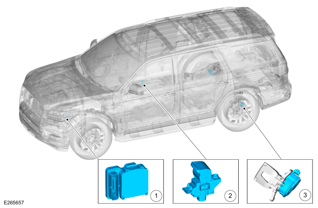
| 1 | ABS module |
| 2 | Parking brake switch |
| 3 | Parking brake actuator motor (2 required) |

 Parking Brake - Overview. Description and Operation
Overview
The parking brake system uses 2 switch activated, ECU controlled motors to apply and release the rear brake calipers. The ABS
module controls and monitors the parking brake system and sets
Diagnostic Trouble Codes (DTCs) when a fault is present in the system...
Other information:
Lincoln Navigator 2018-2026 Workshop Manual: Degas Bottle. Removal and Installation
Special Tool(s) / General Equipment Fluid Suction Gun Hose Clamp Remover/Installer Locking Pliers Materials Name Specification Motorcraft® Yellow Concentrated Antifreeze/CoolantVC-13-G WSS-M97B57-A1 Motorcraft® Orange Concentrated Antifreeze/CoolantVC-3-B WSS-M97B44-D Removal WARNING: Alway..
Lincoln Navigator 2018-2026 Workshop Manual: Tire Pressure Monitoring System (TPMS) - Component Location. Description and Operation
Item Description 1 RTM 2 BCM 3 TPMS sensor assembly (4 required) ..
Categories
- Manuals Home
- 4th Gen Lincoln Navigator Service Manual (2018 - 2026)
- Front Seat. Removal and Installation
- Brake Service Mode Activation and Deactivation. General Procedures
- Liftgate Trim Panel. Removal and Installation
- Telematics Control Unit (TCU) Module. Removal and Installation
- Vehicle Dynamics Control Module (VDM). Removal and Installation
Rear Stabilizer Bar Link. Removal and Installation
Removal
NOTE: Removal steps in this procedure may contain installation details.
With the vehicle in NEUTRAL, position it on a hoist.Refer to: Jacking and Lifting (100-02 Jacking and Lifting, Description and Operation).
NOTE: Use the hex-holding feature to prevent the stud from turning while removing the nut.
Remove and discard the 2 rear stabilizer bar link nuts and remove the rear stabilizer bar link.Torque: 46 lb.ft (63 Nm)
