Lincoln Navigator: Second Row Seats / Power Fold Seat Control Switch. Removal and Installation
Special Tool(s) /
General Equipment
| Flat-Bladed Screwdriver |
| Interior Trim Remover |
Removal
Vehicles with long wheelbase
-
Remove the D-pillar trim panel.
Refer to: D-Pillar Trim Panel - Long Wheelbase (501-05 Interior Trim and Ornamentation, Removal and Installation).
Vehicles with short wheelbase
-
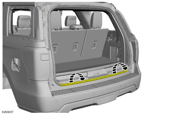
Position the liftgate opening weatherstrip aside.
-
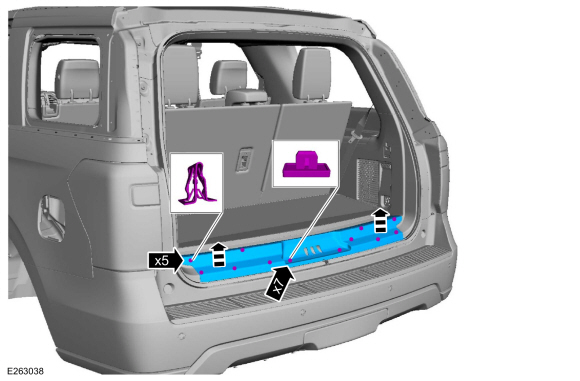
Release the clips and the liftgate scuff plate trim panel.
-
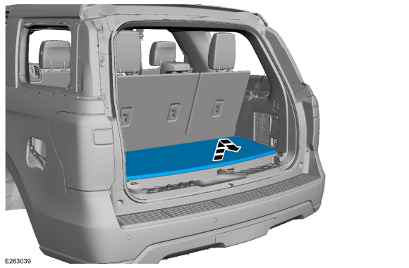
Remove the load floor cover.
-
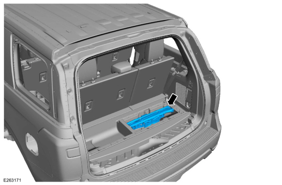
Position the load floor storage compartment cover up.
-
Remove the vehicle jack assembly.
-
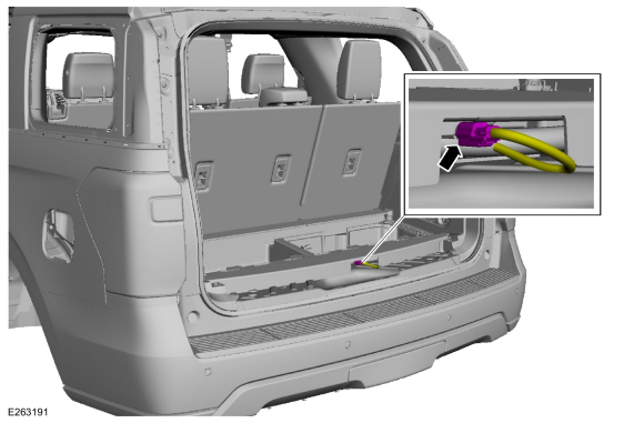
Disconnect the keyless entry rear antenna electrical connector.
-
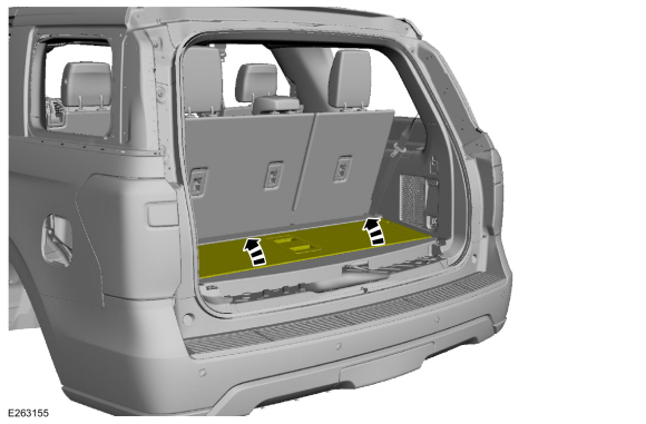
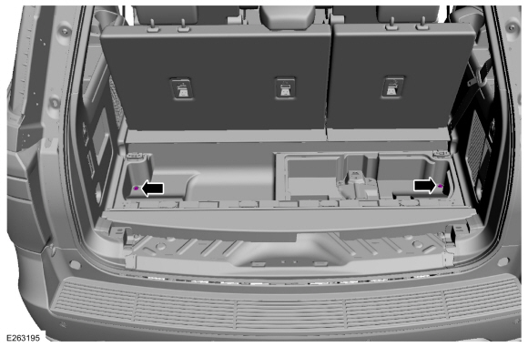
Remove the load floor storage compartment bolts.
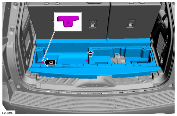
-
Release the clips and remove the load floor storage compartment.
-
Position the third row outer seatbelt retractor guide cover aside.
Use the General Equipment: Interior Trim Remover
-
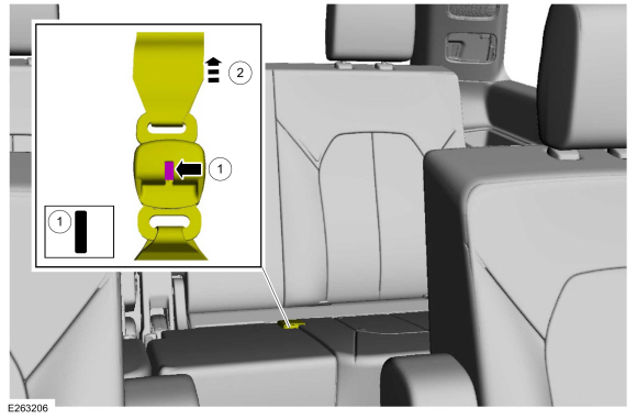
Disconnect the third row center seatbelt from the third row center seatbelt retractor mini-buckle.
-
Press the release button.
Use the General Equipment: Flat-Bladed Screwdriver
-
Release the third row center seatbelt retractor.
-
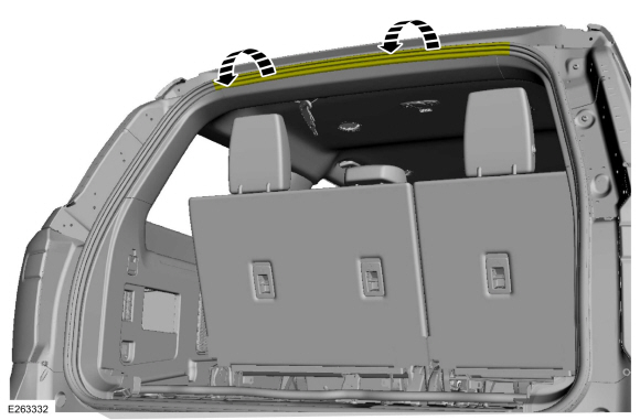
Position the liftgate opening weatherstrip aside.
-
Release the clips and remove the liftgate opening upper trim panel.
-
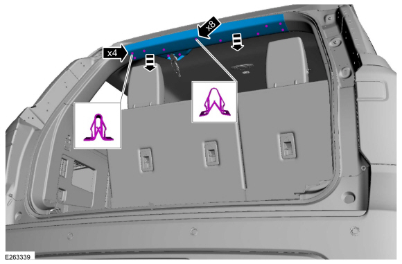
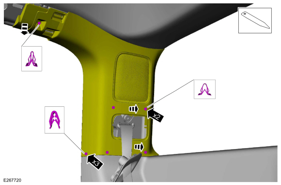
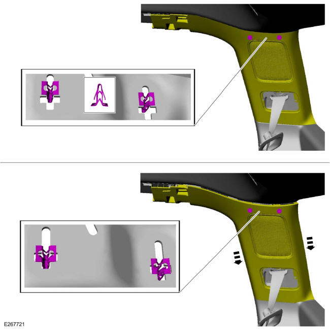
Release the D-pillar trim panel clips.
-
NOTICE:
The D-pillar trim panel must be positioned
downward to allow the upper clips to release correctly. Failure to
follow this direction may cause damage to the D-pillar trim panel.
Slide the D-pillar trim panel down, aligning the clips to the slots in the sheet metal.
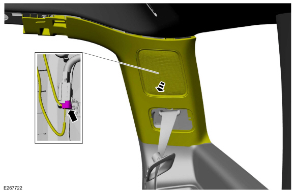
-
Position the D-pillar trim panel aside.
-
If equipped.
Disconnect the D-pillar speaker electrical connector.
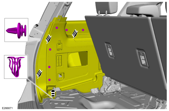
All vehicles
NOTE:
Short wheelbase shown, long wheelbase similar.
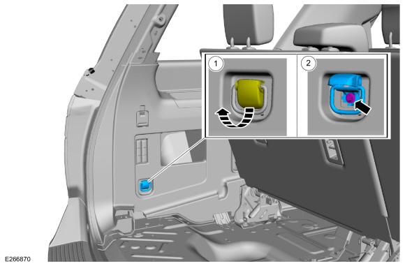
-
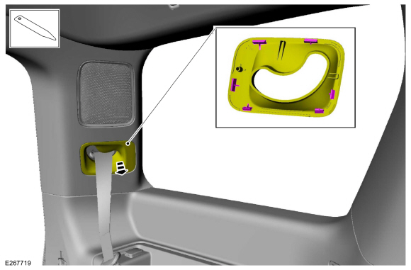
Remove the interior tie down hook.
-
Position the interior tie down hook bolt cover up.
-
Remove the bolt.
-
Release the retainers and position the loadspace
trim panel out enough to access the power fold seat control switch.
-
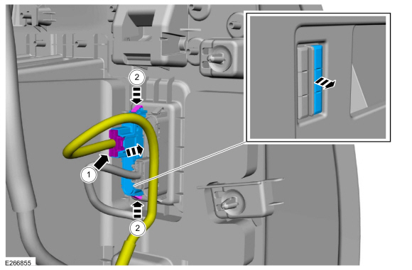
Remove the power fold seat control switch.
-
Disconnect the electrical connector.
-
Release the tabs.
Installation
-
To install, reverse the removal procedure.
DTC Chart: SCMC
Diagnostics in this manual assume a certain skill level and knowledge of Ford-specific diagnostic practices. REFER to: Diagnostic Methods (100-00 General Information, Description and Operation)...
Removal
WARNING:
The following procedure describes critical repair steps
required for correct seat component installation. Follow all notes and
steps carefully...
Other information:
Activation
Phase 1 - Leak Verification
Run the EVAP Test with the scan tool.
NOTE:
Some small leaks may not be detected using the EVAP Test. If the system
has passed the test but a leak is still suspected, then proceed to
Phase 2...
Diagnostic Trouble Code (DTC) Chart
Diagnostics in this manual assume a certain skill level and knowledge of Ford-specific diagnostic practices. REFER to: Diagnostic Methods (100-00 General Information, Description and Operation).
Diagnostic Trouble Code Chart
Module
DTC
Description
Action
..
 Second Row Seats. Diagnosis and Testing
 Second Row Center Seat. Removal and Installation
 205-123
(T78P-1177-A)
205-123
(T78P-1177-A)
 308-047
(T77F-1102-A)
308-047
(T77F-1102-A)