Lincoln Navigator: Roof Sheet Metal Repairs / Roof Side Rail. Removal and Installation
Special Tool(s) / General Equipment
| 6.5 mm Drill Bit | |
| Polydrive Bit Socket | |
| Self-Piercing Rivet (SPR) Remover/Installer | |
| Belt Sander | |
| Blind Rivet Gun | |
| Locking Pliers |
Materials
| Name | Specification |
|---|---|
| Metal Bonding Adhesive TA-1, TA-1-B, 3M™ 08115, LORD Fusor® 108B, Henkel Teroson EP 5055 |
- |
| Seam Sealer TA-2-B, 3M™ 08308, LORD Fusor® 803DTM |
- |
| Flexible Foam Repair 3M™ 08463, LORD Fusor® 121 |
- |
Removal
NOTE: Aluminum body panels are highly receptive to heat transfer. With the extensive use of structural adhesives and non-structural sealers used in vehicle construction, the potential of heat transfer could impact adhesives and sealers in non-associated panels during the repair process. Many repairs areas that utilize structural adhesive may be separated after fastener removal by using a panel chisel along the joint/flange. Using heat not exceeding 425° F to loosen a bonded panel should only be done when all panels in the joint will be replaced and new adhesive applied.
-
Verify the vehicle is dimensionally correct.
Refer to: Body and Frame (501-26 Body Repairs - Vehicle Specific Information and Tolerance Checks, Description and Operation).
-
Depower the SRS
Refer to: Supplemental Restraint System (SRS) Depowering (501-20B Supplemental Restraint System, General Procedures).
-
Remove the front fender on the affected side.
Refer to: Fender (501-02 Front End Body Panels, Removal and Installation).
-
Remove the front and rear door on the affected side.
Refer to: Front Door (501-03 Body Closures, Removal and Installation).
Refer to: Rear Door (501-03 Body Closures, Removal and Installation).
-
Remove the instrument panel.
Refer to: Instrument Panel (501-12 Instrument Panel and Console, Removal and Installation).
-
Remove the outer roof panel.
Refer to: Roof Panel (501-28 Roof Sheet Metal Repairs, Removal and Installation).
Refer to: Roof Panel - Vehicles With: Roof Opening Panel (501-28 Roof Sheet Metal Repairs, Removal and Installation).
-
Remove the A-pillar outer panel and reinforcement.
Refer to: A-Pillar Outer Panel Section and Reinforcement (501-29 Side Panel Sheet Metal Repairs, Removal and Installation).
NOTE: LH side shown, RH side similar.
-
Remove the B-pillar.
Refer to: B-Pillar Outer Panel (501-29 Side Panel Sheet Metal Repairs, Removal and Installation).
-
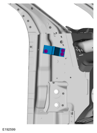
Remove the quarter panel.
-
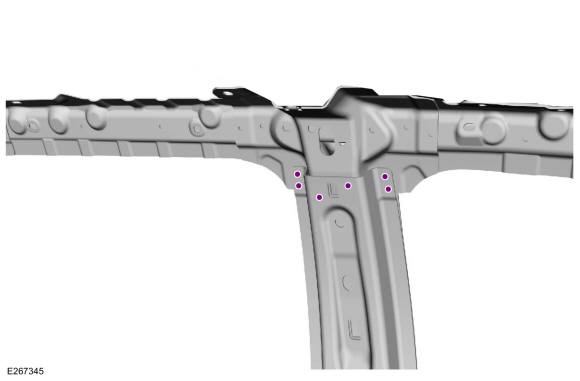
Remove the bolts and cross-car beam bracket.
 |
-
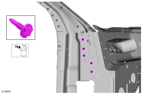
Remove and discard the FDS fasteners.
Use the General Equipment: Polydrive Bit Socket
 |
-
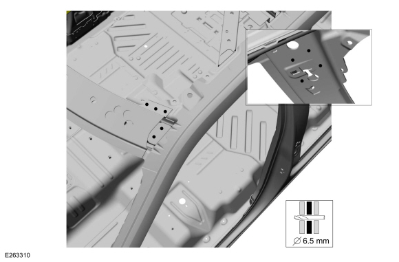
Remove the SPR fasteners and position aside the windshield header panel.
Use the General Equipment: Self-Piercing Rivet (SPR) Remover/Installer
Use the General Equipment: Belt Sander
 |
-
NOTE: Vehicles without roof opening panel.
Remove the SPR fasteners and position aside the roof reinforcement.
Use the General Equipment: Self-Piercing Rivet (SPR) Remover/Installer
Use the General Equipment: Belt Sander
 |
-
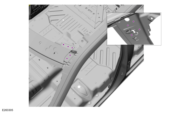
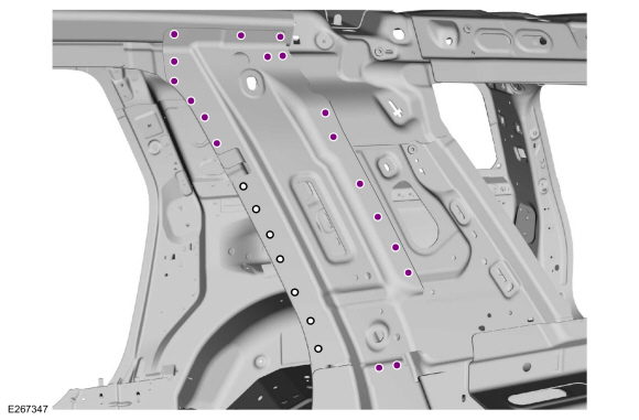
Remove the SPR fasteners from the upper B-pillar.
Use the General Equipment: Self-Piercing Rivet (SPR) Remover/Installer
Use the General Equipment: Belt Sander
 |
-
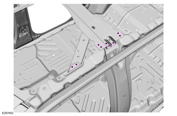
Remove and discard the FDS fasteners and SPR fasteners from the quarter panel upper reinforcement.
Use the General Equipment: Polydrive Bit Socket
Use the General Equipment: Self-Piercing Rivet (SPR) Remover/Installer
Use the General Equipment: Belt Sander
 |
-
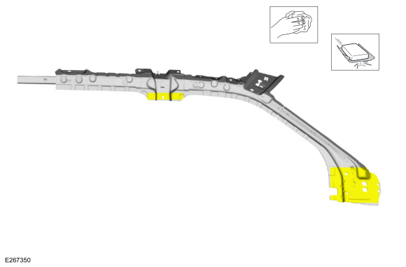
Remove the quarter panel upper reinforcement.
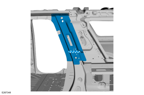 |
-
NOTE: Vehicle without roof opening panel shown, vehicles with roof opening panel similar.
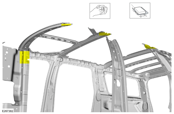
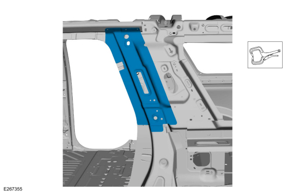
Remove the roof side rail assembly.
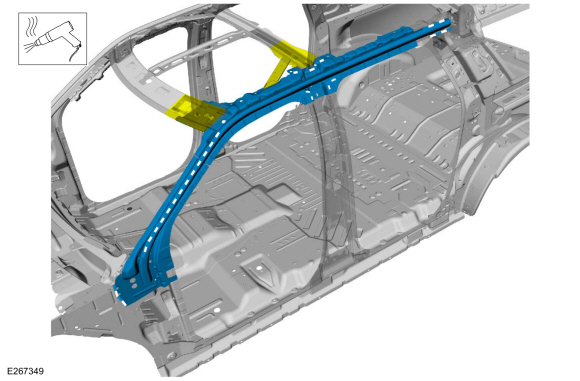 |
Installation
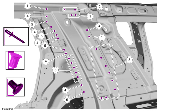
NOTE: SPR fasteners may not be placed directly over original SPR location. They must be placed adjacent to original location matching original quantity.
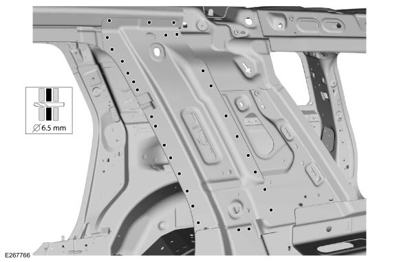
NOTE: Solid rivets or blind rivet fasteners may be used in place of SPR fasteners in original SPR location after enlarging hole to 6.5mm.
-
NOTE: Vehicles without roof opening panel shown, vehicles with roof opening panel shown.
Sand the mating surfaces to remove old adhesive using 80 grit sandpaper and clean.
 |
-
Sand the mating surfaces of the replacement rail to remove e-coat using 80 grit sandpaper and clean.
 |
-
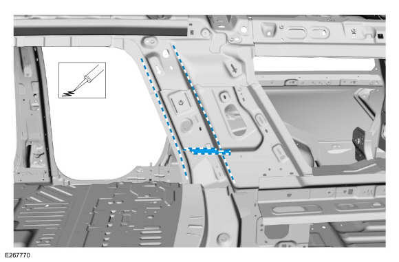
Apply adhesive to the mating areas.
Material: Metal Bonding Adhesive / TA-1, TA-1-B, 3M™ 08115, LORD Fusor® 108B, Henkel Teroson EP 5055
 |
-
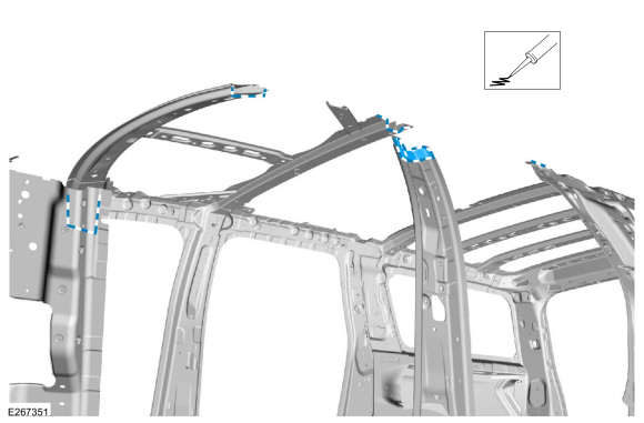
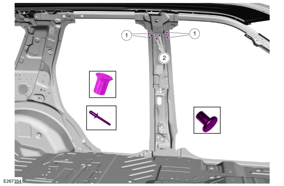
Install, clamp in position and apply NVH foam along the roof side rail as indicated.
Use the General Equipment: Locking Pliers
Material: Flexible Foam Repair / 3M™ 08463, LORD Fusor® 121
 |
-
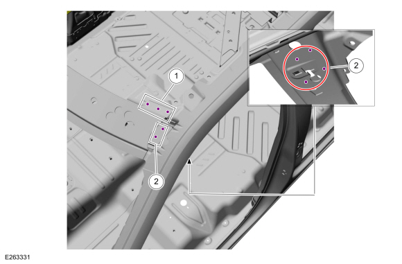
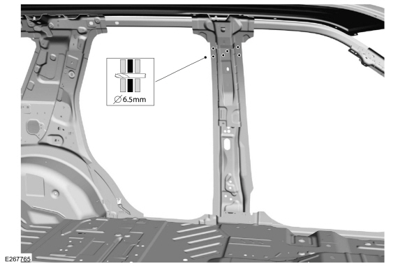
Position the windshield header panel, clamp in position and drill as indicated.
Use the General Equipment: 6.5 mm Drill Bit
 |
-
NOTE: SPR fasteners may not be placed directly over original SPR location. They must be placed adjacent to original location matching original quantity.
NOTE: Solid rivets or blind rivet fasteners may be used in place of SPR fasteners in original SPR location after enlarging hole to 6.5mm.
Install the fasteners.Item SPR Number SPR Code Henrob® Mandrel Pro-Spot® Mandrel Blind Rivet Solid Rivet Rivnut® 1 - - - - W708777-S900C - - 2 W710246-S900 BN DP10-200/H SA-0400/SA-0402 - W790377-S900 -
Refer to: Joining Techniques (501-25 Body Repairs - General Information, General Procedures).
Use the General Equipment: Self-Piercing Rivet (SPR) Remover/Installer
Use the General Equipment: Blind Rivet Gun
 |
-
NOTE: Vehicles without roof opening panel.
Position, clamp and drill holes for rivets in the roof reinforcement.
Use the General Equipment: 6.5 mm Drill Bit
 |
-
NOTE: SPR fasteners may not be placed directly over original SPR location. They must be placed adjacent to original location matching original quantity.
NOTE: Solid rivets or blind rivet fasteners may be used in place of SPR fasteners in original SPR location after enlarging hole to 6.5mm.
Install the fasteners.
Use the General Equipment: Blind Rivet GunItem SPR Number SPR Code Henrob® Mandrel Pro-Spot® Mandrel Blind Rivet Solid Rivet Rivnut® 1 - - - - W708777-S900C - - 2 - - - - W707638-SP00C - -
 |
-
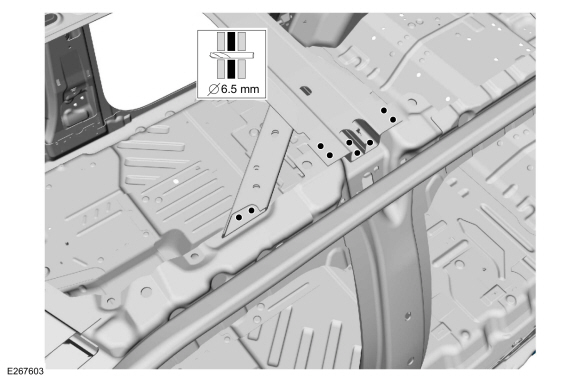
Clamp b-pillar in place and drill for rivets.
Use the General Equipment: 6.5 mm Drill Bit
 |
-
NOTE: SPR fasteners may not be placed directly over original SPR location. They must be placed adjacent to original location matching original quantity.
NOTE: Solid rivets or blind rivet fasteners may be used in place of SPR fasteners in original SPR location after enlarging hole to 6.5mm.
From the outside install the fasteners at the upper b-pillar.
Use the General Equipment: Locking PliersItem SPR Number SPR Code Henrob® Mandrel Pro-Spot® Mandrel Blind Rivet Solid Rivet Rivnut® 1 W717186-S900 EN DG11-200/H SA-0400/SA-0401 - W790376-S900 - 2 - - - - W708777-S900C - -
Use the General Equipment: 6.5 mm Drill Bit
 |
-
Sand and clean mating surface with 80 grit sand paper to remove old adhesive.
 |
-
Apply adhesive and NVH foam to the mating surface.
Material: Metal Bonding Adhesive / TA-1, TA-1-B, 3M™ 08115, LORD Fusor® 108B, Henkel Teroson EP 5055
Material: Flexible Foam Repair / 3M™ 08463, LORD Fusor® 121
 |
-
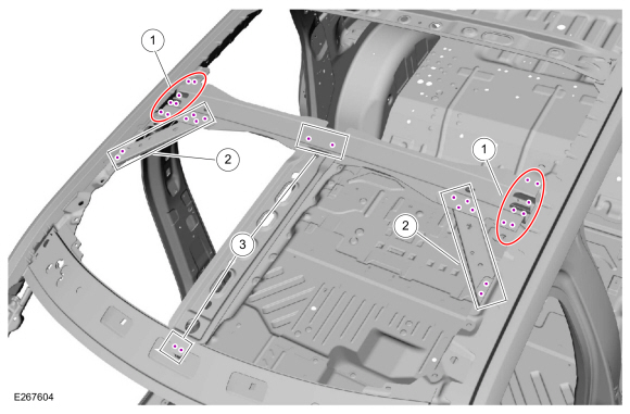
Position and clamp the C-pillar upper reinforcement and apply NVH foam (obtain locally) as indicated.
Use the General Equipment: Locking Pliers
Material: Flexible Foam Repair / 3M™ 08463, LORD Fusor® 121
 |
-
Drill for rivets.
Use the General Equipment: 6.5 mm Drill Bit
 |
-
NOTE: SPR fasteners may not be placed directly over original SPR location. They must be placed adjacent to original location matching original quantity.
NOTE: Solid rivets or blind rivet fasteners may be used in place of SPR fasteners in original SPR location after enlarging hole to 6.5mm.
Install the fasteners.
Use the General Equipment: Blind Rivet GunItem SPR Number SPR Code Henrob® Mandrel Pro-Spot® Mandrel Blind Rivet Solid Rivet Rivnut® 1 - - - - W708777-S900C - - 2 - - - - W702554-S900C - - 3 - - - - W702512-S900C - - 4 W7122218-S900 DB DZ09-025/H SA-0400/SA-0401 - W790376-S900 - 5 W708717-S900 AW DP11-200/H SA-0400/SA-0402 - W790377-S900 -
 |
-
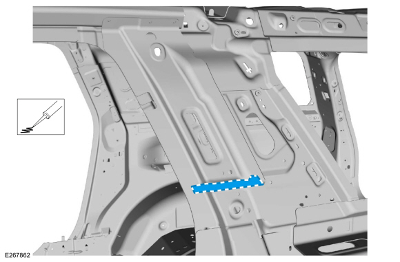
Apply NVH foam as indicated.
Material: Flexible Foam Repair / 3M™ 08463, LORD Fusor® 121
 |
-
Install the A-pillar reinforcement.
Refer to: A-Pillar Outer Panel Section and Reinforcement (501-29 Side Panel Sheet Metal Repairs, Removal and Installation).
-
Install the quarter panel.
-
Install the B-pillar.
Refer to: B-Pillar and Reinforcement (501-29 Side Panel Sheet Metal Repairs, Removal and Installation).
-
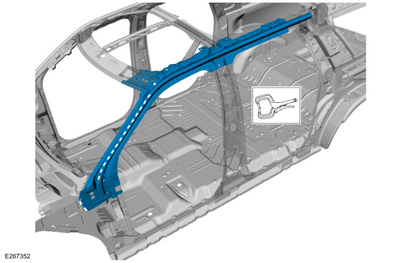
Install the roof outer panel.
Refer to: Roof Panel (501-28 Roof Sheet Metal Repairs, Removal and Installation).
Refer to: Roof Panel - Vehicles With: Roof Opening Panel (501-28 Roof Sheet Metal Repairs, Removal and Installation).
-
Metal finish the repair areas using typical repair techniques.
-
Seam sealing: All seams must be sealed to production level.
Material: Seam Sealer / TA-2-B, 3M™ 08308, LORD Fusor® 803DTM
-
NOTE: Solid rivets or blind rivet fasteners may be used in place of SPR fasteners in original SPR location after enlarging hole to 6.5mm.
Enlarge existing FDS holes as indicated.
Use the General Equipment: 6.5 mm Drill Bit
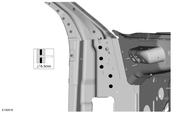 |
-
NOTE: SPR fasteners may not be placed directly over original SPR location. They must be placed adjacent to original location matching original quantity.
NOTE: Solid rivets or blind rivet fasteners may be used in place of SPR fasteners in original SPR location after enlarging hole to 6.5mm.
Install the fasteners.Item SPR Number SPR Code Henrob® Mandrel Pro-Spot® Mandrel Blind Rivet Solid Rivet Rivnut® 1 - - - - W702512-S900C - - 2 - - - - W708777-S900C - -
Refer to: Joining Techniques (501-25 Body Repairs - General Information, General Procedures).
Use the General Equipment: Blind Rivet Gun
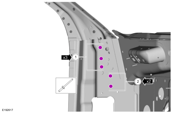 |
-
Refinish the repair area using a Ford approved paint system.
-
Install the cross-car beam bracket and bolts.
Torque: 18 lb.ft (25 Nm)
|
-
Install the instrument panel.
Refer to: Instrument Panel (501-12 Instrument Panel and Console, Removal and Installation).
-
Install the front and rear doors.
Refer to: Front Door (501-03 Body Closures, Removal and Installation).
Refer to: Rear Door (501-03 Body Closures, Removal and Installation).
-
Install the fender.
Refer to: Fender (501-02 Front End Body Panels, Removal and Installation).
-
Align the doors.
Refer to: Front Door Alignment (501-03 Body Closures, General Procedures).
Refer to: Rear Door Alignment (501-03 Body Closures, General Procedures).
-
Repower the SRS
Refer to: Supplemental Restraint System (SRS) Repowering (501-20B Supplemental Restraint System, General Procedures).

 Roof Side Rail Section. Removal and Installation
Special Tool(s) /
General Equipment
6.5 mm Drill Bit
Polydrive Bit Socket
Self-Piercing Rivet (SPR) Remover/Installer
Belt Sander
Blind Rivet Gun
Air Body Saw
MIG/MAG Welding Equipment
Locking Pliers
Materials
Name
Specification
Metal Bonding AdhesiveTA-1, TA-1-B, 3M™ 08115, LORD Fusor® 108B, Henkel Teroson ..
Other information:
Lincoln Navigator 2018-2026 Workshop Manual: Steering Wheel and Column Electrical Components. Diagnosis and Testing
Diagnostic Trouble Code (DTC) Chart Diagnostics in this manual assume a certain skill level and knowledge of Ford-specific diagnostic practices. REFER to: Diagnostic Methods (100-00 General Information, Description and Operation). Module DTC Description Action BCM B108A:01 Start Button: General Electrical Failure GO to Pinpoint Test A BCM B108A:24 Start..
Lincoln Navigator 2018-2026 Workshop Manual: Steering Gear Boot. Removal and Installation
Special Tool(s) / General Equipment Boot Clamp Pliers Materials Name Specification Motorcraft® Premium Long-Life GreaseXG-1-E1 ESA-M1C75-B Removal Remove the tie-rod end. Refer to: Tie Rod End (211-02 Power Steering, Removal and Installation). NOTE: Count and record the number of turns required to remo..
Categories
- Manuals Home
- 4th Gen Lincoln Navigator Service Manual (2018 - 2026)
- Power Running Board (PRB). Diagnosis and Testing
- Transmission Fluid Drain and Refill. General Procedures
- Identification Codes. Description and Operation
- SYNC Module [APIM]. Removal and Installation
- Body and Paint
Front Driveshaft. Removal and Installation
Special Tool(s) / General Equipment
Crimping ToolMaterials
Name Specification Motorcraft® Premium Long-Life GreaseXG-1-E1 ESA-M1C75-B
Removal
With the vehicle in NEUTRAL, position the vehicle on a hoist.Refer to: Jacking and Lifting (100-02 Jacking and Lifting, Description and Operation).
Remove the bolts and the transmission shield.