Lincoln Navigator: Handles, Locks, Latches and Entry Systems / Locks, Latches and Entry Systems. Diagnosis and Testing
DTC Chart: BCM
Diagnostics in this manual assume a certain skill level and knowledge of Ford-specific diagnostic practices.
REFER to: Diagnostic Methods (100-00 General Information, Description and Operation).
| DTC | Description | Action |
|---|---|---|
| B10AB:00 | Remote Keyless Entry Synchronization: No Sub Type Information | GO to Pinpoint Test Q |
| B10C6:01 | Exterior Trunk Antenna: General Electrical Failure | GO to Pinpoint Test X |
| B10C7:01 | Interior Trunk Antenna: General Electrical Failure | GO to Pinpoint Test V |
| B1218:00 | Transmitter Identification Code: No Sub Type Information | GO to Pinpoint Test Q |
| B121A:11 | Keypad Illumination Output: Circuit Short To Ground | GO to Pinpoint Test M |
| B121A:15 | Keypad Illumination Output: Circuit Short To Battery or Open |
|
| B121B:01 | Keypad Input Switch: General Electrical Failure | GO to Pinpoint Test O |
| B12E8:11 | Liftgate/Tailgate Control/Release Switch: Circuit Short To Ground |
REFER to: Body Closures (501-03 Body Closures, Diagnosis and Testing). |
| B1336:01 | Left Front Door External Antenna: General Electrical Failure | GO to Pinpoint Test U |
| B1337:01 | Right Front Door External Antenna: General Electrical Failure | GO to Pinpoint Test U |
| B1381:11 | Left Front Door Handle Proximity Sensor: Circuit Short To Ground | GO to Pinpoint Test U |
| B1381:15 | Left Front Door Handle Proximity Sensor: Circuit Short To Battery or Open | GO to Pinpoint Test U |
| B1381:29 | Left Front Door Handle Proximity Sensor: Signal Invalid | GO to Pinpoint Test U |
| B1382:11 | Right Front Door Handle Proximity Sensor: Circuit Short To Ground | GO to Pinpoint Test U |
| B1382:15 | Right Front Door Handle Proximity Sensor: Circuit Short To Battery or Open | GO to Pinpoint Test U |
| B1382:29 | Right Front Door Handle Proximity Sensor: Signal Invalid | GO to Pinpoint Test U |
| B1383:11 | Left Rear Door Handle Proximity Sensor: Circuit Short To Ground | GO to Pinpoint Test U |
| B1383:15 | Left Rear Door Handle Proximity Sensor: Circuit Short To Battery or Open | GO to Pinpoint Test U |
| B1383:29 | Left Rear Door Handle Proximity Sensor: Signal Invalid | GO to Pinpoint Test U |
| B1384:11 | Right Rear Door Handle Proximity Sensor: Circuit Short To Ground | GO to Pinpoint Test U |
| B1384:15 | Right Rear Door Handle Proximity Sensor: Circuit Short To Battery or Open | GO to Pinpoint Test U |
| B1384:29 | Right Rear Door Handle Proximity Sensor: Signal Invalid | GO to Pinpoint Test U |
| B14B8:11 | Sounder: Circuit Short To Ground | GO to Pinpoint Test Z |
| B14B8:15 | Sounder: Circuit Short To Battery or Open |
|
| B1584:11 | Decklid/Liftglass Release Output: Circuit Short To Ground | GO to Pinpoint Test AG |
| B1584:12 | Decklid/Liftglass Release Output: Circuit Short To Battery | GO to Pinpoint Test AG |
| B1584:13 | Decklid/Liftglass Release Output: Circuit Open | GO to Pinpoint Test AG |
| C1017:11 | Boot/Trunk Primary Switch: Circuit Short To Ground | GO to Pinpoint Test AG |
| U0258:87 | Lost Communication With Radio Transceiver: Missing Message | GO to Pinpoint Test AF |
| All other Diagnostic Trouble Codes (DTCs) | - |
REFER to: Body Control Module (BCM) (419-10 Multifunction Electronic Modules, Diagnosis and Testing). |
DTC Chart: DDM
Diagnostics in this manual assume a certain skill level and knowledge of Ford-specific diagnostic practices.
REFER to: Diagnostic Methods (100-00 General Information, Description and Operation).
| DTC | Description | Action |
|---|---|---|
| B1087:83 | LIN Bus "A": Value of Signal Protection Calculation Incorrect |
REFER to: Glass, Frames and Mechanisms (501-11 Glass, Frames and Mechanisms, Diagnosis and Testing). |
| B1087:87 | LIN Bus "A": Missing Message |
REFER to: Glass, Frames and Mechanisms (501-11 Glass, Frames and Mechanisms, Diagnosis and Testing). |
| B108F:23 | Cabin Lock/Unlock Switch: Signal Stuck Low | GO to Pinpoint Test K |
| B1163:11 | Left Mirror Heater Output: Circuit Short To Ground |
REFER to: Rear View Mirrors (501-09 Rear View Mirrors, Diagnosis and Testing). |
| B1163:15 | Left Mirror Heater Output: Circuit Short To Battery or Open |
REFER to: Rear View Mirrors (501-09 Rear View Mirrors, Diagnosis and Testing). |
| B1163:4B | Left Mirror Heater Output: Over Temperature |
REFER to: Rear View Mirrors (501-09 Rear View Mirrors, Diagnosis and Testing). |
| B1165:11 | Left Front Puddle Lamp Output: Circuit Short To Ground |
REFER to: Interior Lighting (417-02 Interior Lighting, Diagnosis and Testing). |
| B1165:15 | Left Front Puddle Lamp Output: Circuit Short To Battery or Open |
REFER to: Interior Lighting (417-02 Interior Lighting, Diagnosis and Testing). |
| B117C:11 | Rear Power Window Up: Circuit Short to Ground |
REFER to: Glass, Frames and Mechanisms (501-11 Glass, Frames and Mechanisms, Diagnosis and Testing). |
| B117C:12 | Rear Power Window Up: Circuit Short to Battery |
REFER to: Glass, Frames and Mechanisms (501-11 Glass, Frames and Mechanisms, Diagnosis and Testing). |
| B117C:13 | Rear Power Window Up: Circuit Current Open |
REFER to: Glass, Frames and Mechanisms (501-11 Glass, Frames and Mechanisms, Diagnosis and Testing). |
| B117C:19 | Rear Power Window Up: Circuit Current Above Threshold |
REFER to: Glass, Frames and Mechanisms (501-11 Glass, Frames and Mechanisms, Diagnosis and Testing). |
| B117E:11 | Front Power Window Up: Circuit Short To Ground |
REFER to: Glass, Frames and Mechanisms (501-11 Glass, Frames and Mechanisms, Diagnosis and Testing). |
| B117E:12 | Front Power Window Up: Circuit Short To Battery |
REFER to: Glass, Frames and Mechanisms (501-11 Glass, Frames and Mechanisms, Diagnosis and Testing). |
| B117E:13 | Front Power Window Up: Circuit Open |
REFER to: Glass, Frames and Mechanisms (501-11 Glass, Frames and Mechanisms, Diagnosis and Testing). |
| B117E:19 | Front Power Window Up: Circuit Current Above Threshold |
REFER to: Glass, Frames and Mechanisms (501-11 Glass, Frames and Mechanisms, Diagnosis and Testing). |
| B117F:19 | Front Power Window Down: Circuit Current Above Threshold |
REFER to: Glass, Frames and Mechanisms (501-11 Glass, Frames and Mechanisms, Diagnosis and Testing). |
| B1189:29 | Front Window Position Sensor: Signal Invalid |
REFER to: Glass, Frames and Mechanisms (501-11 Glass, Frames and Mechanisms, Diagnosis and Testing). |
| B118A:29 | Rear Window Position Sensor: Signal Invalid |
REFER to: Glass, Frames and Mechanisms (501-11 Glass, Frames and Mechanisms, Diagnosis and Testing). |
| B118C:11 | Left Blind Spot Warning Indicator: Circuit Short To Ground |
REFER to: Blind Spot Information System (419-04A Side and Rear Vision, Diagnosis and Testing). |
| B118C:15 | Left Blind Spot Warning Indicator: Circuit Short To Battery or Open |
REFER to: Blind Spot Information System (419-04A Side and Rear Vision, Diagnosis and Testing). |
| B11F6:11 | Driver Folding Mirror Motor: Circuit Short To Ground |
REFER to: Rear View Mirrors (501-09 Rear View Mirrors, Diagnosis and Testing). |
| B11F6:15 | Driver Folding Mirror Motor: Circuit Short To Battery or Open |
REFER to: Rear View Mirrors (501-09 Rear View Mirrors, Diagnosis and Testing). |
| B12BA:11 | Lock Status LED Front: Circuit Short To Ground | GO to Pinpoint Test H |
| B12DC:21 | Front Window Motion/Position Sensor: Signal Amplitude < Minimum |
REFER to: Glass, Frames and Mechanisms (501-11 Glass, Frames and Mechanisms, Diagnosis and Testing). |
| B12DC:31 | Front Window Motion/Position Sensor: No Signal |
REFER to: Glass, Frames and Mechanisms (501-11 Glass, Frames and Mechanisms, Diagnosis and Testing). |
| B12DD:21 | Front Window Motion/Position Sensor: Signal Amplitude < Minimum |
REFER to: Glass, Frames and Mechanisms (501-11 Glass, Frames and Mechanisms, Diagnosis and Testing). |
| B12DD:31 | Front Window Motion/Position Sensor: No Signal |
REFER to: Glass, Frames and Mechanisms (501-11 Glass, Frames and Mechanisms, Diagnosis and Testing). |
| B12E9:23 | Rear Window Local Up/Down Switch: Signal Stuck Low |
REFER to: Glass, Frames and Mechanisms (501-11 Glass, Frames and Mechanisms, Diagnosis and Testing). |
| B13F0:4B | Left Rear Power Window Motor: Over Temperature |
REFER to: Glass, Frames and Mechanisms (501-11 Glass, Frames and Mechanisms, Diagnosis and Testing). |
| B13F1:4B | Driver Power Window Motor: Over Temperature |
REFER to: Glass, Frames and Mechanisms (501-11 Glass, Frames and Mechanisms, Diagnosis and Testing). |
| B1C03:23 | Memory #1 Switch: Signal Stuck Low |
REFER to: Front Seats (501-10A Front Seats, Diagnosis and Testing). |
| B1C04:23 | Memory #2 Switch: Signal Stuck Low |
REFER to: Front Seats (501-10A Front Seats, Diagnosis and Testing). |
| B1C05:23 | Memory #3 Switch: Signal Stuck Low |
REFER to: Front Seats (501-10A Front Seats, Diagnosis and Testing). |
| B1C09:11 | Driver Left/Right Mirror Motor: Circuit Short To Ground |
REFER to: Rear View Mirrors (501-09 Rear View Mirrors, Diagnosis and Testing). |
| B1C10:11 | Driver Up/Down Mirror Motor: Circuit Short To Ground |
REFER to: Rear View Mirrors (501-09 Rear View Mirrors, Diagnosis and Testing). |
| B1C13:11 | Driver Up/Down Mirror Motor Feedback: Circuit Short To Ground |
REFER to: Rear View Mirrors (501-09 Rear View Mirrors, Diagnosis and Testing). |
| B1C13:15 | Driver Up/Down Mirror Motor Feedback: Circuit Short To Battery or Open |
REFER to: Rear View Mirrors (501-09 Rear View Mirrors, Diagnosis and Testing). |
| B1C14:11 | Driver Left/Right Mirror Motor Feedback: Circuit Short To Ground |
REFER to: Rear View Mirrors (501-09 Rear View Mirrors, Diagnosis and Testing). |
| B1C14:15 | Driver Left/Right Mirror Motor Feedback: Circuit Short To Battery or Open |
REFER to: Rear View Mirrors (501-09 Rear View Mirrors, Diagnosis and Testing). |
| B1D06:11 | Left Turn Indicator: Circuit Short To Ground |
REFER to: Turn Signal and Hazard Lamps (417-01 Exterior Lighting, Diagnosis and Testing). |
| B1D06:15 | Left Turn Indicator: Circuit Short To Battery or Open |
REFER to: Turn Signal and Hazard Lamps (417-01 Exterior Lighting, Diagnosis and Testing). |
| C1B15:11 | Sensor Supply Voltage B: Circuit Short To Ground |
REFER to: Rear View Mirrors (501-09 Rear View Mirrors, Diagnosis and Testing). |
| C1B15:15 | Sensor Supply Voltage B: Circuit Short To Battery or Open |
REFER to: Rear View Mirrors (501-09 Rear View Mirrors, Diagnosis and Testing). |
| U0140:00 | Lost Communication With Body Control Module: No Sub Type Information | GO to Pinpoint Test AB |
| U0164:00 | Lost Communication With HVAC Control Module: No Sub Type Information |
REFER to: Climate Control System (412-00 Climate Control System - General Information, Diagnosis and Testing). |
| U0208:00 | Lost Communication With Seat Control Module A: No Sub Type Information |
REFER to: Front Seats (501-10A Front Seats, Diagnosis and Testing). |
| U0232:00 | Lost Communication With Side Obstacle Detection Control Module - Left: No Sub Type Information | GO to Pinpoint Test AD |
| U0300:00 | Internal Control Module Software Incompatibility: No Sub Type Information |
CLEAR the Diagnostic Trouble Codes (DTCs) and REPEAT the self-test. If the DTC is retrieved again, INSTALL a new DDM . REFER to: Driver Door Module (DDM) (419-10 Multifunction Electronic Modules, Removal and Installation). |
| U0422:00 | Invalid Data Received From Body Control Module: No Sub Type Information |
RETRIEVE and FOLLOW Diagnostic Trouble Codes (DTCs) present in the BCM . REFER to: Body Control Module (BCM) (419-10 Multifunction Electronic Modules, Diagnosis and Testing). • If no Diagnostic Trouble Codes (DTCs) are present in the BCM , DIAGNOSE the observable symptom. |
| U0509:00 | Invalid Data Received From "Seat Control Module A": No Sub Type Information |
REFER to: Front Seats (501-10A Front Seats, Diagnosis and Testing). |
| U2013:23 | Switch Pack: Signal Stuck High |
REFER to: Glass, Frames and Mechanisms (501-11 Glass, Frames and Mechanisms, Diagnosis and Testing). |
| U201A:57 | Control Module Main Calibration Data: Invalid / Incompatible Software Component |
This DTC sets due to an incorrect or incomplete DDM configuration.
Using a diagnostic scan tool, PERFORM the DDM programming procedure
using as-built data. For information on as-built data, REFER to: Module Configuration - System Operation and Component Description (418-01A Module Configuration, Description and Operation). See: As-Built Data. |
| U2100:00 | Initial Configuration Not Complete: No Sub Type Information |
This DTC sets due to an incorrect or incomplete DDM configuration.
Using a diagnostic scan tool, PERFORM the DDM programming procedure
using as-built data. For information on as-built data, REFER to: Module Configuration - System Operation and Component Description (418-01A Module Configuration, Description and Operation). See: As-Built Data. |
| U2101:00 | Control Module Configuration Incompatible: No Sub Type Information |
This DTC sets due to an incorrect or incomplete DDM configuration.
Using a diagnostic scan tool, PERFORM the DDM programming procedure
using as-built data. For information on as-built data, REFER to: Module Configuration - System Operation and Component Description (418-01A Module Configuration, Description and Operation). See: As-Built Data. |
| U2200:00 | Control Module Configuration Memory Corrupt: No Sub Type Information |
INSTALL a new DDM . REFER to: Driver Door Module (DDM) (419-10 Multifunction Electronic Modules, Removal and Installation). |
| U3000:04 | Control Module: System Internal Failure |
INSTALL a new DDM . REFER to: Driver Door Module (DDM) (419-10 Multifunction Electronic Modules, Removal and Installation). |
| U3000:49 | Control Module: Internal Electronic Failure |
|
| U3000:4B | Control Module: Over Temperature |
|
| U3003:16 | Battery Voltage: Circuit Voltage Below Threshold | GO to Pinpoint Test AH |
| U3003:17 | Battery Voltage: Circuit Voltage Above Threshold | GO to Pinpoint Test AI |
DTC Chart: PCM
Diagnostics in this manual assume a certain skill level and knowledge of Ford-specific diagnostic practices.
REFER to: Diagnostic Methods (100-00 General Information, Description and Operation).
| DTC | Description | Action |
|---|---|---|
| P1594 | Forced Engine Shutdown - Remote Start System Fault, No Unattended Vehicle Timeout | GO to Pinpoint Test AA |
| P1595 | Forced Engine Shutdown - Remote Start System Fault, Transmission Range Not In Park Position | GO to Pinpoint Test AA |
| All other Diagnostic Trouble Codes (DTCs) | - | REFER to the PCM DTC Chart in the appropriate 303-14 section. |
DTC Chart: PDM
Diagnostics in this manual assume a certain skill level and knowledge of Ford-specific diagnostic practices.
REFER to: Diagnostic Methods (100-00 General Information, Description and Operation).
| DTC | Description | Action |
|---|---|---|
| B108F:23 | Cabin Lock/Unlock Switch: Signal Stuck Low | GO to Pinpoint Test K |
| B1164:11 | Right Mirror Heater Output: Circuit Short To Ground |
REFER to: Rear View Mirrors (501-09 Rear View Mirrors, Diagnosis and Testing). |
| B1164:15 | Right Mirror Heater Output: Circuit Short To Battery or Open |
REFER to: Rear View Mirrors (501-09 Rear View Mirrors, Diagnosis and Testing). |
| B1164:4B | Right Mirror Heater Output: Over Temperature |
REFER to: Rear View Mirrors (501-09 Rear View Mirrors, Diagnosis and Testing). |
| B1166:11 | Right Front Puddle Lamp Output: Circuit Short To Ground |
REFER to: Interior Lighting (417-02 Interior Lighting, Diagnosis and Testing). |
| B1166:15 | Right Front Puddle Lamp Output: Circuit Short To Battery or Open |
REFER to: Interior Lighting (417-02 Interior Lighting, Diagnosis and Testing). |
| B117C:11 | Rear Power Window Up: Circuit Short to Ground |
REFER to: Glass, Frames and Mechanisms (501-11 Glass, Frames and Mechanisms, Diagnosis and Testing). |
| B117C:12 | Rear Power Window Up: Circuit Short to Battery |
REFER to: Glass, Frames and Mechanisms (501-11 Glass, Frames and Mechanisms, Diagnosis and Testing). |
| B117C:13 | Rear Power Window Up: Circuit Open |
REFER to: Glass, Frames and Mechanisms (501-11 Glass, Frames and Mechanisms, Diagnosis and Testing). |
| B117C:19 | Rear Power Window Up: Circuit Current Above Threshold |
REFER to: Glass, Frames and Mechanisms (501-11 Glass, Frames and Mechanisms, Diagnosis and Testing). |
| B117E:11 | Front Power Window Up: Circuit Short To Ground |
REFER to: Glass, Frames and Mechanisms (501-11 Glass, Frames and Mechanisms, Diagnosis and Testing). |
| B117E:12 | Front Power Window Up: Circuit Short To Battery |
REFER to: Glass, Frames and Mechanisms (501-11 Glass, Frames and Mechanisms, Diagnosis and Testing). |
| B117E:13 | Front Power Window Up: Circuit Open |
REFER to: Glass, Frames and Mechanisms (501-11 Glass, Frames and Mechanisms, Diagnosis and Testing). |
| B117E:19 | Front Power Window Up: Circuit Current Above Threshold |
REFER to: Glass, Frames and Mechanisms (501-11 Glass, Frames and Mechanisms, Diagnosis and Testing). |
| B117F:19 | Front Power Window Down: Circuit Current Above Threshold |
REFER to: Glass, Frames and Mechanisms (501-11 Glass, Frames and Mechanisms, Diagnosis and Testing). |
| B118D:11 | Right Blind Spot Warning Indicator: Circuit Short To Ground |
REFER to: Blind Spot Information System (419-04A Side and Rear Vision, Diagnosis and Testing). |
| B118D:15 | Right Blind Spot Warning Indicator: Circuit Short To Battery or Open |
REFER to: Blind Spot Information System (419-04A Side and Rear Vision, Diagnosis and Testing). |
| B11F7:11 | Driver Folding Mirror Motor: Circuit Short To Ground |
REFER to: Rear View Mirrors (501-09 Rear View Mirrors, Diagnosis and Testing). |
| B11F7:15 | Driver Folding Mirror Motor: Circuit Short To Battery or Open |
REFER to: Rear View Mirrors (501-09 Rear View Mirrors, Diagnosis and Testing). |
| B12BA:11 | Lock Status LED Front: Circuit Short To Ground | GO to Pinpoint Test H |
| B12DC:21 | Front Window Motor Motion/Position Sensor: Signal Amplitude < Minimum |
REFER to: Glass, Frames and Mechanisms (501-11 Glass, Frames and Mechanisms, Diagnosis and Testing). |
| B12DC:31 | Front Window Motor Motion/Position Sensor: No Signal |
REFER to: Glass, Frames and Mechanisms (501-11 Glass, Frames and Mechanisms, Diagnosis and Testing). |
| B12DD:21 | Rear Window Motor Motion/Position Sensor: Signal Amplitude < Minimum |
REFER to: Glass, Frames and Mechanisms (501-11 Glass, Frames and Mechanisms, Diagnosis and Testing). |
| B12DD:31 | Rear Window Motor Motion/Position Sensor: No Signal |
REFER to: Glass, Frames and Mechanisms (501-11 Glass, Frames and Mechanisms, Diagnosis and Testing). |
| B12E9:23 | Rear Window Local Up/Down Switch: Signal Stuck Low |
REFER to: Glass, Frames and Mechanisms (501-11 Glass, Frames and Mechanisms, Diagnosis and Testing). |
| B13E5:23 | Passenger Power Window Switch Up |
REFER to: Glass, Frames and Mechanisms (501-11 Glass, Frames and Mechanisms, Diagnosis and Testing). |
| B13E6:23 | Passenger Power Window Switch Down |
REFER to: Glass, Frames and Mechanisms (501-11 Glass, Frames and Mechanisms, Diagnosis and Testing). |
| B13EF:4B | Right Rear Power Window Motor: Over Temperature |
REFER to: Glass, Frames and Mechanisms (501-11 Glass, Frames and Mechanisms, Diagnosis and Testing). |
| B13F0:4B | Left Rear Power Window Motor: Over Temperature |
REFER to: Glass, Frames and Mechanisms (501-11 Glass, Frames and Mechanisms, Diagnosis and Testing). |
| B13F2:4B | Passenger Power Window Motor: Over Temperature |
REFER to: Glass, Frames and Mechanisms (501-11 Glass, Frames and Mechanisms, Diagnosis and Testing). |
| B1C03:23 | Memory #1 Switch: Signal Stuck Low |
REFER to: Front Seats (501-10A Front Seats, Diagnosis and Testing). |
| B1C04:23 | Memory #2 Switch: Signal Stuck Low |
REFER to: Front Seats (501-10A Front Seats, Diagnosis and Testing). |
| B1C05:23 | Memory #3 Switch: Signal Stuck Low |
REFER to: Front Seats (501-10A Front Seats, Diagnosis and Testing). |
| B1C09:11 | Driver Left/Right Mirror Motor: Circuit Short To Ground |
REFER to: Rear View Mirrors (501-09 Rear View Mirrors, Diagnosis and Testing). |
| B1C10:11 | Driver Up/Down Mirror Motor: Circuit Short To Ground |
REFER to: Rear View Mirrors (501-09 Rear View Mirrors, Diagnosis and Testing). |
| B1C13:11 | Driver Up/Down Mirror Motor Feedback: Circuit Short To Ground |
REFER to: Rear View Mirrors (501-09 Rear View Mirrors, Diagnosis and Testing). |
| B1C13:15 | Driver Up/Down Mirror Motor Feedback: Circuit Short To Battery or Open |
REFER to: Rear View Mirrors (501-09 Rear View Mirrors, Diagnosis and Testing). |
| B1C14:11 | Driver Left/Right Mirror Motor Feedback: Circuit Short To Ground |
REFER to: Rear View Mirrors (501-09 Rear View Mirrors, Diagnosis and Testing). |
| B1C14:15 | Driver Left/Right Mirror Motor Feedback: Circuit Short To Battery or Open |
REFER to: Rear View Mirrors (501-09 Rear View Mirrors, Diagnosis and Testing). |
| B1D06:11 | Right Turn Indicator: Circuit Short To Ground |
REFER to: Turn Signal and Hazard Lamps (417-01 Exterior Lighting, Diagnosis and Testing). |
| B1D06:15 | Right Turn Indicator: Circuit Short To Battery or Open |
REFER to: Turn Signal and Hazard Lamps (417-01 Exterior Lighting, Diagnosis and Testing). |
| C1B15:11 | Sensor Supply Voltage B: Circuit Short To Ground |
REFER to: Rear View Mirrors (501-09 Rear View Mirrors, Diagnosis and Testing). |
| C1B15:15 | Sensor Supply Voltage B: Circuit Short To Battery or Open |
REFER to: Rear View Mirrors (501-09 Rear View Mirrors, Diagnosis and Testing). |
| U0140:00 | Lost Communication With Body Control Module: No Sub Type Information | GO to Pinpoint Test AB |
| U0164:00 | Lost Communication With HVAC Control Module: No Sub Type Information |
REFER to: Climate Control System (412-00 Climate Control System - General Information, Diagnosis and Testing). |
| U0208:00 | Lost Communication With "Seat Control Module A":No Sub Type Information |
REFER to: Front Seats (501-10A Front Seats, Diagnosis and Testing). |
| U0233:00 | Lost Communication With Side Obstacle Detection Control Module - Right: No Sub-Type Information | GO to Pinpoint Test AE |
| U0300:00 | Internal Control Module Software Incompatibility: No Sub Type Information |
CLEAR the Diagnostic Trouble Codes (DTCs) and REPEAT the self-test. If the DTC is retrieved again, INSTALL a new PDM . REFER to: Passenger Door Module (PDM) (419-10 Multifunction Electronic Modules, Removal and Installation). REFER to: Driver Door Module (DDM) (419-10 Multifunction Electronic Modules, Removal and Installation). |
| U0422:00 | Invalid Data Received From Body Control Module: No Sub Type Information |
RETRIEVE and FOLLOW Diagnostic Trouble Codes (DTCs) present in the BCM . REFER to: Body Control Module (BCM) (419-10 Multifunction Electronic Modules, Diagnosis and Testing). • If no Diagnostic Trouble Codes (DTCs) are present in the BCM , DIAGNOSE the observable symptom. |
| U0509:00 | Invalid Data Received From Seat Control Module A: No Sub Type Information |
REFER to: Front Seats (501-10A Front Seats, Diagnosis and Testing). |
| U2010:00 | Switch Illumination: No Sub Type Information |
REFER to: Instrumentation, Message Center and Warning Chimes (413-01 Instrumentation, Message Center and Warning Chimes, Diagnosis and Testing). |
| U201A:57 | Control Module Main Calibration Data: Invalid / Incompatible Software Component |
This DTC sets due to an incorrect or incomplete PDM configuration.
Using a diagnostic scan tool, PERFORM the PDM programming procedure
using as-built data. For information on as-built data, REFER to: Module Configuration - System Operation and Component Description (418-01A Module Configuration, Description and Operation). See: As-Built Data. |
| U2100:00 | Initial Configuration Not Complete: No Sub Type Information |
This DTC sets due to an incorrect or incomplete PDM configuration.
Using a diagnostic scan tool, PERFORM the PDM programming procedure
using as-built data. For information on as-built data, REFER to: Module Configuration - System Operation and Component Description (418-01A Module Configuration, Description and Operation). See: As-Built Data. |
| U2101:00 | Control Module Configuration Incompatible: No Sub Type Information |
This DTC sets due to an incorrect or incomplete PDM configuration.
Using a diagnostic scan tool, PERFORM the PDM programming procedure
using as-built data. For information on as-built data, REFER to: Module Configuration - System Operation and Component Description (418-01A Module Configuration, Description and Operation). See: As-Built Data. |
| U2200:00 | Control Module Configuration Memory Corrupt: No Sub Type Information |
INSTALL a new PDM . REFER to: Passenger Door Module (PDM) (419-10 Multifunction Electronic Modules, Removal and Installation). |
| U3000:04 | Control Module: System Internal Failure |
INSTALL a new PDM . REFER to: Passenger Door Module (PDM) (419-10 Multifunction Electronic Modules, Removal and Installation). |
| U3000:49 | Control Module: Internal Electronic Failure |
|
| U3000:4B | Control Module: Over Temperature |
|
| U3003:16 | Battery Voltage: Circuit Voltage Below Threshold | GO to Pinpoint Test AH |
| U3003:17 | Battery Voltage: Circuit Voltage Above Threshold | GO to Pinpoint Test AI |
DTC Chart: RTM
Diagnostics in this manual assume a certain skill level and knowledge of Ford-specific diagnostic practices.
REFER to: Diagnostic Methods (100-00 General Information, Description and Operation).
| DTC | Description | Action |
|---|---|---|
| U0146:00 | Lost Communication With Gateway "A": No Sub Type Information | GO to Pinpoint Test AC |
| U1A00:00 | Private Communication Network: No Sub Type Information | GO to Pinpoint Test AF |
| All other Diagnostic Trouble Codes (DTCs) | - |
REFER to: Tire Pressure Monitoring System (TPMS) (204-04B Tire Pressure Monitoring System (TPMS), Diagnosis and Testing). |
Symptom Charts
Symptom Chart: Mechanical
Diagnostics in this manual assume a certain skill level and knowledge of Ford-specific diagnostic practices.
REFER to: Diagnostic Methods (100-00 General Information, Description and Operation).
| Condition | Possible Sources | Actions |
|---|---|---|
| A door is difficult or does not open from both the exterior and interior door handles | Refer to the Pinpoint Test | GO to Pinpoint Test A |
| A door is difficult or does not open from the exterior door handle | Refer to the Pinpoint Test | GO to Pinpoint Test B |
| A door is difficult or does not open from the interior door handle | Refer to the Pinpoint Test | GO to Pinpoint Test C |
| Squeak-rattle-chucking noise from door | Refer to the Pinpoint Test | GO to Pinpoint Test F |
| The exterior door handle sticks | Refer to the Pinpoint Test | GO to Pinpoint Test D |
| The interior door handle sticks | Refer to the Pinpoint Test | GO to Pinpoint Test E |
| The manual door lock cylinder is inoperative | Refer to the Pinpoint Test | GO to Pinpoint Test P |
Symptom Chart: Electrical
Diagnostics in this manual assume a certain skill level and knowledge of Ford-specific diagnostic practices.
REFER to: Diagnostic Methods (100-00 General Information, Description and Operation).
| Condition | Possible Sources | Actions |
|---|---|---|
| A door lock indicator is always on | Refer to the Pinpoint Test | GO to Pinpoint Test G |
| A door lock indicator is inoperative | Refer to the Pinpoint Test | GO to Pinpoint Test H |
| A door passive entry feature is inoperative | Refer to the Pinpoint Test | GO to Pinpoint Test U |
| A single or more than one door lock is inoperative | Refer to the Pinpoint Test | GO to Pinpoint Test J |
| All door locks are inoperative | Refer to the Pinpoint Test | GO to Pinpoint Test I |
| All door locks are inoperative from one door lock control switch | Refer to the Pinpoint Test | GO to Pinpoint Test L |
| An individual button is inoperative from the RKE transmitter | Refer to the Pinpoint Test | GO to Pinpoint Test R |
| The 2-stage door unlocking does not operate correctly | The 2-stage door unlocking is disabled |
ENABLE the 2-stage door unlocking. REFER to: Staged Unlock Programming (501-14 Handles, Locks, Latches and Entry Systems, General Procedures). |
| The approach detection feature is inoperative | Refer to the Pinpoint Test | GO to Pinpoint Test X |
| The door locks operate only one way | Refer to the Pinpoint Test | GO to Pinpoint Test K |
| The doors do not lock or unlock using the keyless entry keypad | Refer to the Pinpoint Test | GO to Pinpoint Test O |
| The doors unlock by swiping the keyless entry keypad 2 times | Unintentional sequential codes programmed | ERASE all personal codes, and program new codes. PROGRAM any unused slots with the factory code. REFER to the Owner's Literature. |
| The fuel filler door lock is inoperative (if equipped) | Refer to the Pinpoint Test | GO to Pinpoint Test W |
| The keyless entry keypad illumination is always on | Refer to the Pinpoint Test | GO to Pinpoint Test N |
| The keyless entry keypad illumination is inoperative | Refer to the Pinpoint Test | GO to Pinpoint Test M |
| The liftgate window is inoperative | Refer to the Pinpoint Test | GO to Pinpoint Test AG |
| The memory seat does not operate using the RKE transmitter (if equipped) | RKE transmitter not programmed to the memory seat | PROGRAM the RKE transmitter to the desired memory button. REFER to the Memory Function in the Owner's Literature. |
| The power liftgate is inoperative or does not operate correctly | Refer to the Pinpoint Test |
REFER to: Body Closures (501-03 Body Closures, Diagnosis and Testing). |
| The power liftgate passive entry feature is inoperative | Refer to the Pinpoint Test | GO to Pinpoint Test V |
| The remote start feature is inoperative | Refer to the Pinpoint Test | GO to Pinpoint Test T |
| The RKE exterior sounder continuously chimes | Refer to the Pinpoint Test | GO to Pinpoint Test Y |
| The RKE exterior sounder is inoperative | Refer to the Pinpoint Test | GO to Pinpoint Test Z |
| The RKE transmitter has poor range performance | Refer to the Pinpoint Test | GO to Pinpoint Test S |
| The RKE transmitter is inoperative | Refer to the Pinpoint Test | GO to Pinpoint Test Q |
| The smart unlock is inoperative | Refer to the Pinpoint Test |
DIAGNOSE the passive key not starting
the vehicle from various areas within the interior of the vehicle. REFER to: Anti-Theft Key Programming - Scan Tool (419-01B Passive Anti-Theft System (PATS), General Procedures). |
Pinpoint Tests
A Door Is Difficult To Open From Both The Exterior And Interior Door Handles
Normal Operations and Fault Conditions
The door latch can be actuated from the interior or exterior door handle. When actuated, the door latch releases and allows the door to open. If the door latch or the door hinges have insufficient lubrication or if the striker or door are misaligned, it causes extra force to be used when opening or closing the door.
Possible Causes
- Door alignment
- Door hinges
- Door latch
- Mechanical binding
PINPOINT TEST A: A DOOR IS DIFFICULT OR DOES NOT OPEN FROM BOTH THE EXTERIOR AND INTERIOR DOOR HANDLES
| A1 CHECK THE LATCH OPERATION FROM BOTH DOOR HANDLES | ||||
Does the door open normally from one of the door handles?
|
||||
| A2 CHECK THE LATCH OPERATION | ||||
Does the latch release easily?
|
||||
| A3 CHECK THE LATCH OPERATION AFTER LUBRICATION | ||||
Does the latch release easily?
|
||||
| A4 CHECK THE DOOR ALIGNMENT | ||||
Is the door aligned correctly?
|
A Door Is Difficult Or Does Not Open From The Exterior Door Handle
Normal Operations and Fault Conditions
The exterior door handle is connected to the exterior door handle reinforcement. When the exterior door handle is pulled, a cam rotates and pulls an actuating cable connected to the latch lever. When the latch lever moves, the door latch releases, allowing the door to open.
Possible Causes
- Broken or binding cable/linkage
- Exterior door handle reinforcement
- Door latch
- Exterior door handle
PINPOINT TEST B: A DOOR IS DIFFICULT OR DOES NOT OPEN FROM THE EXTERIOR DOOR HANDLE
| B1 CHECK THE LATCH OPERATION FROM BOTH DOOR HANDLES | ||||
Does the door open normally from one of the door handles?
|
||||
| B2 CHECK THE EXTERIOR DOOR HANDLE CABLE OPERATION | ||||
Are any of the exterior door handle components, linkages, or cables binding or broken?
|
||||
| B3 CHECK THE EXTERIOR DOOR HANDLE LATCH OPERATION | ||||
Does the latch close and release the locking jaw.
|
A Door Is Difficult Or Does Not Open From The Interior Door Handle
Normal Operations and Fault Conditions
The interior door handle is connected to the door latch by an actuating cable. When the interior door handle is pulled, the cable pulls on the latch lever. When the latch lever moves, the door latch releases, allowing the door to open.
Possible Causes
- Broken or binding cable/linkage
- Door latch
- Interior door handle
PINPOINT TEST C: A DOOR IS DIFFICULT OR DOES NOT OPEN FROM THE INTERIOR DOOR HANDLE
| C1 CHECK THE LATCH OPERATION FROM BOTH DOOR HANDLES | ||||
Does the door open normally from one of the door handles?
|
||||
| C2 CHECK THE INTERIOR DOOR HANDLE AND CABLE/LINKAGE OPERATION | ||||
Are any of the interior door handle components or cable/linkages binding or broken?
|
The Exterior Door Handle Sticks
Normal Operations and Fault Conditions
The exterior door handle is connected to the door latch with an actuating cable. When the exterior door handle is pulled, the actuating cable pulls on the latch lever. When the latch lever moves, the door latch releases, allowing the door to open. The handle has a return spring to make sure the handle returns to a closed position.
Possible Causes
- Broken or binding cable/linkage
- Broken handle return spring
- Door latch
- Exterior door handle
- Exterior door handle reinforcement
PINPOINT TEST D: THE EXTERIOR DOOR HANDLE STICKS
| D1 CHECK FOR A BROKEN RETURN SPRING | ||||
Does the exterior door handle return to a closed position once released?
|
||||
| D2 CHECK THE EXTERIOR DOOR HANDLE AND CABLE/LINKAGE OPERATION | ||||
Are any of the exterior door handle components or cable/linkages binding?
|
The Interior Door Handle Sticks
Normal Operations and Fault Conditions
The interior door handle is connected to the door latch by an actuating cable. When the interior door handle is pulled, the cable pulls on the latch lever. When the latch lever is moved, the door latch releases, allowing the door to open. The handle has a return spring to make sure the handle returns to a closed position.
Possible Causes
- Binding cable
- Broken handle return spring
- Door latch
- Interior door handle
PINPOINT TEST E: THE INTERIOR DOOR HANDLE STICKS
| E1 CHECK FOR A BROKEN RETURN SPRING | ||||
Does the interior door handle return to a closed position once released?
|
||||
| E2 CHECK THE INTERIOR DOOR HANDLE CABLE OPERATION | ||||
Are any of the interior door handle components or cable/linkages binding or broken?
|
Squeak-Rattle-Chucking Noise From Door
Possible Causes
- Door alignment
- Door latch
PINPOINT TEST F: SQUEAK-RATTLE-CHUCKING NOISE FROM DOOR
| F1 CHECK FOR ANY LOOSE COMPONENTS | ||||
Are there any loose components inside the door?
|
||||
| F2 CHECK THE DOOR ALIGNMENT | ||||
Is the door aligned correctly?
|
||||
| F3 CHECK THE LATCH OPERATION AFTER LUBRICATION | ||||
Is the original noise still present after the latch is lubricated?
|
A Door Lock Indicator Is Always On
Refer to Wiring Diagrams Cell 117 for schematic and connector information.
Refer to Wiring Diagrams Cell 89 for schematic and connector information.
Normal Operations and Fault Conditions
REFER to: Handles, Locks, Latches and Entry Systems - System
Operation and Component Description (501-14 Handles, Locks, Latches and
Entry Systems, Description and Operation).
Possible Causes
- Wiring, terminals or connectors
- Door latch
- PDM
- DDM
- BCM
- Door lock indicator (part of the wiring harness)
PINPOINT TEST G: A DOOR LOCK INDICATOR IS ALWAYS ON
| G1 CHECK THE DOOR LOCK OPERATION | ||||||||||||||||||||||||||||
Do the door locks operate correctly?
|
||||||||||||||||||||||||||||
| G2 CHECK THE COURTESY LAMP OPERATION | ||||||||||||||||||||||||||||
Do the courtesy lamps operate correctly?
|
||||||||||||||||||||||||||||
| G3 CHECK THE OPERATION WITH THE IGNITION ON | ||||||||||||||||||||||||||||
Does any door lock indicator continue to illuminate?
|
||||||||||||||||||||||||||||
| G4 CHECK THE DOOR LOCK INDICATOR VOLTAGE SUPPLY CIRCUIT FOR A SHORT TO VOLTAGE | ||||||||||||||||||||||||||||
|
NOTE: The Light Emitting Diodes (LEDs) are powered for 5 minutes after a lock request when the ignition is off.
Is any voltage present?
|
||||||||||||||||||||||||||||
| G5 BYPASS THE DOOR LATCH | ||||||||||||||||||||||||||||
Does the door lock indicator turn off?
|
||||||||||||||||||||||||||||
| G6 CHECK THE UNLOCK FEEDBACK CIRCUIT FOR AN OPEN | ||||||||||||||||||||||||||||
Is the resistance less than 3 ohms?
|
||||||||||||||||||||||||||||
| G7 CHECK FOR CORRECT PDM (PASSENGER DOOR MODULE) OPERATION | ||||||||||||||||||||||||||||
Is the concern still present?
|
||||||||||||||||||||||||||||
| G8 CHECK FOR CORRECT DDM (DRIVER DOOR MODULE) OPERATION | ||||||||||||||||||||||||||||
Is the concern still present?
|
||||||||||||||||||||||||||||
| G9 CHECK FOR CORRECT BCM (BODY CONTROL MODULE) OPERATION | ||||||||||||||||||||||||||||
Is the concern still present?
|


A Door Lock Indicator Is Inoperative
Refer to Wiring Diagrams Cell 117 for schematic and connector information.
Refer to Wiring Diagrams Cell 89 for schematic and connector information.
Normal Operations and Fault Conditions
REFER to: Handles, Locks, Latches and Entry Systems - System
Operation and Component Description (501-14 Handles, Locks, Latches and
Entry Systems, Description and Operation).
DTC Fault Trigger Conditions
| DTC | Description | Fault Trigger Conditions |
|---|---|---|
| B12BA:11 | Lock Status LED Front: Circuit Short To Ground | Sets by the DDM and PDM when a short to ground is detected from the door lock indicator voltage supply circuit. |
Possible Causes
- Wiring, terminals or connectors
- Door latch
- PDM
- DDM
- BCM
- Door lock indicator (part of the wiring harness)
PINPOINT TEST H: A DOOR LOCK INDICATOR IS INOPERATIVE
| H1 CHECK THE DOOR LOCK OPERATION | ||||||||||||||||||||||||||||
Do the door locks operate correctly?
|
||||||||||||||||||||||||||||
| H2 CHECK THE UNLOCK FEEDBACK CIRCUIT FOR A SHORT TO GROUND | ||||||||||||||||||||||||||||
Is the resistance greater than 10,000 ohms?
|
||||||||||||||||||||||||||||
| H3 CHECK THE UNLOCK FEEDBACK CIRCUIT FOR A SHORT TO GROUND | ||||||||||||||||||||||||||||
Is the resistance greater than 10,000 ohms?
|
||||||||||||||||||||||||||||
| H4 CHECK THE DOOR LOCK INDICATOR GROUND CIRCUIT FOR AN OPEN | ||||||||||||||||||||||||||||
Is the resistance less than 3 ohms?
|
||||||||||||||||||||||||||||
| H5 CHECK FOR VOLTAGE TO THE DOOR LOCK INDICATOR | ||||||||||||||||||||||||||||
Is the voltage greater than 11 volts?
|
||||||||||||||||||||||||||||
| H6 CHECK THE DOOR LOCK INDICATOR VOLTAGE SUPPLY CIRCUIT FOR A SHORT TO GROUND | ||||||||||||||||||||||||||||
Is the resistance greater than 10,000 ohms?
|
||||||||||||||||||||||||||||
| H7 CHECK THE DOOR LOCK INDICATOR VOLTAGE SUPPLY CIRCUIT FOR AN OPEN | ||||||||||||||||||||||||||||
Is the resistance less than 3 ohms?
|
||||||||||||||||||||||||||||
| H8 CHECK FOR CORRECT DDM (DRIVER DOOR MODULE) OPERATION | ||||||||||||||||||||||||||||
Is the concern still present?
|
||||||||||||||||||||||||||||
| H9 CHECK FOR CORRECT PDM (PASSENGER DOOR MODULE) OPERATION | ||||||||||||||||||||||||||||
Is the concern still present?
|
||||||||||||||||||||||||||||
| H10 CHECK FOR CORRECT BCM (BODY CONTROL MODULE) OPERATION | ||||||||||||||||||||||||||||
Is the concern still present?
|
All Door Locks Are Inoperative
Refer to Wiring Diagrams Cell 117 for schematic and connector information.
Normal Operations and Fault Conditions
REFER to: Handles, Locks, Latches and Entry Systems - System
Operation and Component Description (501-14 Handles, Locks, Latches and
Entry Systems, Description and Operation).
Possible Causes
- Wiring, terminals or connectors
- BCM
PINPOINT TEST I: ALL DOOR LOCKS ARE INOPERATIVE
| NOTICE: Use the correct probe adapter(s) when making measurements. Failure to use the correct probe adapter(s) may damage the connector. | ||||||||||
| I1 CHECK FOR DDM (DRIVER DOOR MODULE) AND PDM (PASSENGER DOOR MODULE) DIAGNOSTIC TROUBLE CODES (DTCS) | ||||||||||
Are any Diagnostic Trouble Codes (DTCs) present?
|
||||||||||
| I2 VERIFY THE OPERATION OF THE DOOR LOCK CONTROL SWITCHES | ||||||||||
Does any door lock operate?
|
||||||||||
| I3 CHECK IF THE LOCKS OPERATE IN ONLY ONE DIRECTION | ||||||||||
Are all the door locks inoperative from both switch positions (lock and unlock) of the door lock control switches?
|
||||||||||
| I4 CHECK THE BCM (BODY CONTROL MODULE) DOOR LOCK GROUND CIRCUIT FOR AN OPEN | ||||||||||
Is the resistance less than 3 ohms?
|
||||||||||
| I5 CHECK THE ALL DOOR LOCK CIRCUITS FOR AN OPEN | ||||||||||
Is the resistance less than 3 ohms?
|
||||||||||
| I6 CHECK FOR CORRECT BCM (BODY CONTROL MODULE) OPERATION | ||||||||||
Is the concern still present?
|
A Single or More Than One Door Lock Is Inoperative
Refer to Wiring Diagrams Cell 117 for schematic and connector information.
Normal Operations and Fault Conditions
REFER to: Handles, Locks, Latches and Entry Systems - System
Operation and Component Description (501-14 Handles, Locks, Latches and
Entry Systems, Description and Operation).
Possible Causes
- Wiring, terminals or connectors
- Door lock actuator
- Door latch
- BCM
PINPOINT TEST J: A SINGLE OR MORE THAN ONE DOOR LOCK IS INOPERATIVE
| NOTICE: Use the correct probe adapter(s) when making measurements. Failure to use the correct probe adapter(s) may damage the connector. | ||||||||||||||||||||||||||||
| J1 CHECK THE DOOR LATCH FOR BINDING | ||||||||||||||||||||||||||||
Does the door lock and unlock?
|
||||||||||||||||||||||||||||
| J2 CHECK THE BCM (BODY CONTROL MODULE) ALL LOCK OUTPUT CIRCUIT FOR AN OPEN | ||||||||||||||||||||||||||||
|
NOTICE: The following step uses a test lamp to simulate normal circuit loads. Use only a Rotunda Test Lamp (SGT27000) or 250-300mA incandescent bulb test lamp. To avoid connector terminal damage, use the Rotunda Flex Probe kit for the test lamp probe connection to the vehicle. Do not use the test lamp probe directly on any connector.
Does the test lamp momentarily illuminate?
|
||||||||||||||||||||||||||||
| J3 CHECK THE BCM (BODY CONTROL MODULE) UNLOCK OUTPUT CIRCUIT FOR AN OPEN | ||||||||||||||||||||||||||||
|
NOTICE: The following step uses a test lamp to simulate normal circuit loads. Use only a Rotunda Test Lamp (SGT27000) or 250-300mA incandescent bulb test lamp. To avoid connector terminal damage, use the Rotunda Flex Probe kit for the test lamp probe connection to the vehicle. Do not use the test lamp probe directly on any connector.
Does the test lamp momentarily illuminate?
|

The Door Locks Operate Only One Way
Refer to Wiring Diagrams Cell 117 for schematic and connector information.
Normal Operations and Fault Conditions
REFER to: Handles, Locks, Latches and Entry Systems - System
Operation and Component Description (501-14 Handles, Locks, Latches and
Entry Systems, Description and Operation).
DDM / PDM DTC Fault Trigger Conditions
| DTC | Description | Fault Trigger Conditions |
|---|---|---|
| B108F:23 | Cabin Lock/Unlock Switch: Signal Stuck Low | Set by the DDM and PDM when a short to ground is detected from one of the door lock control switch input circuits. |
Possible Causes
- Wiring, terminals or connectors
- Door lock control switch
- DDM
- PDM
PINPOINT TEST K: THE DOOR LOCKS OPERATE ONLY ONE WAY
| NOTICE: Use the correct probe adapter(s) when making measurements. Failure to use the correct probe adapter(s) may damage the connector. | ||||||||||||||||||||||
| K1 CHECK FOR DOOR LOCK SWITCH DIAGNOSTIC TROUBLE CODES (DTCS) | ||||||||||||||||||||||
Is DTC B108F:23 set in the DDM or PDM ?
|
||||||||||||||||||||||
| K2 ISOLATE THE DOOR LOCK CONTROL SWITCH | ||||||||||||||||||||||
Is DTC B108F:23 set in the DDM or PDM ?
|
||||||||||||||||||||||
| K3 CHECK THE DOOR LOCK CONTROL SWITCH INPUT CIRCUITS FOR A SHORT TO GROUND | ||||||||||||||||||||||
Are the resistances greater than 10,000 ohms?
|
||||||||||||||||||||||
| K4 CHECK THE LOCK REQUEST INPUT CIRCUIT | ||||||||||||||||||||||
Do the doors lock?
|
||||||||||||||||||||||
| K5 CHECK THE LOCK REQUEST INPUT CIRCUIT FOR AN OPEN | ||||||||||||||||||||||
Is the resistance less than 3 ohms?
|
||||||||||||||||||||||
| K6 CHECK THE UNLOCK REQUEST INPUT CIRCUIT | ||||||||||||||||||||||
Do the doors unlock?
|
||||||||||||||||||||||
| K7 CHECK THE UNLOCK REQUEST INPUT CIRCUIT FOR AN OPEN | ||||||||||||||||||||||
Is the resistance less than 3 ohms?
|
||||||||||||||||||||||
| K8 CHECK FOR CORRECT DDM (DRIVER DOOR MODULE) OPERATION | ||||||||||||||||||||||
Is the concern still present?
|
||||||||||||||||||||||
| K9 CHECK FOR CORRECT PDM (PASSENGER DOOR MODULE) OPERATION | ||||||||||||||||||||||
Is the concern still present?
|
All Door Locks Are Inoperative From One Door Lock Control Switch
Refer to Wiring Diagrams Cell 117 for schematic and connector information.
Normal Operations and Fault Conditions
REFER to: Handles, Locks, Latches and Entry Systems - System
Operation and Component Description (501-14 Handles, Locks, Latches and
Entry Systems, Description and Operation).
Possible Causes
- Wiring, terminals or connectors
- Door lock control switch
- DDM
- PDM
Visual Inspection and Diagnostic Pre-checks
- Check the door lock control switch for damage.
PINPOINT TEST L: ALL DOOR LOCKS ARE INOPERATIVE FROM ONE DOOR LOCK CONTROL SWITCH
| NOTICE: Use the correct probe adapter(s) when making measurements. Failure to use the correct probe adapter(s) may damage the connector. | ||||||||||||||||
| L1 BYPASS THE SUSPECT DOOR LOCK CONTROL SWITCH | ||||||||||||||||
Do the doors unlock?
|
||||||||||||||||
| L2 CHECK THE DOOR LOCK CONTROL SWITCH GROUND CIRCUIT FOR AN OPEN | ||||||||||||||||
Is the resistance less than 3 ohms?
|
||||||||||||||||
| L3 CHECK FOR CORRECT DDM (DRIVER DOOR MODULE) OPERATION | ||||||||||||||||
Is the concern still present?
|
||||||||||||||||
| L4 CHECK FOR CORRECT PDM (PASSENGER DOOR MODULE) OPERATION | ||||||||||||||||
Is the concern still present?
|
The Keyless Entry Keypad Illumination Is Inoperative
Refer to Wiring Diagrams Cell 117 for schematic and connector information.
Normal Operations and Fault Conditions
REFER to: Handles, Locks, Latches and Entry Systems - System
Operation and Component Description (501-14 Handles, Locks, Latches and
Entry Systems, Description and Operation).
BCM DTC Fault Trigger Conditions
| DTC | Description | Fault Trigger Conditions |
|---|---|---|
| B121A:11 | Keypad Illumination Output: Circuit Short To Ground | Sets when the BCM detects a short to ground from the keyless entry keypad illumination output circuit. |
| B121A:15 | Keypad Illumination Output: Circuit Short To Battery Or Open | Sets when the BCM detects an open from the keyless entry keypad illumination output circuit. |
Possible Causes
- Wiring, terminals or connectors
- Keyless entry keypad
- BCM
Visual Inspection and Diagnostic Pre-checks
- Inspect the front door window moulding for damage.
PINPOINT TEST M: THE KEYLESS ENTRY KEYPAD ILLUMINATION IS INOPERATIVE
| M1 CHECK THE KEYLESS ENTRY KEYPAD OPERATION | ||||||||||
Do the doors lock using the keyless entry keypad?
|
||||||||||
| M2 CHECK FOR BCM (BODY CONTROL MODULE) DTC (DIAGNOSTIC TROUBLE CODE) B121A:11 | ||||||||||
Is DTC B121A:11 present?
|
||||||||||
| M3 CHECK THE KEYLESS ENTRY KEYPAD FOR A SHORT TO GROUND | ||||||||||
Is DTC B121A:11 still present?
|
||||||||||
| M4 CHECK THE KEYLESS ENTRY KEYPAD ILLUMINATION OUTPUT CIRCUIT FOR A SHORT TO GROUND | ||||||||||
Is the resistance greater than 10,000 ohms?
|
||||||||||
| M5 CHECK THE BCM (BODY CONTROL MODULE) OUTPUT USING THE KEYPAD LAMP OUTPUT STATUS (KEY_PAD_LMP) PID (PARAMETER IDENTIFICATION) | ||||||||||
Is the voltage greater than 11 volts?
|
||||||||||
| M6 CHECK THE BCM (BODY CONTROL MODULE) KEYPAD ILLUMINATION OUTPUT CIRCUIT FOR AN OPEN | ||||||||||
Is the resistance less than 3 ohms?
|
||||||||||
| M7 CHECK FOR CORRECT BCM (BODY CONTROL MODULE) OPERATION | ||||||||||
Is the concern still present?
|
The Keyless Entry Keypad Illumination Is Always On
Refer to Wiring Diagrams Cell 117 for schematic and connector information.
Normal Operations and Fault Conditions
REFER to: Handles, Locks, Latches and Entry Systems - System
Operation and Component Description (501-14 Handles, Locks, Latches and
Entry Systems, Description and Operation).
BCM DTC Fault Trigger Conditions
| DTC | Description | Fault Trigger Conditions |
|---|---|---|
| B121A:15 | Keypad Illumination Output: Circuit Short To Battery Or Open | Sets when the BCM detects a short to voltage from the keyless entry keypad illumination output circuit. |
Possible Causes
- Wiring, terminals or connectors
- Keyless entry keypad
- BCM
Visual Inspection and Diagnostic Pre-checks
- Inspect the front door window moulding for damage.
PINPOINT TEST N: THE KEYLESS ENTRY KEYPAD ILLUMINATION IS ALWAYS ON
| N1 CHECK THE KEYLESS ENTRY KEYPAD ILLUMINATION | ||||||||||
|
NOTE: It is normal operation for the keyless entry keypad to illuminate when the illuminated entry/exit feature is active. Make sure all the doors are closed and the feature times out.
Is the keyless entry keypad illumination always on?
|
||||||||||
| N2 ISOLATE THE BCM (BODY CONTROL MODULE) | ||||||||||
Does the keypad continue illuminate?
|
||||||||||
| N3 CHECK THE BCM (BODY CONTROL MODULE) KEYPAD ILLUMINATION OUTPUT CIRCUIT FOR A SHORT TO VOLTAGE | ||||||||||
Is any voltage present?
|
||||||||||
| N4 CHECK FOR CORRECT BCM (BODY CONTROL MODULE) OPERATION | ||||||||||
Is the concern still present?
|
The Doors Do Not Lock Or Unlock Using The Keyless Entry Keypad
Refer to Wiring Diagrams Cell 117 for schematic and connector information.
Normal Operations and Fault Conditions
REFER to: Handles, Locks, Latches and Entry Systems - System
Operation and Component Description (501-14 Handles, Locks, Latches and
Entry Systems, Description and Operation).
BCM DTC Fault Trigger Conditions
| DTC | Description | Fault Trigger Conditions |
|---|---|---|
| B121B:01 | Keypad Input Switch: General Electrical Failure | Sets when the BCM detects a short to ground from any of the keyless entry keypad input circuits. |
Possible Causes
- Fuse
- Wiring, terminals or connectors
- Keyless entry keypad
- BCM
Visual Inspection and Diagnostic Pre-checks
- Inspect the front door window moulding for damage.
- Check the BCM fuse 9 (5A) and make sure it is OK.
PINPOINT TEST O: THE DOORS DO NOT LOCK OR UNLOCK USING THE KEYLESS ENTRY KEYPAD
| O1 CHECK POWER LOCK OPERATION FROM THE DOOR LOCK CONTROL SWITCH | ||||||||||||||||||||||
Do the doors lock and unlock?
|
||||||||||||||||||||||
| O2 CHECK THE KEYLESS ENTRY KEYPAD ILLUMINATION | ||||||||||||||||||||||
Do the keyless entry keypad numbers illuminate?
|
||||||||||||||||||||||
| O3 CHECK THE KEYLESS ENTRY KEYPAD INDICATOR | ||||||||||||||||||||||
Does the round indicator on the top of the keyless entry keypad illuminate?
|
||||||||||||||||||||||
| O4 CHECK THE KEYLESS ENTRY KEYPAD VOLTAGE SUPPLY CIRCUIT FOR VOLTAGE | ||||||||||||||||||||||
Is the voltage greater than 11 volts?
|
||||||||||||||||||||||
| O5 CHECK THE KEYLESS ENTRY KEYPAD VOLTAGE SUPPLY CIRCUIT FOR AN OPEN | ||||||||||||||||||||||
Is the resistance less than 3 ohms?
|
||||||||||||||||||||||
| O6 CHECK THE KEYLESS ENTRY KEYPAD GROUND CIRCUIT FOR AN OPEN | ||||||||||||||||||||||
Is the voltage greater than 11 volts?
|
||||||||||||||||||||||
| O7 CHECK FOR BCM (BODY CONTROL MODULE) DTC (DIAGNOSTIC TROUBLE CODE) B121B:01 | ||||||||||||||||||||||
Is DTC B121B:01 present?
|
||||||||||||||||||||||
| O8 ISOLATE THE KEYLESS ENTRY KEYPAD | ||||||||||||||||||||||
Is DTC B121B:01 still present?
|
||||||||||||||||||||||
| O9 CHECK THE KEYLESS ENTRY KEYPAD INPUT CIRCUITS FOR A SHORT TO GROUND | ||||||||||||||||||||||
Are the resistances greater than 10,000 ohms?
|
||||||||||||||||||||||
| O10 CHECK THE BCM (BODY CONTROL MODULE) KEYPAD BUTTON PARAMETER IDENTIFICATIONS (PIDS) | ||||||||||||||||||||||
Do the Parameter Identifications (PIDs) indicate the buttons operate correctly?
|
||||||||||||||||||||||
| O11 CHECK THE BCM (BODY CONTROL MODULE) KEYPAD CODE | ||||||||||||||||||||||
Do the doors unlock when the factory code is entered and lock when the 7/8 and 9/0 buttons are touched for 3 seconds?
|
||||||||||||||||||||||
| O12 CHECK THE KEYLESS ENTRY KEYPAD INPUT CIRCUITS USING THE BCM (BODY CONTROL MODULE) KEYPAD BUTTON PARAMETER IDENTIFICATIONS (PIDS) | ||||||||||||||||||||||
Do the Parameter Identifications (PIDs) correctly indicate Active with the fused jumper wire connected?
|
||||||||||||||||||||||
| O13 CHECK THE KEYLESS ENTRY KEYPAD INPUT CIRCUITS FOR A SHORT TO EACH OTHER | ||||||||||||||||||||||
Are the resistances greater than 10,000 ohms?
|
||||||||||||||||||||||
| O14 CHECK THE KEYLESS ENTRY KEYPAD INPUT CIRCUITS FOR AN OPEN | ||||||||||||||||||||||
Are the resistances less than 3 ohms?
|
||||||||||||||||||||||
| O15 CHECK FOR CORRECT BCM (BODY CONTROL MODULE) OPERATION | ||||||||||||||||||||||
Is the concern still present?
|
The Manual Door Lock Cylinder Is Inoperative
Normal Operations and Fault Conditions
The door lock cylinder is connected to the door latch via a lock rod and can be used to manually lock/unlock the door.
Possible Causes
- Bent or binding lock rod and lever
- Door lock cylinder
- Door latch
PINPOINT TEST P: THE MANUAL DOOR LOCK CYLINDER IS INOPERATIVE
| P1 CHECK THE LOCK AND UNLOCK OPERATION | ||||
Does the door lock cylinder freely rotate without locking and unlocking the door?
|
||||
| P2 CHECK THE DOOR LOCK CYLINDER (FREE-SPIN) | ||||
Does the key in the door lock cylinder rotate freely while the lever is stationary?
|
||||
| P3 CHECK THE DOOR LOCK CYLINDER LINKAGE CONNECTION | ||||
Is the door lock cylinder rod and lever disconnected?
|
||||
| P4 CHECK THE LOCK CYLINDER OPERATION AFTER LUBRICATION | ||||
Does the door lock and unlock using the door lock cylinder?
|
||||
| P5 CHECK THE DOOR LOCK CYLINDER FOR BINDING | ||||
Does the door lock cylinder rotate freely?
|
||||
| P6 CHECK THE DOOR LOCK CYLINDER LINKAGE | ||||
Is the door lock cylinder rod and lever binding, damaged or disconnected?
|
The RKE Transmitter Is Inoperative
Normal Operations and Fault Conditions
REFER to: Handles, Locks, Latches and Entry Systems - System
Operation and Component Description (501-14 Handles, Locks, Latches and
Entry Systems, Description and Operation).
BCM DTC Fault Trigger Conditions
| DTC | Description | Fault Trigger Conditions |
|---|---|---|
| B10AB:00 | Remote Keyless Entry Synchronization: No Sub Type Information | Sets when the BCM detects the rolling counter received from a RKE transmitter is out of synchronization with the rolling counter stored in the module. |
| B1218:00 | Transmitter Identification Code: No Sub Type Information | Sets when the BCM detects and invalid TIC . |
Possible Causes
- Key battery
- Key
- Key out of synchronization
- Key button pressed a substantial amount of times while outside the range of the vehicle
- Key programming
- Network concern
Visual Inspection and Diagnostic Pre-checks
- Inspect the key for damage.
- Check for aftermarket keys.
PINPOINT TEST Q: THE RKE (REMOTE KEYLESS ENTRY) TRANSMITTER IS INOPERATIVE
| NOTE: All customer keys need to be present when diagnosing the RKE system. | ||||
| Q1 CHECK FOR THE CORRECT KEYS | ||||
Are the correct keys present?
|
||||
| Q2 CHECK IF THE KEYS START THE VEHICLE (VEHICLES EQUIPPED WITH PUSH BUTTON START) | ||||
Do both keys start the vehicle?
|
||||
| Q3 CHECK FOR REDUCED RANGE | ||||
|
NOTE: Make sure the vehicle is in an open area with no other large metal objects near, such as other vehicles or steel buildings. NOTE: If the RKE functions when near the vehicle, but not at approximately 30 m (98 ft), a poor range concern is present.
Do the keys experience poor range?
|
||||
| Q4 CHECK THE RKE (REMOTE KEYLESS ENTRY) FUNCTIONALITY OF THE KEYS | ||||
Are all the RKE functions inoperative from both keys?
|
||||
| Q5 CHECK THE RKE (REMOTE KEYLESS ENTRY) FUNCTIONALITY OF THE SUSPECT KEY | ||||
Does any RKE function operate?
|
||||
| Q6 CHECK THE BCM (BODY CONTROL MODULE) NO (TIC) OUT OF SYNC (TIC-NONE_OOS) PID (PARAMETER IDENTIFICATION) | ||||
Does the PID indicate On?
|
||||
| Q7 RESYNCHRONIZE THE INOPERATIVE PASSIVE KEY | ||||
Does the suspect key operate correctly now?
|
||||
| Q8 RESYNCHRONIZE THE INOPERATIVE KEY USING THE SECOND KEY | ||||
Does the suspect key operate correctly now?
|
||||
| Q9 CHECK THE BCM (BODY CONTROL MODULE) ( RKE (REMOTE KEYLESS ENTRY) ) REMOTE BATTERY LOW (RKE_BATT_LOW) PID (PARAMETER IDENTIFICATION) | ||||
Does the PID indicate Off?
|
||||
| Q10 CHECK THE PASSIVE KEY BATTERY | ||||
|
NOTE: Do not clean off any grease from the battery terminals on the back surface of the circuit board.
Is the voltage greater than 2.5 volts?
|
||||
| Q11 PROGRAM THE SUSPECT KEY | ||||
Does the RKE functionality operate?
|
||||
| Q12 CHECK FOR COMMUNICATION WITH THE BCM (BODY CONTROL MODULE) | ||||
Does the BCM pass the network test?
|
||||
| Q13 CHECK FOR BCM (BODY CONTROL MODULE) DIAGNOSTIC TROUBLE CODES (DTCS) | ||||
Are any Diagnostic Trouble Codes (DTCs) present?
|
||||
| Q14 CHECK FOR CORRECT BCM (BODY CONTROL MODULE) OPERATION | ||||
Is the concern still present?
|
An Individual Button Is Inoperative From The RKE Transmitter
Normal Operations and Fault Conditions
REFER to: Handles, Locks, Latches and Entry Systems - System
Operation and Component Description (501-14 Handles, Locks, Latches and
Entry Systems, Description and Operation).
Possible Causes
- Door lock system concern
- Liftgate latch release system concern
- Power liftgate system concern
- Horn system concern
- Turn signal system concern
- Remote start system concern
- Key
Visual Inspection and Diagnostic Pre-checks
- Inspect the key for damage.
PINPOINT TEST R: AN INDIVIDUAL BUTTON IS INOPERATIVE FROM THE RKE (REMOTE KEYLESS ENTRY) TRANSMITTER
| R1 VERIFY THE DOOR LOCK OPERATION | ||||
Do the door locks operate correctly?
|
||||
| R2 VERIFY THE HORN OPERATION USING THE BCM (BODY CONTROL MODULE) PID (PARAMETER IDENTIFICATION) (HORN_RELAY) | ||||
Does the horn sound when commanded on?
|
||||
| R3 VERIFY THE HAZARD LAMP OPERATION | ||||
Do the hazard lamps operate correctly?
|
||||
| R4 VERIFY THE LIFTGATE LATCH RELEASE OPERATION | ||||
Does the liftgate power open?
|
||||
| R5 CHECK THE LOCK AND UNLOCK BUTTONS | ||||
Do the doors lock and unlock?
|
||||
| R6 CHECK THE LIFTGATE RELEASE BUTTON | ||||
Does the liftgate power open (power liftgate)?
|
||||
| R7 CHECK THE PANIC ALARM/VEHICLE LOCATOR BUTTON | ||||
Do the exterior lamps flash and the horn/chime sound?
|
||||
| R8 VERIFY THE REMOTE START OPERATION | ||||
Does the vehicle remotely start?
|
The RKE Transmitter Has Poor Range Performance
Normal Operations and Fault Conditions
REFER to: Handles, Locks, Latches and Entry Systems - System
Operation and Component Description (501-14 Handles, Locks, Latches and
Entry Systems, Description and Operation).
Possible Causes
- Key
- Key battery
- Aftermarket system
- Consumer electronic device
- High power devices
- TV/radio transmission towers
Visual Inspection and Diagnostic Pre-checks
- Inspect the key for damage.
- Inspect the key batteries.
- Inspect for aftermarket RKE systems.
PINPOINT TEST S: THE RKE (REMOTE KEYLESS ENTRY) TRANSMITTER HAS POOR RANGE PERFORMANCE
| NOTE: At least 2 programmed keys must be present to begin diagnosis of the RKE system. | ||||
| S1 CHECK FOR THE CORRECT KEYS | ||||
Are the correct keys present?
|
||||
| S2 CHECK ALL KEYS FOR POOR RANGE PERFORMANCE | ||||
|
NOTE: Make sure the vehicle is in an open area with no other large metal objects near, such as other vehicles or steel buildings.
Do all keys experience poor range?
|
||||
| S3 CHECK THE PASSIVE KEY BATTERY | ||||
|
NOTE: Do not clean off any grease from the battery terminals on the back surface of the circuit board.
Is the voltage greater than 2.5 volts?
|
||||
| S4 CHECK THE LOCATION OF THE VEHICLE AND THE APPROACH ANGLES AROUND THE VEHICLE | ||||
Is the poor range performance consistent around the vehicle?
|
||||
| S5 CHECK FOR CORRECT BCM (BODY CONTROL MODULE) OPERATION | ||||
Is the concern still present?
|
The Remote Start Feature Is Inoperative
Refer to Wiring Diagrams Cell 13 for schematic and connector information.
Normal Operations and Fault Conditions
REFER to: Handles, Locks, Latches and Entry Systems - System
Operation and Component Description (501-14 Handles, Locks, Latches and
Entry Systems, Description and Operation).
Possible Causes
- Wiring, terminals or connectors
- Remote start feature not enabled
- Key
- TR input concern
- Park detect switch input concern
- Powertrain concern
- BCM
Visual Inspection and Diagnostic Pre-checks
- Inspect the passive key for damage.
PINPOINT TEST T: THE REMOTE START FEATURE IS INOPERATIVE
| T1 CHECK THE REMOTE START FEATURE ENABLE/DISABLE SETTING | ||||||||||
Is the remote start feature enabled?
|
||||||||||
| T2 CHECK THE PARK DETECT SWITCH INPUT | ||||||||||
Does the PRNDL display correctly?
|
||||||||||
| T3 CHECK FOR BCM (BODY CONTROL MODULE) DIAGNOSTIC TROUBLE CODES (DTCS) | ||||||||||
Are any BCM Diagnostic Trouble Codes (DTCs) present?
|
||||||||||
| T4 CHECK FOR POWERTRAIN DIAGNOSTIC TROUBLE CODES (DTCS) | ||||||||||
Are any PCM Diagnostic Trouble Codes (DTCs) present?
|
||||||||||
| T5 CHECK THE RKE (REMOTE KEYLESS ENTRY) FUNCTIONALITY | ||||||||||
Do all the functions tested of the RKE transmitter operate (lock, unlock and liftgate latch release or power liftgate open)?
|
||||||||||
| T6 CHECK THE WAKE-UP CIRCUIT FOR VOLTAGE AT THE PCM (POWERTRAIN CONTROL MODULE) USING THE BCM (BODY CONTROL MODULE) PID (PARAMETER IDENTIFICATION) (PCM) WAKE-UP OUTPUT CONTROL (PCM_WKUP_CTRL) | ||||||||||
Is the voltage greater than 11 volts?
|
||||||||||
| T7 CHECK THE WAKE-UP CIRCUIT FOR AN OPEN | ||||||||||
Is the resistance less than 3 ohms?
|
||||||||||
| T8 VERIFY THE REMOTE START FUNCTION IS INOPERATIVE | ||||||||||
Does the vehicle remotely start?
|
||||||||||
| T9 CHECK FOR CORRECT BCM (BODY CONTROL MODULE) OPERATION | ||||||||||
Is the concern still present?
|
A Door Passive Entry Feature Is Inoperative
Refer to Wiring Diagrams Cell 117 for schematic and connector information.
Normal Operations and Fault Conditions
REFER to: Handles, Locks, Latches and Entry Systems - System
Operation and Component Description (501-14 Handles, Locks, Latches and
Entry Systems, Description and Operation).
BCM DTC Fault Trigger Conditions
| DTC | Description | Fault Trigger Conditions |
|---|---|---|
| B1336:01 | Left Front Door External Antenna: General Electrical Failure | Sets when the BCM detects a fault from one of the circuits to the driver side keyless entry antenna (internal to the front driver exterior door handle). |
| B1337:01 | Right Front Door External Antenna: General Electrical Failure | Sets when the BCM detects a fault from one of the circuits to the passenger side keyless entry antenna (internal to the front passenger exterior door handle). |
| B1381:11 | Left Front Door Handle Proximity Sensor: Circuit Short To Ground | Sets when the BCM detects a fault from one of the circuits to the LHF exterior door handle. |
| B1381:15 | Left Front Door Handle Proximity Sensor: Circuit Short To Battery or Open | Sets when the BCM detects a fault from one of the circuits to the LHF exterior door handle. |
| B1381:29 | Left Front Door Handle Proximity Sensor: Signal Invalid | Set when the BCM detects an activated touch sensor for more than 5 minutes. |
| B1382:11 | Right Front Door Handle Proximity Sensor: Circuit Short To Ground | Sets when the BCM detects a fault from one of the circuits to the right exterior door handle. |
| B1382:15 | Right Front Door Handle Proximity Sensor: Circuit Short To Battery or Open | Sets when the BCM detects a fault from one of the circuits to the right exterior door handle. |
| B1382:29 | Right Front Door Handle Proximity Sensor: Signal Invalid | Set when the BCM detects an activated touch sensor for more than 5 minutes. |
| B1383:11 | Left Rear Door Handle Proximity Sensor: Circuit Short To Ground | Sets when the BCM detects a fault from one of the circuits to the LHR exterior door handle. |
| B1383:15 | Left Rear Door Handle Proximity Sensor: Circuit Short To Battery or Open | Sets when the BCM detects a fault from one of the circuits to the LHR exterior door handle. |
| B1383:29 | Left Rear Door Handle Proximity Sensor: Signal Invalid | Sets when the BCM detects an activated touch sensor for more than 5 minutes. |
| B1384:11 | Right Rear Door Handle Proximity Sensor: Circuit Short To Ground | Sets when the BCM detects a fault from one of the circuits to the RHR exterior door handle. |
| B1384:15 | Right Rear Door Handle Proximity Sensor: Circuit Short To Battery or Open | Sets when the BCM detects a fault from one of the circuits to the RHR exterior door handle. |
| B1384:29 | Right Rear Door Handle Proximity Sensor: Signal Invalid | Sets when the BCM detects an activated touch sensor for more than 5 minutes. |
Possible Causes
- Wiring, terminals or connectors
- Door lock system concern
- RKE system concern
- Keyless entry antenna
- BCM
Visual Inspection and Diagnostic Pre-checks
- Inspect the exterior door handles for damage.
PINPOINT TEST U: A DOOR PASSIVE ENTRY FEATURE IS INOPERATIVE
| NOTICE: Use the correct probe adapter(s) when making measurements. Failure to use the correct probe adapter(s) may damage the connector. | ||||||||||||||||||||||||||||||||||||||||
| U1 CHECK THE DOOR LOCK OPERATION | ||||||||||||||||||||||||||||||||||||||||
Do the doors lock and unlock?
|
||||||||||||||||||||||||||||||||||||||||
| U2 CHECK THE RKE (REMOTE KEYLESS ENTRY) OPERATION | ||||||||||||||||||||||||||||||||||||||||
Do the doors lock and unlock?
|
||||||||||||||||||||||||||||||||||||||||
| U3 CHECK THE PASSIVE ENTRY OPERATION FROM ALL FRONT DOORS | ||||||||||||||||||||||||||||||||||||||||
Is the passive entry feature inoperative from all doors?
|
||||||||||||||||||||||||||||||||||||||||
| U4 CHECK THE EXTERIOR DOOR HANDLE GROUND CIRCUIT FOR A SHORT TO VOLTAGE | ||||||||||||||||||||||||||||||||||||||||
Is any voltage present?
|
||||||||||||||||||||||||||||||||||||||||
| U5 CHECK THE EXTERIOR DOOR HANDLE GROUND CIRCUIT FOR A SHORT TO GROUND | ||||||||||||||||||||||||||||||||||||||||
Is the resistance greater than 10,000 ohms?
|
||||||||||||||||||||||||||||||||||||||||
| U6 CHECK THE EXTERIOR DOOR HANDLE GROUND CIRCUIT FOR AN OPEN | ||||||||||||||||||||||||||||||||||||||||
Is the resistance less than 3 ohms?
|
||||||||||||||||||||||||||||||||||||||||
| U7 CHECK FOR VOLTAGE TO THE EXTERIOR DOOR HANDLE | ||||||||||||||||||||||||||||||||||||||||
Is the voltage greater than 11 volts?
|
||||||||||||||||||||||||||||||||||||||||
| U8 CHECK THE EXTERIOR DOOR HANDLE VOLTAGE SUPPLY CIRCUIT FOR A SHORT TO GROUND | ||||||||||||||||||||||||||||||||||||||||
Is the resistance greater than 10,000 ohms?
|
||||||||||||||||||||||||||||||||||||||||
| U9 CHECK THE EXTERIOR DOOR HANDLE VOLTAGE SUPPLY CIRCUIT FOR AN OPEN | ||||||||||||||||||||||||||||||||||||||||
Is the resistance less than 3 ohms?
|
||||||||||||||||||||||||||||||||||||||||
| U10 CHECK THE EXTERIOR DOOR HANDLE GROUND CIRCUIT FOR AN OPEN | ||||||||||||||||||||||||||||||||||||||||
Is the resistance less than 3 ohms?
|
||||||||||||||||||||||||||||||||||||||||
| U11 CHECK THE KEYLESS ENTRY ANTENNA CIRCUITS FOR A SHORT TO VOLTAGE | ||||||||||||||||||||||||||||||||||||||||
Is any voltage present?
|
||||||||||||||||||||||||||||||||||||||||
| U12 CHECK THE KEYLESS ENTRY ANTENNA FOR A SHORT TO GROUND | ||||||||||||||||||||||||||||||||||||||||
Are the resistances greater than 10,000 ohms?
|
||||||||||||||||||||||||||||||||||||||||
| U13 CHECK THE KEYLESS ENTRY ANTENNA CIRCUITS FOR AN OPEN | ||||||||||||||||||||||||||||||||||||||||
Are the resistances less than 3 ohms?
|
||||||||||||||||||||||||||||||||||||||||
| U14 CHECK THE KEYLESS ENTRY ANTENNAS | ||||||||||||||||||||||||||||||||||||||||
Is the resistance between 1 and 10 ohms?
|
||||||||||||||||||||||||||||||||||||||||
| U15 CHECK FOR CORRECT BCM (BODY CONTROL MODULE) OPERATION | ||||||||||||||||||||||||||||||||||||||||
Is the concern still present?
|
The Power Liftgate Passive Entry Feature Is Inoperative
Refer to Wiring Diagrams Cell 117 for schematic and connector information.
Normal Operations and Fault Conditions
REFER to: Handles, Locks, Latches and Entry Systems - System
Operation and Component Description (501-14 Handles, Locks, Latches and
Entry Systems, Description and Operation).
BCM DTC Fault Trigger Conditions
| DTC | Description | Fault Trigger Conditions |
|---|---|---|
| B10C7:01 | Interior Trunk Antenna: General Electrical Failure | Sets when the BCM detects a fault from the keyless entry rear antenna input. |
Possible Causes
- Wiring, terminals or connectors
- Keyless entry rear antenna
- BCM
PINPOINT TEST V: THE POWER LIFTGATE PASSIVE ENTRY FEATURE IS INOPERATIVE
| V1 CHECK THE RKE (REMOTE KEYLESS ENTRY) OPERATION | |||||||||||||
Does the liftgate power open?
|
|||||||||||||
| V2 CHECK THE LIFTGATE RELEASE SWITCH INPUT | |||||||||||||
Does the liftgate power open?
|
|||||||||||||
| V3 CHECK THE KEYLESS ENTRY REAR ANTENNA | |||||||||||||
Is the resistance between 1 and 3 ohms?
|
|||||||||||||
| V4 CHECK THE KEYLESS ENTRY REAR ANTENNA CIRCUITS FOR A SHORT TO VOLTAGE | |||||||||||||
Is any voltage present?
|
|||||||||||||
| V5 CHECK THE KEYLESS ENTRY REAR ANTENNA CIRCUITS FOR A SHORT TO GROUND | |||||||||||||
Are the resistances greater than 10,000 ohms?
|
|||||||||||||
| V6 CHECK THE KEYLESS ENTRY REAR ANTENNA CIRCUITS FOR AN OPEN | |||||||||||||
Are the resistances less than 3 ohms?
|
|||||||||||||
| V7 CHECK FOR CORRECT BCM (BODY CONTROL MODULE) OPERATION | |||||||||||||
Is the concern still present?
|
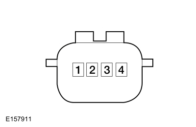 C4332, pin 1, component side
The Fuel Filler Door Lock Is Inoperative (If Equipped)
Refer to Wiring Diagrams Cell 117 for schematic and connector information.
Normal Operations and Fault Conditions
REFER to: Handles, Locks, Latches and Entry Systems - System
Operation and Component Description (501-14 Handles, Locks, Latches and
Entry Systems, Description and Operation).
Possible Causes
- Wiring, terminals or connectors
- Fuel filler door lock
- BCM
PINPOINT TEST W: THE FUEL FILLER DOOR LOCK IS INOPERATIVE (IF EQUIPPED)
| NOTICE: Use the correct probe adapter(s) when making measurements. Failure to use the correct probe adapter(s) may damage the connector. | ||||||||||
| W1 CHECK THE DRIVER DOOR LOCK OPERATION | ||||||||||
Does the driver door lock operate correctly?
|
||||||||||
| W2 CHECK THE FUEL FILLER DOOR LOCK CIRCUIT FOR AN OPEN | ||||||||||
|
NOTICE: The following step uses a test lamp to simulate normal circuit loads. Use only a Rotunda Test Lamp (SGT27000) or 250-300mA incandescent bulb test lamp. To avoid connector terminal damage, use the Rotunda Flex Probe kit for the test lamp probe connection to the vehicle. Do not use the test lamp probe directly on any connector.
Does the test lamp momentarily illuminate?
|
||||||||||
| W3 CHECK THE FUEL FILLER DOOR UNLOCK CIRCUIT FOR AN OPEN | ||||||||||
|
NOTICE: The following step uses a test lamp to simulate normal circuit loads. Use only a Rotunda Test Lamp (SGT27000) or 250-300mA incandescent bulb test lamp. To avoid connector terminal damage, use the Rotunda Flex Probe kit for the test lamp probe connection to the vehicle. Do not use the test lamp probe directly on any connector.
Does the test lamp momentarily illuminate?
|
The Approach Detection Feature Is Inoperative
Normal Operations and Fault Conditions
REFER to: Handles, Locks, Latches and Entry Systems - System
Operation and Component Description (501-14 Handles, Locks, Latches and
Entry Systems, Description and Operation).
BCM DTC Fault Trigger Conditions
| DTC | Description | Fault Trigger Conditions |
|---|---|---|
| B10C6:01 | Exterior Trunk Antenna: General Electrical Failure | Set by the BCM when a fault is detected on the approach detection antenna or circuits. |
Possible Cause
- Approach detection disabled
- A programmed key is inside the vehicle
- Passive entry system concern
- Illuminated entry concern
- RKE system concern
Visual Inspection and Diagnostic Pre-checks
- Remove any vehicle specific keys from the vehicle interior.
PINPOINT TEST X: THE APPROACH DETECTION FEATURE IS INOPERATIVE
| X1 CHECK THE APPROACH DETECTION SETTING | |||||||||||||
Is the approach detection setting enabled?
|
|||||||||||||
| X2 CHECK THE PASSIVE ENTRY FEATURE | |||||||||||||
Does the passive entry feature operate from the front doors and the liftgate?
|
|||||||||||||
| X3 CHECK THE ILLUMINATED ENTRY OPERATION | |||||||||||||
Does the illuminated entry feature operate correctly?
|
|||||||||||||
| X4 CHECK THE APPROACH DETECTION ANTENNA CIRCUITS FOR A SHORT TO VOLTAGE | |||||||||||||
Is any voltage present?
|
|||||||||||||
| X5 CHECK THE APPROACH DETECTION ANTENNA CIRCUITS FOR A SHORT TO GROUND | |||||||||||||
Are the resistances greater than 10,000 ohms?
|
|||||||||||||
| X6 CHECK THE APPROACH DETECTION ANTENNA CIRCUITS FOR AN OPEN | |||||||||||||
Are the resistances less than 3 ohms?
|
|||||||||||||
| X7 CHECK THE APPROACH DETECTION ANTENNA CIRCUITS FOR A SHORT TOGETHER | |||||||||||||
Is the resistance greater than 10,000 ohms?
|
|||||||||||||
| X8 CHECK THE APPROACH DETECTION ANTENNA | |||||||||||||
Is the resistance between 1 and 10 ohms?
|
|||||||||||||
| X9 CHECK FOR CORRECT BCM (BODY CONTROL MODULE) OPERATION | |||||||||||||
Is the concern still present?
|
The RKE Exterior Sounder Continuously Chimes
Refer to Wiring Diagrams Cell 117 for schematic and connector information.
Normal Operations and Fault Conditions
REFER to: Handles, Locks, Latches and Entry Systems - System
Operation and Component Description (501-14 Handles, Locks, Latches and
Entry Systems, Description and Operation).
BCM DTC Fault Trigger Conditions
| DTC | Description | Fault Trigger Conditions |
|---|---|---|
| B14B8:15 | Sounder: Circuit Short To Battery or Open | Sets when the BCM detects a short to voltage from the RKE exterior sounder voltage supply circuit. |
Possible Cause
- Wiring, terminals or connectors
- BCM
PINPOINT TEST Y: THE RKE (REMOTE KEYLESS ENTRY) EXTERIOR SOUNDER CONTINUOUSLY CHIMES
| Y1 CHECK THE RKE (REMOTE KEYLESS ENTRY) EXTERIOR SOUNDER VOLTAGE SUPPLY CIRCUIT FOR A SHORT TO VOLTAGE | ||||
Does the RKE exterior sounder continue to chime?
|
||||
| Y2 CHECK FOR CORRECT BCM (BODY CONTROL MODULE) OPERATION | ||||
Is the concern still present?
|
The RKE Exterior Sounder Is Inoperative
Refer to Wiring Diagrams Cell 117 for schematic and connector information.
Normal Operations and Fault Conditions
REFER to: Handles, Locks, Latches and Entry Systems - System
Operation and Component Description (501-14 Handles, Locks, Latches and
Entry Systems, Description and Operation).
BCM DTC Fault Trigger Conditions
| DTC | Description | Fault Trigger Conditions |
|---|---|---|
| B14B8:11 | Sounder: Circuit Short To Ground | Sets when the BCM detects a short to ground from the RKE exterior sounder voltage supply circuit. |
| B14B8:15 | Sounder: Circuit Short To Battery or Open | Sets when the BCM detects an open from the RKE exterior sounder voltage supply circuit. |
Possible Cause
- Wiring, terminals or connectors
- RKE exterior sounder
- BCM
PINPOINT TEST Z: THE RKE (REMOTE KEYLESS ENTRY) EXTERIOR SOUNDER IS INOPERATIVE
| Z1 CHECK THE BCM (BODY CONTROL MODULE) EXTERIOR SOUNDER OUTPUT | ||||||||||
|
NOTICE: The following step uses a test lamp to simulate normal circuit loads. Use only a Rotunda Test Lamp (SGT27000) or 250-300mA incandescent bulb test lamp. To avoid connector terminal damage, use the Rotunda Flex Probe kit for the test lamp probe connection to the vehicle. Do not use the test lamp probe directly on any connector.
Does the test lamp momentarily illuminate?
|
||||||||||
| Z2 CHECK THE RKE (REMOTE KEYLESS ENTRY) EXTERIOR SOUNDER GROUND CIRCUIT FOR AN OPEN | ||||||||||
|
NOTICE: The following step uses a test lamp to simulate normal circuit loads. Use only a Rotunda Test Lamp (SGT27000) or 250-300mA incandescent bulb test lamp. To avoid connector terminal damage, use the Rotunda Flex Probe kit for the test lamp probe connection to the vehicle. Do not use the test lamp probe directly on any connector.
Does the test lamp momentarily illuminate?
|
||||||||||
| Z3 CHECK THE RKE (REMOTE KEYLESS ENTRY) EXTERIOR SOUNDER VOLTAGE SUPPLY CIRCUIT FOR A SHORT TO GROUND | ||||||||||
Is the resistance greater than 10,000 ohms?
|
||||||||||
| Z4 CHECK THE RKE (REMOTE KEYLESS ENTRY) EXTERIOR SOUNDER VOLTAGE SUPPLY CIRCUIT FOR AN OPEN | ||||||||||
Is the resistance less than 3 ohms?
|
||||||||||
| Z5 CHECK FOR CORRECT BCM (BODY CONTROL MODULE) OPERATION | ||||||||||
Is the concern still present?
|
P1594 OR P1595
Normal Operation and Fault Conditions
When the BCM receives a request to remote start the vehicle, it first checks to make sure conditions exist to allow it to start (for example, the hood and doors closed, vehicle in PARK, no powertrain concerns). If the required conditions are correct, the BCM starts the vehicle and allows it to run for a predetermined amount of time, determined by the setting selected from the message center.
PCM DTC Fault Trigger Conditions
| DTC | Description | Fault Trigger Conditions |
|---|---|---|
| P1594 | Forced Engine Shutdown - Remote Start System Fault, No Unattended Vehicle Timeout | Sets when the PCM detects the remote start has been active for more than 30 minutes continuously. |
| P1595 | Forced Engine Shutdown - Remote Start System Fault, Transmission Range Not In Park Position | Sets when the PCM detects the remote start is active with the transmission not in PARK. |
Possible Causes
- Network communication concern
- Powertrain concern
- BCM
PINPOINT TEST AA: P1594 OR P1595
| AA1 CHECK FOR OTHER PCM (POWERTRAIN CONTROL MODULE) DIAGNOSTIC TROUBLE CODES (DTCS) | ||||
Are any other PCM Diagnostic Trouble Codes (DTCs) present?
|
||||
| AA2 CHECK FOR BCM (BODY CONTROL MODULE) DIAGNOSTIC TROUBLE CODES (DTCS) | ||||
Are any BCM Diagnostic Trouble Codes (DTCs) present?
|
||||
| AA3 CHECK FOR CORRECT BCM (BODY CONTROL MODULE) OPERATION | ||||
Is the concern still present?
|
U0140:00
Normal Operation and Fault Conditions
The DDM and PDM communicate with the BCM over the CAN . If the DDM or PDM do not receive messages from the BCM , features such as the puddle lamps, exterior mirror turn signal, and door switch illumination can be inoperative.
DDM / PDM DTC Fault Trigger Conditions
| DTC | Description | Fault Trigger Conditions |
|---|---|---|
| U0140:00 | Lost Communication With Body Control Module: No Sub-Type Information | Set by the DDM and PDM when data messages are missing from the BCM . |
Possible Causes
- Network communication concern
- DDM
- PDM
- BCM
PINPOINT TEST AB: U0140:00
| AB1 VERIFY THE CUSTOMER CONCERN | ||||
Is an observable symptom present?
|
||||
| AB2 CHECK THE COMMUNICATION NETWORK | ||||
Does the BCM pass the network test?
|
||||
| AB3 CHECK FOR BCM (BODY CONTROL MODULE) DIAGNOSTIC TROUBLE CODES (DTCS) | ||||
Are any voltage related Diagnostic Trouble Codes (DTCs) present?
|
||||
| AB4 RECHECK THE DDM (DRIVER DOOR MODULE) OR PDM (PASSENGER DOOR MODULE) DIAGNOSTIC TROUBLE CODES (DTCS) | ||||
|
NOTE: If new modules were installed prior to the DTC being set, the module configuration may be incorrectly set during PMI or the PMI may not have been carried out.
Is DTC U0140:00 still present?
|
||||
| AB5 CHECK FOR DTC (DIAGNOSTIC TROUBLE CODE) U0140:00 SET IN OTHER MODULES | ||||
Is DTC U0140:00 set in other modules?
|
U0146:00
Normal Operations and Fault Conditions
The RTM communicates with the GWM over the CAN . If the RTM does not receive messages from the GWM , features such as the passive entry can be inoperative.
RTM DTC Fault Trigger Conditions
| DTC | Description | Fault Trigger Conditions |
|---|---|---|
| U0146:00 | Lost Communication With Gateway "A": No Sub Type Information | Sets when the RTM detects data messages are missing from the GWM over the CAN . |
Possible Causes
- Network communication concern
- GWM
PINPOINT TEST AC: U0146:00
| AC1 VERIFY THE CUSTOMER CONCERN | ||||
Is an observable symptom present?
|
||||
| AC2 CHECK THE COMMUNICATION NETWORK | ||||
Does the GWM pass the network test?
|
||||
| AC3 CHECK FOR NON-NETWORK GWM (GATEWAY MODULE A) DIAGNOSTIC TROUBLE CODES (DTCS) | ||||
Are any non-network Diagnostic Trouble Codes (DTCs) present?
|
||||
| AC4 CHECK FOR NON-NETWORK RTM (RADIO TRANSCEIVER MODULE) DIAGNOSTIC TROUBLE CODES (DTCS) | ||||
Are any non-network Diagnostic Trouble Codes (DTCs) present?
|
||||
| AC5 RECHECK THE RTM (RADIO TRANSCEIVER MODULE) DIAGNOSTIC TROUBLE CODES (DTCS) | ||||
Is DTC U0146:00 still present?
|
||||
| AC6 CHECK FOR OTHER CAUSES OF COMMUNICATION NETWORK CONCERN | ||||
|
NOTE: If new modules were installed prior to the DTC being set, the module configuration may be incorrectly set during PMI or the PMI may not have been carried out.
Is the observable symptom still present?
|
||||
| AC7 CHECK FOR CORRECT GWM (GATEWAY MODULE A) OPERATION | ||||
Is the concern still present?
|
U0232:00
Normal Operation and Fault Conditions
The DDM communicates with the SODL over the CAN . If the DDM does not receive messages from the SODL , the side obstacle detection feature can be inoperative for the left side.
DDM DTC Fault Trigger Conditions
| DTC | Description | Fault Trigger Conditions |
|---|---|---|
| U0232:00 | Lost Communication With Side Obstacle Detection Control Module - Left: No Sub-Type Information | Sets when the DDM detects data messages are missing from the SODL . |
Possible Causes
- Network communication concern
- SODL
PINPOINT TEST AD: U0232:00
| AD1 VERIFY THE CUSTOMER CONCERN | ||||
Is an observable symptom present?
|
||||
| AD2 CHECK THE COMMUNICATION NETWORK | ||||
Does the SODL pass the network test?
|
||||
| AD3 CHECK FOR NON-NETWORK SODL (SIDE OBSTACLE DETECTION CONTROL MODULE LH) DIAGNOSTIC TROUBLE CODES (DTCS) | ||||
Are any non-network Diagnostic Trouble Codes (DTCs) present?
|
||||
| AD4 CHECK FOR NON-NETWORK DDM (DRIVER DOOR MODULE) DIAGNOSTIC TROUBLE CODES (DTCS) | ||||
Are any non-network Diagnostic Trouble Codes (DTCs) present?
|
||||
| AD5 RECHECK THE DDM (DRIVER DOOR MODULE) DIAGNOSTIC TROUBLE CODES (DTCS) | ||||
Is DTC U0232:00 still present?
|
||||
| AD6 CHECK FOR OTHER CAUSES OF COMMUNICATION NETWORK CONCERN | ||||
|
NOTE: If new modules were installed prior to the DTC being set, the module configuration may be incorrectly set during PMI or the PMI may not have been carried out.
Is the observable symptom still present?
|
||||
| AD7 CHECK FOR CORRECT SODL (SIDE OBSTACLE DETECTION CONTROL MODULE LH) OPERATION | ||||
Is the concern still present?
|
U0233:00
Normal Operation and Fault Conditions
The PDM communicates with the SODR over the CAN . If the PDM does not receive messages from the SODR , the side obstacle detection feature can be inoperative for the right side.
PDM DTC Fault Trigger Conditions
| DTC | Description | Fault Trigger Conditions |
|---|---|---|
| U0233:00 | Lost Communication With Side Obstacle Detection Control Module - Right: No Sub-Type Information | Sets when the PDM detects data messages are missing from the SODR . |
Possible Causes
- Network communication concern
- SODR
PINPOINT TEST AE: U0233:00
| AE1 VERIFY THE CUSTOMER CONCERN | ||||
Is an observable symptom present?
|
||||
| AE2 CHECK THE COMMUNICATION NETWORK | ||||
Does the SODR pass the network test?
|
||||
| AE3 CHECK FOR NON-NETWORK SODR (SIDE OBSTACLE DETECTION CONTROL MODULE RH) DIAGNOSTIC TROUBLE CODES (DTCS) | ||||
Are any non-network Diagnostic Trouble Codes (DTCs) present?
|
||||
| AE4 CHECK FOR NON-NETWORK PDM (PASSENGER DOOR MODULE) DIAGNOSTIC TROUBLE CODES (DTCS) | ||||
Are any non-network Diagnostic Trouble Codes (DTCs) present?
|
||||
| AE5 RECHECK THE PDM (PASSENGER DOOR MODULE) DIAGNOSTIC TROUBLE CODES (DTCS) | ||||
Is DTC U0233:00 still present?
|
||||
| AE6 CHECK FOR OTHER CAUSES OF COMMUNICATION NETWORK CONCERN | ||||
|
NOTE: If new modules were installed prior to the DTC being set, the module configuration may be incorrectly set during PMI or the PMI may not have been carried out.
Is the observable symptom still present?
|
||||
| AE7 CHECK FOR CORRECT SODR (SIDE OBSTACLE DETECTION CONTROL MODULE RH) OPERATION | ||||
Is the concern still present?
|
U0258:87 or U1A00:00
Refer to Wiring Diagrams Cell 117 for schematic and connector information.
Normal Operation and Fault Conditions
The RTM communicates with the BCM over a LIN -based circuit and, when the network is awake, over the CAN .
BCM DTC Fault Trigger Conditions
| DTC | Description | Fault Trigger Conditions |
|---|---|---|
| U0258:87 | Lost Communication With Radio Transceiver: Missing Message | Sets when the BCM detects a communication fault with the RTM over the LIN -based circuit. |
RTM DTC Fault Trigger Conditions
| DTC | Description | Fault Trigger Conditions |
|---|---|---|
| U1A00:00 | Private Communication Network: No Sub Type Information | Sets when the RTM detects a fault with the LIN -based circuit to the BCM . |
Possible Causes
- Wiring, terminals or connectors
- RTM
- BCM
PINPOINT TEST AF: U0258:87 OR U1A00:00
| AF1 CHECK IF THE RTM (RADIO TRANSCEIVER MODULE) AND THE BCM (BODY CONTROL MODULE) PASS THE NETWORK TEST | ||||||||||
Does the RTM and the BCM pass the network test?
|
||||||||||
| AF2 CHECK THE LIN (LOCAL INTERCONNECT NETWORK) CIRCUIT FOR A SHORT TO VOLTAGE | ||||||||||
|
NOTE: It is necessary to place the passive key in the backup starting location to transition the ignition on. To identify the backup starting location, refer to and “backup slot” in the Owner's Literature.
Is any voltage present?
|
||||||||||
| AF3 CHECK THE LIN (LOCAL INTERCONNECT NETWORK) CIRCUIT FOR A SHORT TO GROUND | ||||||||||
Is the resistance greater than 10,000 ohms?
|
||||||||||
| AF4 CHECK THE LIN (LOCAL INTERCONNECT NETWORK) CIRCUIT FOR AN OPEN | ||||||||||
Is the resistance less than 3 ohms?
|
||||||||||
| AF5 CHECK FOR CORRECT RTM (RADIO TRANSCEIVER MODULE) OPERATION | ||||||||||
Is the concern still present?
|
||||||||||
| AF6 CHECK FOR CORRECT BCM (BODY CONTROL MODULE) OPERATION | ||||||||||
Is the concern still present?
|
|
Refer to Wiring Diagrams Cell 109 for schematic and connector information. Normal Operation and Fault Conditions
REFER to: Handles, Locks, Latches and Entry Systems - System Operation
and Component Description (501-14 Handles, Locks, Latches and Entry
Systems, Description and Operation). DTC Fault Trigger Conditions
Possible Sources
|
|||||||||||||||
| AG1 RECHECK FOR DIAGNOSTIC TROUBLE CODES (DTCS) | |||||||||||||||
Is BCM DTC B1584:11, B1584:12, or B1584:13 set in the BCM ?
|
|||||||||||||||
| AG2 CHECK THE CIRCUIT TO THE LIFTGATE WINDOW GLASS RELEASE SWITCH FOR A SHORT TO VOLTAGE | |||||||||||||||
Is any voltage present?
|
|||||||||||||||
| AG3 CHECK THE CIRCUIT TO THE LIFTGATE WINDOW GLASS RELEASE SWITCH FOR A SHORT TO GROUND | |||||||||||||||
Is the resistances greater than 10,000 ohms?
|
|||||||||||||||
| AG4 CHECK THE CIRCUIT TO THE LIFTGATE WINDOW GLASS RELEASE SWITCH CIRCUIT FOR AN OPEN | |||||||||||||||
Are the resistances less than 3 ohms?
|
|||||||||||||||
| AG5 BYPASS THE LIFTGATE WINDOW GLASS RELEASE SWITCH | |||||||||||||||
Did the liftgate window latch release?
|
|||||||||||||||
| AG6 CHECK THE BCM (BODY CONTROL MODULE) LIFTGATE WINDOW LATCH CIRCUIT FOR A SHORT TO VOLTAGE | |||||||||||||||
Is any voltage present?
|
|||||||||||||||
| AG7 CHECK THE BCM (BODY CONTROL MODULE) LIFTGATE WINDOW LATCH CIRCUIT FOR A SHORT TO GROUND | |||||||||||||||
Is the resistance greater than 10,000 ohms?
|
|||||||||||||||
| AG8 CHECK THE BCM (BODY CONTROL MODULE) LIFTGATE WINDOW LATCH CIRCUIT FOR AN OPEN | |||||||||||||||
Is the resistance less than 3 ohms?
|
|||||||||||||||
| AG9 CHECK FOR VOLTAGE TO THE LIFTGATE WINDOW LATCH | |||||||||||||||
|
NOTE: The Body Control Module (BCM) only supplies voltage to the latch momentarily. It is important to monitor the test lamp while pressing the liftgate window glass release switch. Observe the test lamp while pressing the liftgate window glass release switch.
Does the test lamp momentarily illuminate?
|
|||||||||||||||
| AG10 CHECK FOR CORRECT OPERATION | |||||||||||||||
Is the concern still present?
|
|||||||||||||||
| AG11 CHECK FOR CORRECT BCM (BODY CONTROL MODULE) OPERATION | |||||||||||||||
Is the concern still present?
|
|
Refer to Wiring Diagrams Cell 117 for schematic and connector information. Normal Operation and Fault Conditions
REFER to: Handles, Locks, Latches and Entry Systems - System Operation
and Component Description (501-14 Handles, Locks, Latches and Entry
Systems, Description and Operation). DTC Fault Trigger Conditions
Possible Sources
Visual Inspection and Pre-checks
NOTE: Low vehicle battery state of charge will disable the passive entry feature from all the doors except the driver’s door. |
||||||||||||||||
| AH1 RECHECK FOR DTC (DIAGNOSTIC TROUBLE CODE) U3003:16 | ||||||||||||||||
Is DTC U3003:16 still present?
|
||||||||||||||||
| AH2 CHECK FOR CHARGING SYSTEM DIAGNOSTIC TROUBLE CODES (DTCS) IN THE PCM (POWERTRAIN CONTROL MODULE) | ||||||||||||||||
Are any voltage-related Diagnostic Trouble Codes (DTCs) set in the PCM ?
|
||||||||||||||||
| AH3 CHECK THE BATTERY CONDITION AND STATE OF CHARGE | ||||||||||||||||
Is the battery OK and fully charged?
|
||||||||||||||||
| AH4 CHECK THE SUSPECT MODULE VOLTAGE SUPPLY | ||||||||||||||||
Is the voltage within 0.2 volts of the recorded battery voltage?
|
||||||||||||||||
| AH5 CHECK THE SUSPECT MODULE GROUND CIRCUIT | ||||||||||||||||
Is the DDM / PDM voltage greater than 11 volts?
|
||||||||||||||||
| AH6 CHECK THE SUSPECT MODULE FOR AN OPEN CIRCUIT | ||||||||||||||||
Is the resistance less than 3 ohms?
|
||||||||||||||||
| AH7 CHECK FOR CORRECT DDM (DRIVER DOOR MODULE) OPERATION | ||||||||||||||||
Is the concern still present?
|
||||||||||||||||
| AH8 CHECK FOR CORRECT PDM (PASSENGER DOOR MODULE) OPERATION | ||||||||||||||||
Is the concern still present?
|
|
Refer to Wiring Diagrams Cell 117 for schematic and connector information. Normal Operation and Fault Conditions
REFER to: Handles, Locks, Latches and Entry Systems - System Operation
and Component Description (501-14 Handles, Locks, Latches and Entry
Systems, Description and Operation). DTC Fault Trigger Conditions
Possible Sources
|
|||||||||
| AI1 RECHECK FOR DTC (DIAGNOSTIC TROUBLE CODE) U3003:17 | |||||||||
Is DTC U3003:17 present?
|
|||||||||
| AI2 CHECK FOR HIGH VOLTAGE DIAGNOSTIC TROUBLE CODES (DTCS) SET IN MULTIPLE MODULES | |||||||||
Are high voltage Diagnostic Trouble Codes (DTCs) such as B1676, P0563, or U3003:17 set in more than one module?
|
|||||||||
| AI3 CHECK THE BATTERY VOLTAGE | |||||||||
Does the battery voltage rise to 15.5 volts or higher?
|
|||||||||
| AI4 CHECK FOR CORRECT DDM (DRIVER DOOR MODULE) OPERATION | |||||||||
Is the concern still present?
|
|||||||||
| AI5 CHECK FOR CORRECT PDM (PASSENGER DOOR MODULE) OPERATION | |||||||||
Is the concern still present?
|

 Door Latch Lubrication. General Procedures
Special Tool(s) /
General Equipment
Flat-Bladed Screwdriver
Materials
Name
Specification
Motorcraft® Multi-Purpose Grease SprayXL-5-A
ESB-M1C93-B
Activation
NOTE:
Typical left front door shown, others similar...
Other information:
Lincoln Navigator 2018-2026 Workshop Manual: Roof Opening Panel - System Operation and Component Description. Description and Operation
System Operation Item Description 1 BCM 2 Sliding Glass Motor 3 Roof Opening Panel Control Switch 4 Shield Motor 5 K Bus (not used for external communication) Switch Operation There are three switches located in the overhead console...
Lincoln Navigator 2018-2026 Workshop Manual: Remote Function Actuator (RFA) Module. Removal and Installation
Removal NOTE: This step is only necessary when installing a new component. NOTE: If installing a new module, it is necessary to upload the module configuration information to the diagnostic scan tool prior to removing the module...
Categories
- Manuals Home
- 4th Gen Lincoln Navigator Service Manual (2018 - 2026)
- Transmission Fluid Level Check. General Procedures
- Identification Codes. Description and Operation
- Transmission Fluid Drain and Refill. General Procedures
- Windshield Washer Pump. Removal and Installation
- All Terrain Control Module (ATCM). Removal and Installation
Rear Drive Halfshafts. Diagnosis and Testing
Preliminary Inspection
Visually inspect the CV joints, housing, boots, and clamps for obvious signs of mechanical damage.If an obvious cause for an observed or reported concern is found, correct the cause (if possible) before proceeding to the next step
If the cause is not visually evident, verify the symptom and REFER to Symptom Chart: NVH.