Lincoln Navigator: Engine Emission Control - 3.5L EcoBoost (272kW/370PS) / Engine Emission Control - Component Location. Description and Operation
| Item | Description |
|---|---|
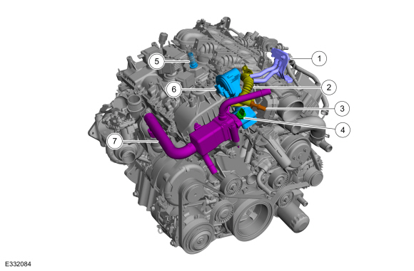
| 1 | Differential pressure feedback EGR sensor. |
| 2 | EGR outlet tube. |
| 3 | EGR temperature sensor. |
| 4 | EGR back pressure sensor. |
| 5 | PCV valve. |
| 6 | EGR valve. |
| 7 | EGR cooler. |

 Engine Emission Control - System Operation and Component Description. Description and Operation
System Operation
Exhaust Gas Recirculation (EGR) System
Overview
The EGR system controls the NOX
emissions. Small amounts of exhaust gases are recirculated back into
the combustion chamber to mix with the air to fuel charge...
Other information:
Lincoln Navigator 2018-2026 Workshop Manual: Head Up Display (HUD) Module. Removal and Installation
Removal NOTE: Removal steps in this procedure may contain installation details. Remove the instrument panel. Refer to: Instrument Panel (501-12 Instrument Panel and Console, Removal and Installation). Disconnect the electrical connector, remove the bolts and the HUD module...
Lincoln Navigator 2018-2026 Workshop Manual: Second Row Center Seatbelt Retractor. Removal and Installation
Removal NOTE: Removal steps in this procedure may contain installation details. Remove the second row center seat backrest cover. Refer to: Second Row Center Seat Backrest Cover (501-10B Second Row Seats, Removal and Installation)...
Categories
- Manuals Home
- 4th Gen Lincoln Navigator Service Manual (2018 - 2026)
- Rear Bumper. Removal and Installation
- Head Up Display (HUD) Module Calibration. General Procedures
- Body and Paint
- Neutral Flat Tow Activation and Deactivation. General Procedures
- Front Seat. Removal and Installation
Rear Drive Halfshafts. Diagnosis and Testing
Preliminary Inspection
Visually inspect the CV joints, housing, boots, and clamps for obvious signs of mechanical damage.If an obvious cause for an observed or reported concern is found, correct the cause (if possible) before proceeding to the next step
If the cause is not visually evident, verify the symptom and REFER to Symptom Chart: NVH.