Lincoln Navigator: Electronic Engine Controls - 3.5L EcoBoost (272kW/370PS) / Catalyst Monitor Sensor. Removal and Installation
Special Tool(s) / General Equipment
 |
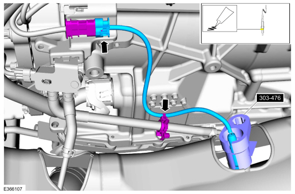
303-476
(T94P-9472-A)
Socket, Exhaust Gas Oxygen Sensor TKIT-1994-LM/M TKIT-1994-F TKIT-1994-FLM/FM |
Materials
| Name | Specification |
|---|---|
| Motorcraft® High Temperature Nickel Anti-Seize Lubricant XL-2 |
- |
| Motorcraft® Penetrating and Lock Lubricant XL-1 |
- |
Removal
All sensors
-
With the vehicle in NEUTRAL, position it on a hoist.
Refer to: Jacking and Lifting (100-02 Jacking and Lifting, Description and Operation).
-
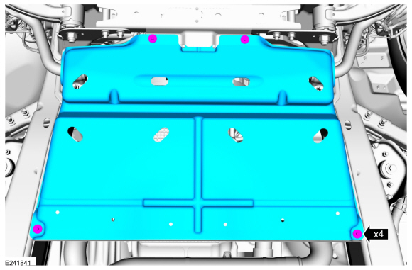
If equipped, remove the underbody shield.
 |
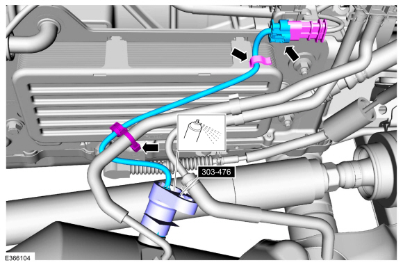
Right hand (RH) Catalyst monitor sensor
-
-
Disconnect the electrical connector.
-
Apply penetrating oil to sensor, using the special tool remove the Catalyst monitor sensor.
Use Special Service Tool: 303-476 (T94P-9472-A) Socket, Exhaust Gas Oxygen Sensor.
Material: Motorcraft® Penetrating and Lock Lubricant / XL-1
-
Disconnect the electrical connector.
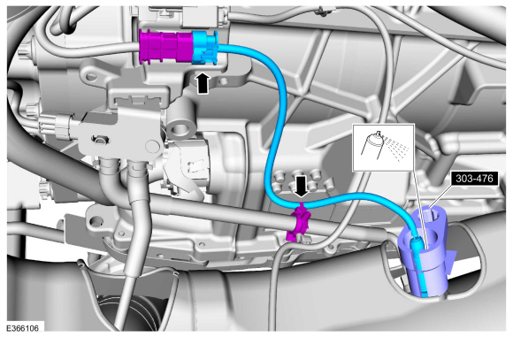 |
Left hand (LH) Catalyst monitor sensor
-
Disconnect the electrical connector and harness
retainers. Apply penetrating oil to sensor, using the special tool
remove the Catalyst monitor sensor.
Use Special Service Tool: 303-476 (T94P-9472-A) Socket, Exhaust Gas Oxygen Sensor.
Material: Motorcraft® Penetrating and Lock Lubricant / XL-1
 |
Installation
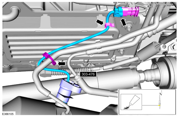
Left hand (LH) Catalyst monitor sensor
-
-
Apply anti-seize to thread of sensor, using special tool install the Catalyst monitor sensor.
Use Special Service Tool: 303-476 (T94P-9472-A) Socket, Exhaust Gas Oxygen Sensor.
Material: Motorcraft® High Temperature Nickel Anti-Seize Lubricant / XL-2
Torque: 35 lb.ft (48 Nm)
-
Connect the electrical connector and harness retainers.
-
Apply anti-seize to thread of sensor, using special tool install the Catalyst monitor sensor.
 |
Right hand (RH) Catalyst monitor sensor
-
-
Apply anti-seize to thread of sensor, using special tool install the Catalyst monitor sensor.
Use Special Service Tool: 303-476 (T94P-9472-A) Socket, Exhaust Gas Oxygen Sensor.
Material: Motorcraft® High Temperature Nickel Anti-Seize Lubricant / XL-2
Torque: 35 lb.ft (48 Nm)
-
Connect the electrical connector and harness retainers.
-
Apply anti-seize to thread of sensor, using special tool install the Catalyst monitor sensor.
 |
All sensors
-
If equipped, install the underbody shield.
Torque: 71 lb.in (8 Nm)
|
 Camshaft Position (CMP) Sensor. Removal and Installation
Materials
Name
Specification
Engine Oil - SAE 5W-30 - Synthetic Blend Motor OilXO-5W30-Q1SP
WSS-M2C946-B1
Removal
NOTE:
Removal steps in this procedure may contain installation details...
 Crankshaft Position (CKP) Sensor. Removal and Installation
Removal
NOTE:
Removal steps in this procedure may contain installation details.
Remove the LH turbocharger.
Refer to: Turbocharger LH (303-04B Fuel Charging and Controls -
Turbocharger - 3...
Other information:
Lincoln Navigator 2018-2026 Workshop Manual: Tire Pressure Monitoring System (TPMS) - Component Location. Description and Operation
Item Description 1 RTM 2 BCM 3 TPMS sensor assembly (4 required) ..
Lincoln Navigator 2018-2026 Workshop Manual: Specifications
Engine Item Specification Displacement 3.5L Ecoboost (214 CID) No. of cylinders 6 Bore/stroke 92.5/86.7 mm (3.641/3.413 in) Firing order 1-4-2-5-3-6 Spark plug 12405 Spark plug gap 0.75 mm C..
Categories
- Manuals Home
- 4th Gen Lincoln Navigator Service Manual (2018 - 2026)
- Vehicle Dynamics Control Module (VDM). Removal and Installation
- SYNC Module [APIM]. Removal and Installation
- Front Bumper Cover. Removal and Installation
- Remote Function Actuator (RFA) Module. Removal and Installation
- Liftgate Trim Panel. Removal and Installation
Differential Case Runout Check. General Procedures
Special Tool(s) / General Equipment
 205-1016
Installer, Differential Bearing
TKIT-2014D-ROW2
TKIT-2014D-FL_ROW
 205-153
(T80T-4000-W)
205-153
(T80T-4000-W)
Handle
 205-D061
(D83T-4205-C2)
205-D061
(D83T-4205-C2)
Step Plate Dial Indicator Three Leg Puller Punch