Lincoln Navigator: Bumpers / Rear Bumper Cover. Removal and Installation
Special Tool(s) / General Equipment
| Interior Trim Remover |
Removal
NOTE: Removal steps in this procedure may contain installation details.
-
With the vehicle in NEUTRAL, position it on a hoist.
Refer to: Jacking and Lifting (100-02 Jacking and Lifting, Description and Operation).
-
On both sides.
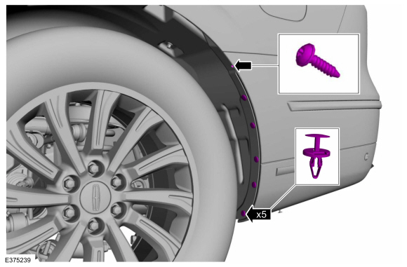
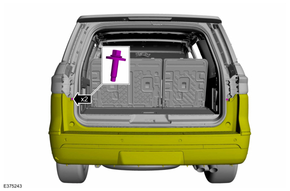
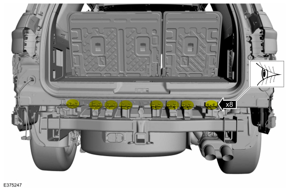
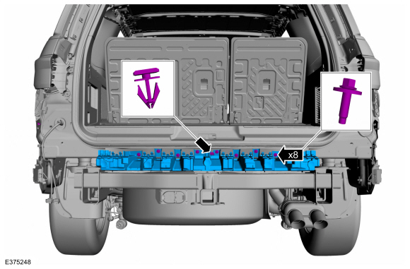
Remove the push pins and the screw.
Torque: 21 lb.in (2.4 Nm)
 |
-
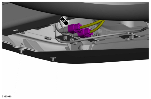
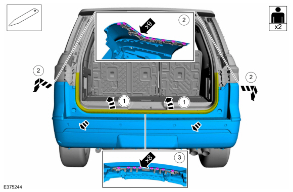
Disconnect the rear bumper cover electrical connectors.
 |
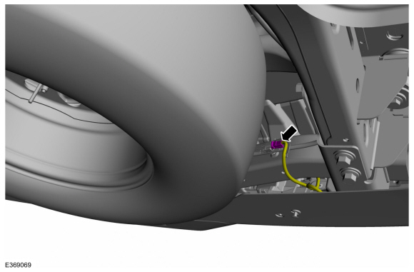
Vehicles With: Hands-Free Liftgate
-
Disconnect the rear bumper cover electrical connector.
 |
All vehicles
-
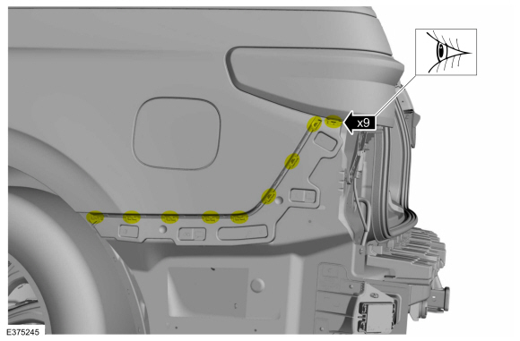
On both sides.
Release the clips and remove the rear lamp cover assembly.
 |
-
Remove the screws.
Torque: 53 lb.in (6 Nm)
 |
-
NOTE: This step requires the aid of another technician.
Remove the rear bumper cover.
-
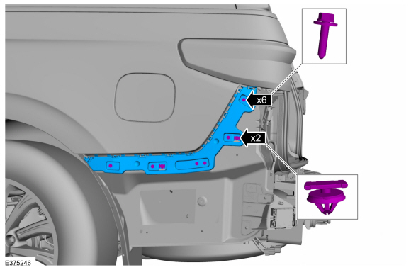
Position the luggage compartment weatherstrip aside.
-
Release the sides of the rear bumper cover from the side brackets.
-
Using a non-marring tool, release the center of the rear bumper cover from the rear bracket.
Use the General Equipment: Interior Trim Remover
-
Position the luggage compartment weatherstrip aside.
 |
-
On both sides.
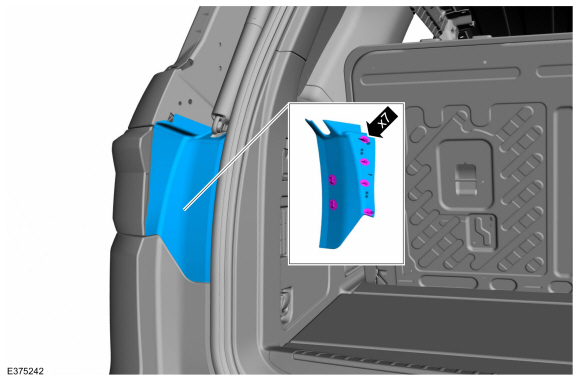
Inspect the side bracket for damage.
 |
-
If required, on both sides.
Remove the screws, the trim-pins and the damaged side bracket.
Torque: 13 lb.in (1.5 Nm)
 |
-
Inspect the rear bracket for damage.
 |
-
If required.
Remove the screws, the trim-pin and the rear bracket.
Torque: 53 lb.in (6 Nm)
 |
Installation
-
To install, reverse the removal procedure.
Vehicles With: Rear Parking Aid
-
If replacing the rear bumper cover.
Check the alignment of the rear parking aid sensors.
Refer to: Azimuth System Check (413-13A Parking Aid, General Procedures).
Refer to: Elevation System Check (413-13A Parking Aid, General Procedures).
-
If any sensor fails the check, diagnose the sensor fault.
Refer to: Parking Aid (413-13A Parking Aid, Diagnosis and Testing).
Vehicles With: Active Park Assist
-
If replacing the rear bumper cover.
Check the alignment of the rear active park assist sensors.
Refer to: Azimuth System Check (413-13C Parking Aid - Vehicles With: Active Park Assist, General Procedures).
-
If any sensor fails the check, diagnose the sensor fault.
Refer to: Parking Aid (413-13C Parking Aid - Vehicles With: Active Park Assist, Diagnosis and Testing).
 Rear Bumper. Removal and Installation
Removal
NOTE:
Removal steps in this procedure may contain installation details.
Remove the rear bumper cover.
Refer to: Rear Bumper Cover (501-19 Bumpers, Removal and Installation)...
 Front Bumper Cover. Disassembly and Assembly
Special Tool(s) /
General Equipment
Electric Drill
DISASSEMBLY
NOTE:
Disassembly steps in this procedure may contain assembly details...
Other information:
Lincoln Navigator 2018-2026 Workshop Manual: Image Processing Module A (IPMA). Removal and Installation
Removal If a new IPMA is being installed, using a diagnostic scan tool, begin the PMI process for the IPMA following the on-screen instructions. Disconnect the trailer tow lighting module electrical connectors. Remove the bolts and trailer tow lighting module...
Lincoln Navigator 2018-2026 Workshop Manual: Instrument Panel and Interior Switches Illumination - System Operation and Component Description. Description and Operation
System Operation System Operation Overview - Dimmable Illumination Dimmable illumination provides backlighting to switches and control components when the parking lamps are on. The level of intensity for the dimmable backlit components is adjusted by using the instrument panel dimmer switch to increase or decrease intensity...
Categories
- Manuals Home
- 4th Gen Lincoln Navigator Service Manual (2018 - 2026)
- Head Up Display (HUD) Module Calibration. General Procedures
- Telematics Control Unit (TCU) Module. Removal and Installation
- Windshield Washer Pump. Removal and Installation
- Transmission Fluid Level Check. General Procedures
- Front Bumper Cover. Removal and Installation
Wheel to Hub Runout Minimization. General Procedures
Check
NOTE: Wheel-to-hub optimization is important. Clearance between the wheel and hub can be used to offset or neutralize the Road Force® or run-out of the wheel and tire assembly. For every 0.001 inch of wheel-to-hub clearance, the Road Force® can be affected between 1 and 3 pounds depending on the tire stiffness.
NOTE: The example below illustrates how the clearance between the wheel and the hub can be used to offset the high spot of radial run-out or Road Force®. Following the procedure will make sure of the best optimization.
Position the wheel and tire assembly on the vehicle so that the high spot location of radial run-out or Road Force® is at the 6 o'clock position and