Lincoln Navigator: Body Closures / Fuel Filler Door. Removal and Installation
Removal
-
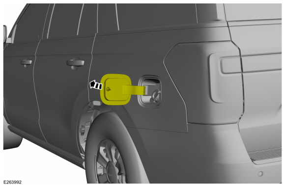
Open the fuel filler door.
 |
-
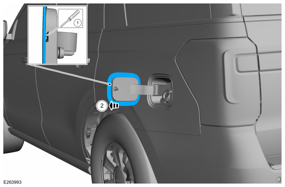
Using a screwdriver, push the retaining tab and slide the fuel filler door and remove.
 |
Installation
-
To install, reverse the removal procedure.
 Front Door Weatherstrip. Removal and Installation
Special Tool(s) /
General Equipment
Interior Trim Remover
Removal
NOTE:
Removal steps in this procedure may contain installation details...
 Fuel Filler Door Assembly. Removal and Installation
Special Tool(s) /
General Equipment
Flat Headed Screw Driver
Knife
Removal
NOTE:
Removal steps in this procedure may contain installation details...
Other information:
Lincoln Navigator 2018-2026 Workshop Manual: Second Row Seat Head Restraint Guide Sleeve. Removal and Installation
Special Tool(s) / General Equipment Flat Headed Screw Driver Removal NOTE: Typical head restraint guide sleeve shown, others similar. Depress the tabs and remove the head restraint. NOTE: Follow the unique instructions or graphic for this step in the installation...
Lincoln Navigator 2018-2026 Workshop Manual: Adaptive Learning Drive Cycle. General Procedures
Programming NOTE: Perform the adaptive learning drive cycle on a level road surface. Using the scan tool, clear the DTCs (Diagnostic Trouble Codes) and Transmission Adaptive Tables. Drive the vehicle until the engine and transmission reach normal operating temperature...
Categories
- Manuals Home
- 4th Gen Lincoln Navigator Service Manual (2018 - 2026)
- Body and Paint
- Windshield Washer Pump. Removal and Installation
- SYNC Module [APIM]. Removal and Installation
- Telematics Control Unit (TCU) Module. Removal and Installation
- Body Control Module (BCM). Removal and Installation
Wheel to Hub Runout Minimization. General Procedures
Check
NOTE: Wheel-to-hub optimization is important. Clearance between the wheel and hub can be used to offset or neutralize the Road Force® or run-out of the wheel and tire assembly. For every 0.001 inch of wheel-to-hub clearance, the Road Force® can be affected between 1 and 3 pounds depending on the tire stiffness.
NOTE: The example below illustrates how the clearance between the wheel and the hub can be used to offset the high spot of radial run-out or Road Force®. Following the procedure will make sure of the best optimization.
Position the wheel and tire assembly on the vehicle so that the high spot location of radial run-out or Road Force® is at the 6 o'clock position and