Lincoln Navigator: Rear End Sheet Metal Repairs / Front Floor Panel. Removal and Installation
Special Tool(s) /
General Equipment
| 6.5 mm Drill Bit |
| Scraper for Straight Edges |
| Polydrive Bit Socket |
| Rivet Gun |
| Self-Piercing Rivet (SPR) Remover/Installer |
| Belt Sander |
| Hot Air Gun |
| Locking Pliers |
Materials
| Name |
Specification |
Metal Bonding Adhesive
TA-1, TA-1-B, 3M™ 08115, LORD Fusor® 108B, Henkel Teroson EP 5055 |
-
|
Seam Sealer
TA-2-B, 3M™ 08308, LORD Fusor® 803DTM |
-
|
Removal
NOTICE:
Panel sectioning is prohibited within 50 mm of door hinge, door striker, restraints and suspension anchoring points.
NOTE:
Floor panel sectioning is permitted providing recommended
steps are followed. The following assumes full component replacement.
Adjust to meet repair needs.
NOTE:
Self-piercing rivet (SPR) fasteners may not be placed
directly over original self-piercing rivet (SPR) location. They must be
placed adjacent to original location matching original quantity.
NOTE:
Flow-Drill Screw (FDS) fasteners are not reused. Remove and discard.
NOTE:
Aluminum body panels are highly receptive to heat transfer.
With the extensive use of structural adhesives and non-structural
sealers used in vehicle construction, the potential of heat transfer
could impact adhesives and sealers in non-associated panels during the
repair process. Many repairs areas that utilize structural adhesive may
be separated after fastener removal by using a panel chisel along the
joint/flange. Using heat not exceeding 425° F to loosen a bonded panel
should only be done when all panels in the joint will be replaced and
new adhesive applied.
NOTE:
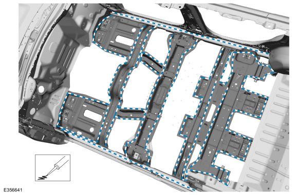
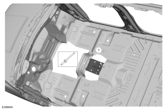
Hood, roof and body side removed for clarity.
NOTE:
Standard wheelbase shown, long wheelbase similar.
-
Depower the SRS .
Refer to: Supplemental Restraint System (SRS) Depowering (501-20B Supplemental Restraint System, General Procedures).
-
On Both Sides:
Remove the seats.
Refer to: Front Seat (501-10A Front Seats, Removal and Installation).
Refer to: Front Seat Track (501-10A Front Seats, Removal and Installation).
Refer to: Second Row Seat (501-10B Second Row Seats, Removal and Installation).
Refer to: Second Row Center Seat (501-10B Second Row Seats, Removal and Installation).
-
Remove the console.
Refer to: Floor Console (501-12 Instrument Panel and Console, Removal and Installation).
-
Remove the carpeting and position all wiring harnesses away from the working area.
-
If Required:
Dimensionally restore the vehicle to pre-damage condition.
Refer to: Body and Frame (501-26 Body Repairs - Vehicle Specific Information and Tolerance Checks, Description and Operation).
-
Remove the front floor panel NVH pads.
Use the General Equipment: Hot Air Gun
Use the General Equipment: Scraper for Straight Edges
-
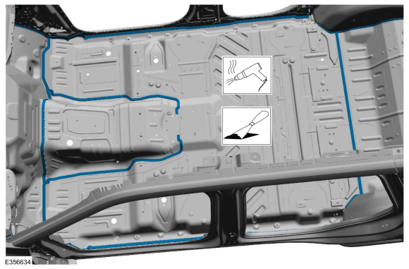
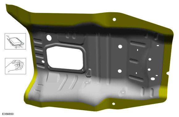
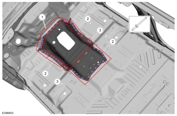
Entire Perimeter:
Remove the front floor panel seam sealer.
Use the General Equipment: Hot Air Gun
Use the General Equipment: Scraper for Straight Edges
-
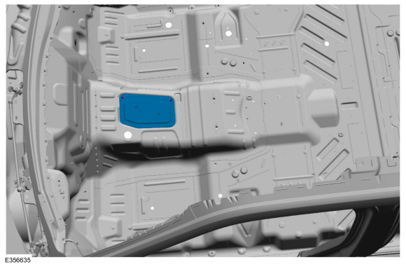
Remove the pushpin fasteners, break the adhesive bond and remove the plate.
-
Remove the fasteners, break the adhesive bond and remove the transmission tunnel.
Use the General Equipment: Belt Sander
Use the General Equipment: Polydrive Bit Socket
Use the General Equipment: Hot Air Gun
-
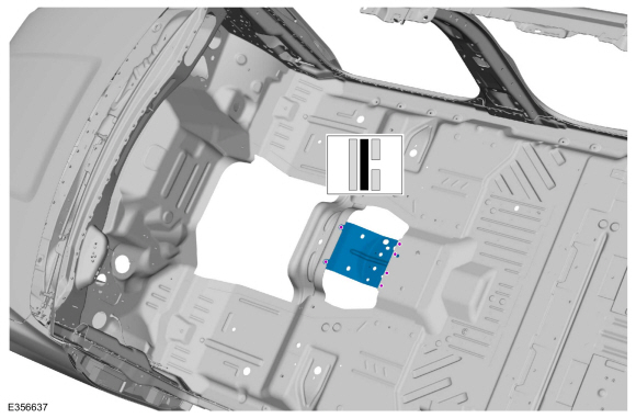
Remove the fasteners, break the adhesive bond and remove the transmission tunnel brace.
Use the General Equipment: Self-Piercing Rivet (SPR) Remover/Installer
Use the General Equipment: Belt Sander
Use the General Equipment: Polydrive Bit Socket
-
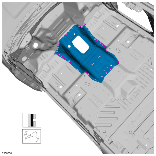
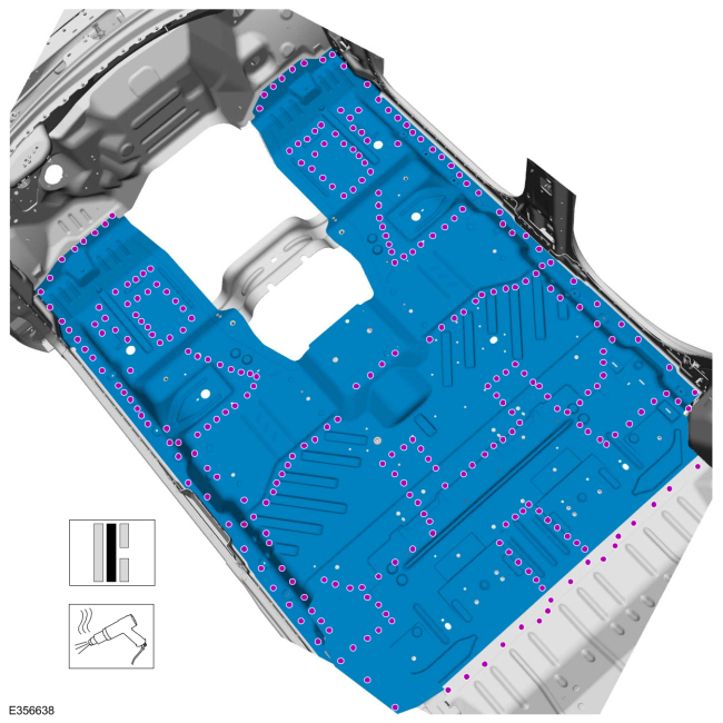
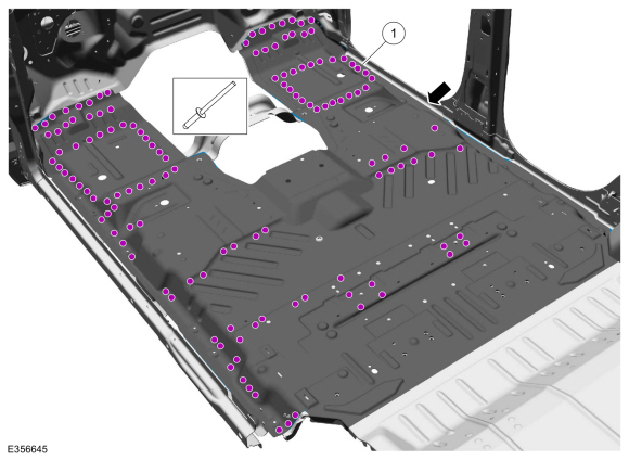
Entire Perimeter:
Remove the fasteners, break the adhesive bond and remove the front floor panel.
Use the General Equipment: Self-Piercing Rivet (SPR) Remover/Installer
Use the General Equipment: Belt Sander
Use the General Equipment: Polydrive Bit Socket
Use the General Equipment: Hot Air Gun
Installation
NOTICE:
Panel sectioning is prohibited within 50 mm of door hinge, door striker, restraints and suspension anchoring points.
NOTE:
Floor panel sectioning is permitted providing recommended
steps are followed. The following assumes full component replacement.
Adjust to meet repair needs.
NOTE:
Self-piercing rivet (SPR) fasteners may not be placed
directly over original self-piercing rivet (SPR) location. They must be
placed adjacent to original location matching original quantity.
NOTE:
Flow-Drill Screw (FDS) fasteners are not reused. Remove and discard.
NOTE:
Aluminum body panels are highly receptive to heat transfer.
With the extensive use of structural adhesives and non-structural
sealers used in vehicle construction, the potential of heat transfer
could impact adhesives and sealers in non-associated panels during the
repair process. Many repairs areas that utilize structural adhesive may
be separated after fastener removal by using a panel chisel along the
joint/flange. Using heat not exceeding 425° F to loosen a bonded panel
should only be done when all panels in the joint will be replaced and
new adhesive applied.
NOTE:
Hood, roof and body side removed for clarity.
NOTE:
Standard wheelbase shown, long wheelbase similar.
-
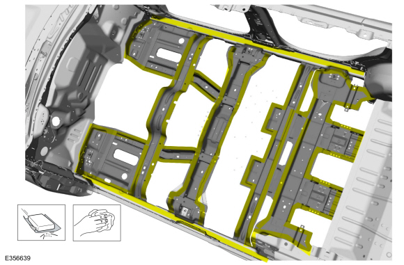
80-120 Grit Sand Paper:
Sand to remove old adhesive, paint and clean.
-
80-120 Grit Sand Paper:
Sand to remove e-coat and clean.
-
Apply adhesive.
Material: Metal Bonding Adhesive
/ TA-1, TA-1-B, 3M™ 08115, LORD Fusor® 108B, Henkel Teroson EP 5055
-
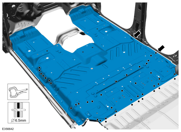
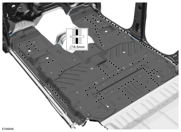
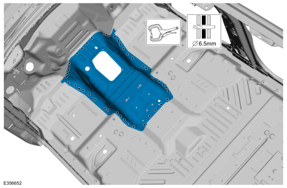
Install, properly position and clamp the front floor panel. Drill for fasteners.
Use the General Equipment: Locking Pliers
Use the General Equipment: 6.5 mm Drill Bit
-
Install the fasteners.
|
Item
|
SPR Number
|
SPR Code
|
Henrob®, Car-O-Liner ®, CMO®, Chief®, Spanesi®, Wielander and Schill® Mandrel
|
Pro- Spot ® Mandrel
|
Blind Rivet
|
Solid
|
Rivnut®
|
|
1
|
-
|
-
|
-
|
-
|
W707638-S900C
|
-
|
-
|
|
2
|
-
|
-
|
-
|
-
|
W702554-S900C
|
-
|
-
|
Use the General Equipment: Rivet Gun
-
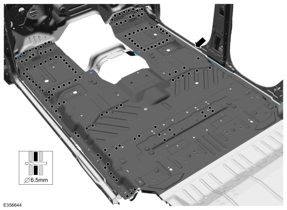
Drill for fasteners.
Use the General Equipment: 6.5 mm Drill Bit
-
Install the fasteners.
|
Item
|
SPR Number
|
SPR Code
|
Henrob®, Car-O-Liner ®, CMO®, Chief®, Spanesi®, Wielander and Schill® Mandrel
|
Pro- Spot ® Mandrel
|
Blind Rivet
|
Solid
|
Rivnut®
|
|
1
|
-
|
-
|
-
|
-
|
W708777-S900C
|
-
|
-
|
Use the General Equipment: Rivet Gun
-
Drill for fasteners.
Use the General Equipment: 6.5 mm Drill Bit
-
Install the fasteners.
|
Item
|
SPR Number
|
SPR Code
|
Henrob®, Car-O-Liner ®, CMO®, Chief®, Spanesi®, Wielander and Schill® Mandrel
|
Pro- Spot ® Mandrel
|
Blind Rivet
|
Solid
|
Rivnut®
|
|
1
|
-
|
-
|
-
|
-
|
W702512-S900C
|
-
|
-
|
Use the General Equipment: Rivet Gun
-
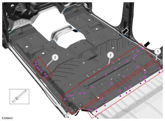
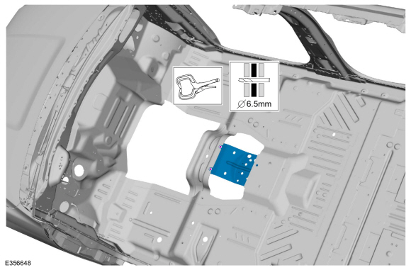
Install, properly position, clamp and drill the transmission tunnel brace.
Use the General Equipment: Locking Pliers
Use the General Equipment: 6.5 mm Drill Bit
-
Install the fasteners.
|
Item
|
SPR Number
|
SPR Code
|
Henrob®, Car-O-Liner ®, CMO®, Chief®, Spanesi®, Wielander and Schill® Mandrel
|
Pro- Spot ® Mandrel
|
Blind Rivet
|
Solid
|
Rivnut®
|
|
1
|
-
|
-
|
-
|
-
|
W702512-S900C
|
-
|
-
|
Use the General Equipment: Rivet Gun
-
80-120 Grit Sand Paper:
Sand to remove e-coat and clean.
-
Apply adhesive.
Material: Metal Bonding Adhesive
/ TA-1, TA-1-B, 3M™ 08115, LORD Fusor® 108B, Henkel Teroson EP 5055
-
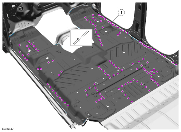
Install, properly position, clamp and drill the transmission tunnel.
Use the General Equipment: Locking Pliers
Use the General Equipment: 6.5 mm Drill Bit
-
Install the fasteners.
|
Item
|
SPR Number
|
SPR Code
|
Henrob®, Car-O-Liner ®, CMO®, Chief®, Spanesi®, Wielander and Schill® Mandrel
|
Pro- Spot ® Mandrel
|
Blind Rivet
|
Solid
|
Rivnut®
|
|
1
|
-
|
-
|
-
|
-
|
W708777-S900C
|
-
|
-
|
|
2
|
-
|
-
|
-
|
-
|
W702512-S900C
|
-
|
-
|
|
3
|
-
|
-
|
-
|
-
|
W707638-S900C
|
-
|
-
|
-
Install the plate and push-pin fasteners.
-
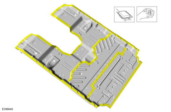
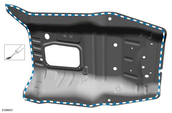
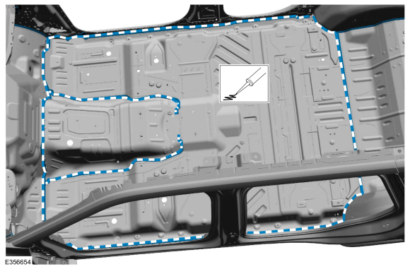
Seam Sealing:
All seams must be sealed to production level.
Material: Seam Sealer
/ TA-2-B, 3M™ 08308, LORD Fusor® 803DTM
-
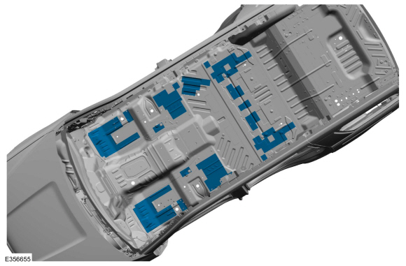
Install locally obtained NVH mastic pads.
-
Refinish the repair using a Ford approved paint system.
-
Restore corrosion protection.
Refer to: Corrosion Prevention (501-25 Body Repairs - General Information, General Procedures).
-
Reposition all wiring harnesses to original location. Install the carpet.
-
Install the console.
Refer to: Floor Console (501-12 Instrument Panel and Console, Removal and Installation).
-
On Both Sides:
Install the seats.
Refer to: Second Row Center Seat (501-10B Second Row Seats, Removal and Installation).
Refer to: Second Row Seat (501-10B Second Row Seats, Removal and Installation).
Refer to: Front Seat Track (501-10A Front Seats, Removal and Installation).
Refer to: Front Seat (501-10A Front Seats, Removal and Installation).
-
Repower the SRS .
Refer to: Supplemental Restraint System (SRS) Repowering (501-20B Supplemental Restraint System, General Procedures).
Special Tool(s) /
General Equipment
6.5 mm Drill Bit
Polydrive Bit Socket
Rivet Gun
Self-Piercing Rivet (SPR) Remover/Installer
Belt Sander
Hot Air Gun
Locking Pliers
Materials
Name
Specification
Metal Bonding AdhesiveTA-1, TA-1-B, 3M™ 08115, LORD Fusor® 108B, Henkel Teroson EP 5055
-
Seam SealerT..
Other information:
Special Tool(s) /
General Equipment
Interior Trim Remover
Removal
NOTE:
Removal steps in this procedure may contain installation details.
Mirror Types
Mirror type 1
Remove the interior rear view mirror.
Loosen the set screw.
Torque:
17 lb.in (1.9 Nm)
Slide the i..
Diagnostics in this manual assume a certain skill level and knowledge of Ford-specific diagnostic practices. REFER to: Diagnostic Methods (100-00 General Information, Description and Operation).
Direct Current/Direct Current (DC/DC) Converter Control Module DTC Chart
DTC
Description
Action
P0A12:11
DC/D..

 Front Floor Panel Crossmember. Removal and Installation