Lincoln Navigator: Rear End Sheet Metal Repairs / Front Floor Panel Crossmember. Removal and Installation
Special Tool(s) /
General Equipment
| 6.5 mm Drill Bit |
| Polydrive Bit Socket |
| Rivet Gun |
| Self-Piercing Rivet (SPR) Remover/Installer |
| Belt Sander |
| Hot Air Gun |
| Locking Pliers |
Materials
| Name |
Specification |
Metal Bonding Adhesive
TA-1, TA-1-B, 3M™ 08115, LORD Fusor® 108B, Henkel Teroson EP 5055 |
-
|
Seam Sealer
TA-2-B, 3M™ 08308, LORD Fusor® 803DTM |
-
|
Removal
NOTICE:
Panel sectioning is prohibited within 50 mm of door hinge, door striker, restraints and suspension anchoring points.
NOTE:
Self-piercing rivet (SPR) fasteners may not be placed
directly over original self-piercing rivet (SPR) location. They must be
placed adjacent to original location matching original quantity.
NOTE:
Blind or solid rivets may be placed in original
self-piercing rivet (SPR) locations after enlarging the hole to 6.5 mm.
Blind or solid rivets must equal factory fasteners in quantity.
NOTE:
Aluminum body panels are highly receptive to heat transfer.
With the extensive use of structural adhesives and non-structural
sealers used in vehicle construction, the potential of heat transfer
could impact adhesives and sealers in non-associated panels during the
repair process. Many repairs areas that utilize structural adhesive may
be separated after fastener removal by using a panel chisel along the
joint/flange. Using heat not exceeding 425° F to loosen a bonded panel
should only be done when all panels in the joint will be replaced and
new adhesive applied.
NOTE:
Flow-Drill Screw (FDS) fasteners are not reusable, remove and discard.
NOTE:
Standard wheelbase shown, long wheelbase similar.
All vehicles
-
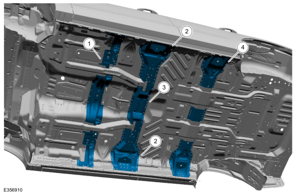
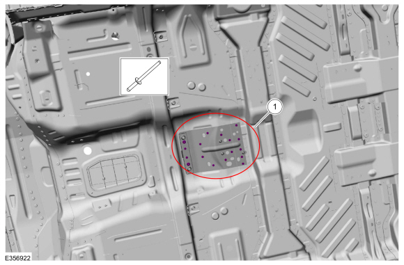
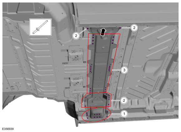
Overview.
|
Item
|
Description
|
|
1
|
Number 1 Front Floor Crossmember
|
|
2
|
Number 2 Front Floor Crossmember Brackets
|
|
3
|
Number 2 Front Floor Crossmember
|
|
4
|
Number 3 Front Floor Crossmember
|
-
Depower the SRS .
Refer to: Supplemental Restraint System (SRS) Depowering (501-20B Supplemental Restraint System, General Procedures).
-
Remove the transmission.
Refer to: Transmission (307-01 Automatic Transmission - 10-Speed Automatic Transmission – 10R80, Removal and Installation).
-
If Required:
Dimensionally restore the vehicle to pre-damage condition.
Refer to: Body and Frame (501-26 Body Repairs - Vehicle Specific Information and Tolerance Checks, Description and Operation).
Number 1 Front Floor Panel Crossmember
-
On Both Sides:
Remove the front floor panel lower reinforcement.
Refer to: Front Floor Panel Lower Reinforcement (501-30 Rear End Sheet Metal Repairs, Removal and Installation).
-
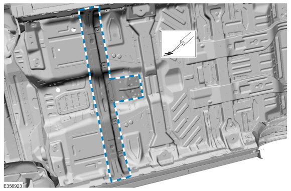
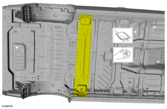
Remove the fasteners and the transmission tunnel reinforcement.
Use the General Equipment: Belt Sander
Use the General Equipment: Polydrive Bit Socket
-
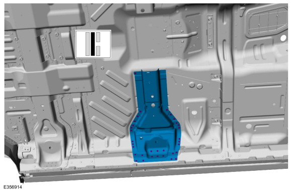
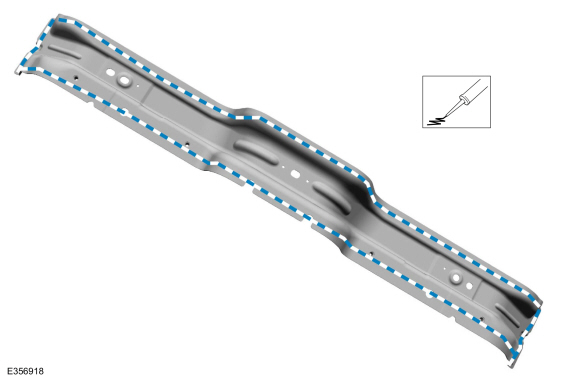
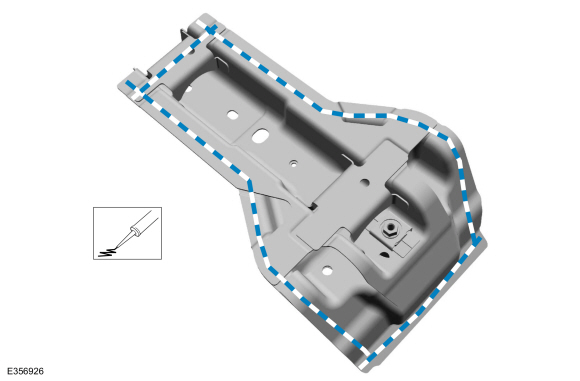
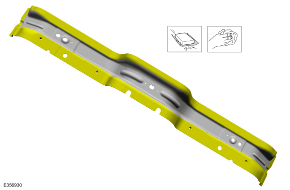
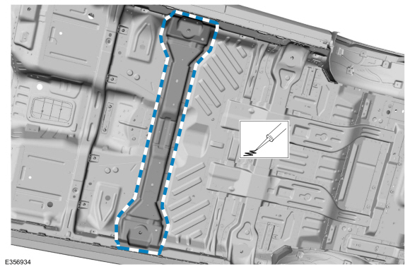
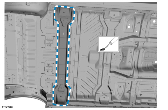
Remove the fasteners, break the adhesive bond and remove the number 1 front floor panel crossmember.
Use the General Equipment: Self-Piercing Rivet (SPR) Remover/Installer
Use the General Equipment: Belt Sander
Use the General Equipment: Polydrive Bit Socket
Use the General Equipment: Hot Air Gun
Number 2 Front Floor Panel Crossmember
-
On Both Sides:
Remove the front floor panel lower reinforcement.
Refer to: Front Floor Panel Lower Reinforcement (501-30 Rear End Sheet Metal Repairs, Removal and Installation).
-
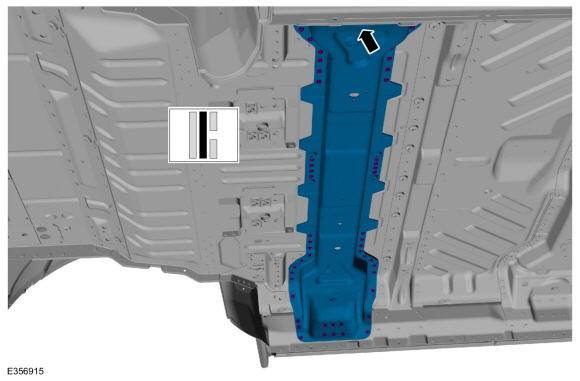
Remove the fasteners, break the adhesive bond and remove the number 2 front floor panel crossmember.
Use the General Equipment: Belt Sander
Use the General Equipment: Polydrive Bit Socket
Use the General Equipment: Hot Air Gun
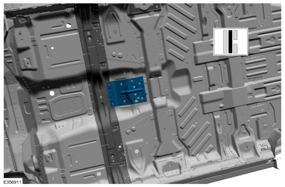
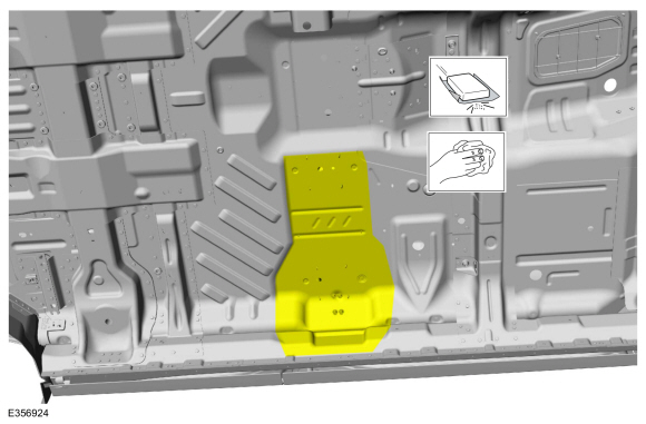
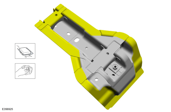
Number 2 Front Floor Panel Crossmember Brackets
NOTE:
Left hand (LH) side shown, right hand (RH) side similar/
-
Remove the number 2 front floor panel crossmember.
-
Remove the fasteners, break the adhesive bond and remove the number 2 front floor panel crossmember bracket.
Use the General Equipment: Self-Piercing Rivet (SPR) Remover/Installer
Use the General Equipment: Belt Sander
Use the General Equipment: Polydrive Bit Socket
Use the General Equipment: Hot Air Gun
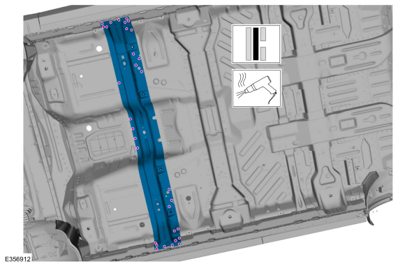
Number 3 Front Floor Panel Crossmember
-
On Both Sides:
Remove the floor panel reinforcement.
Refer to: Floor Panel Reinforcement (501-30 Rear End Sheet Metal Repairs, Removal and Installation).
-
NOTE:
Left hand (LH) side shown, right hand (RH) side similar.
Remove the fasteners, break the adhesive bond and remove the number 3 front floor panel crossmember.
Use the General Equipment: Self-Piercing Rivet (SPR) Remover/Installer
Use the General Equipment: Belt Sander
Use the General Equipment: Polydrive Bit Socket
Use the General Equipment: Hot Air Gun
Installation
NOTICE:
Panel sectioning is prohibited within 50 mm of door hinge, door striker, restraints and suspension anchoring points.
NOTE:
Self-piercing rivet (SPR) fasteners may not be placed
directly over original self-piercing rivet (SPR) location. They must be
placed adjacent to original location matching original quantity.
NOTE:
Blind or solid rivets may be placed in original
self-piercing rivet (SPR) locations after enlarging the hole to 6.5 mm.
Blind or solid rivets must equal factory fasteners in quantity.
NOTE:
Aluminum body panels are highly receptive to heat transfer.
With the extensive use of structural adhesives and non-structural
sealers used in vehicle construction, the potential of heat transfer
could impact adhesives and sealers in non-associated panels during the
repair process. Many repairs areas that utilize structural adhesive may
be separated after fastener removal by using a panel chisel along the
joint/flange. Using heat not exceeding 425° F to loosen a bonded panel
should only be done when all panels in the joint will be replaced and
new adhesive applied.
NOTE:
Flow-Drill Screw (FDS) fasteners are not reusable, remove and discard.
NOTE:
Standard wheelbase shown, long wheelbase similar.
Number 1 Front Floor Panel Crossmember
-
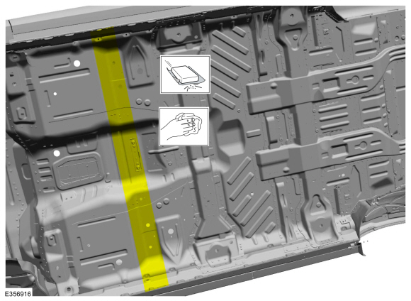
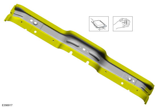
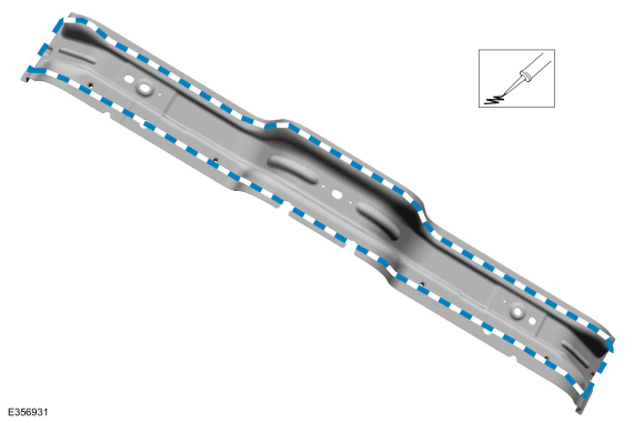
80-120 Grit Sand Paper:
Sand to remove old adhesive, paint and clean.
-
80-120 Grit Sand Paper.
Sand to remove e-coat and clean.
-
Apply adhesive.
Material: Metal Bonding Adhesive
/ TA-1, TA-1-B, 3M™ 08115, LORD Fusor® 108B, Henkel Teroson EP 5055
-
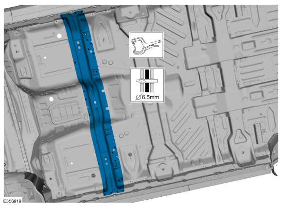
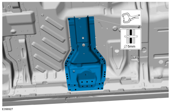
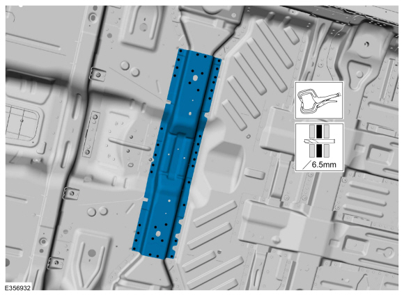
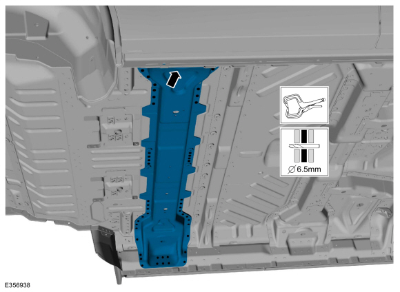
Install, properly position and clamp the number 1 front floor panel crossmember, drill for fasteners.
Use the General Equipment: Locking Pliers
Use the General Equipment: 6.5 mm Drill Bit
-
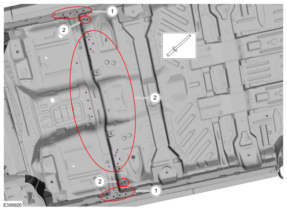
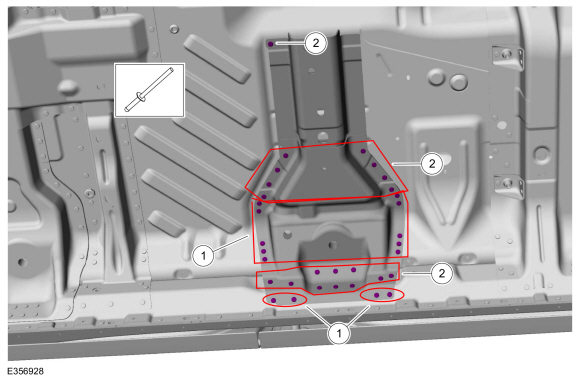
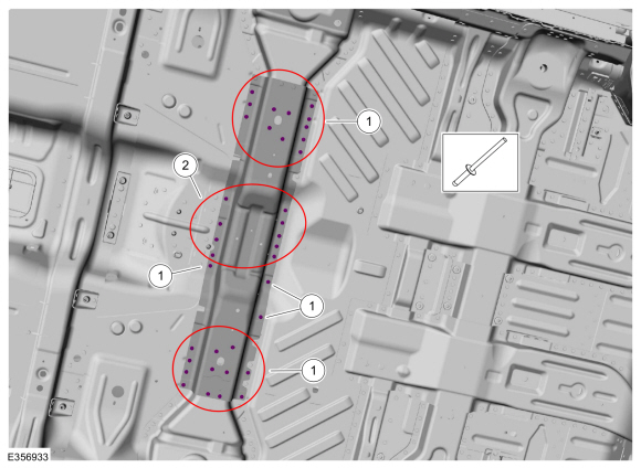
Install the fasteners.
|
Item
|
SPR Number
|
SPR Code
|
Henrob®, Car-O-Liner ®, CMO®, Chief®, Spanesi®, Wielander and Schill® Mandrel
|
Pro- Spot ® Mandrel
|
Blind Rivet
|
Solid Rivet
|
Rivnut®
|
|
1
|
-
|
-
|
-
|
-
|
W708777-S900C
|
-
|
-
|
|
2
|
-
|
-
|
-
|
-
|
W702512-S900C
|
-
|
-
|
Use the General Equipment: Rivet Gun
-
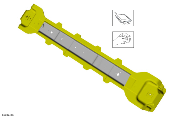
Install, properly position, clamp and drill the transmission tunnel reinforcement.
Use the General Equipment: Locking Pliers
Use the General Equipment: 6.5 mm Drill Bit
-
Install the fasteners.
|
Item
|
SPR Number
|
SPR Code
|
Henrob®, Car-O-Liner ®, CMO®, Chief®, Spanesi®, Wielander and Schill® Mandrel
|
Pro- Spot ® Mandrel
|
Blind Rivet
|
Solid Rivet
|
Rivnut®
|
|
1
|
-
|
-
|
-
|
-
|
W702512-S900C
|
-
|
-
|
Use the General Equipment: Rivet Gun
-
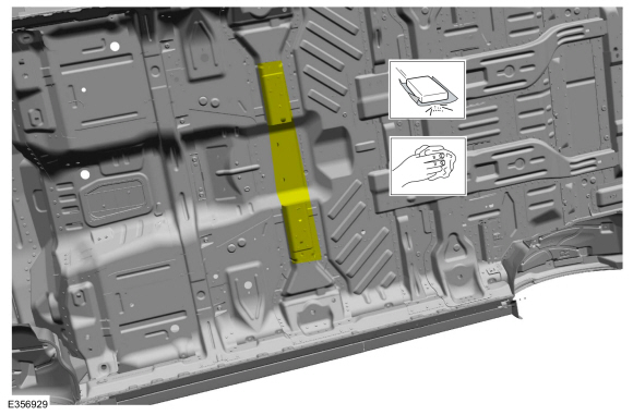
Seam Sealing:
All seams must be sealed to production level.
Material: Seam Sealer
/ TA-2-B, 3M™ 08308, LORD Fusor® 803DTM
-
On Both Sides:
Install the front floor panel lower reinforcement.
Refer to: Front Floor Panel Lower Reinforcement (501-30 Rear End Sheet Metal Repairs, Removal and Installation).
-
Install the transmission.
Refer to: Transmission (307-01 Automatic Transmission - 10-Speed Automatic Transmission – 10R80, Removal and Installation).
Number 2 Front Floor Panel Crossmember Brackets
NOTE:
Left hand (LH) side shown, right hand (RH) side similar.
-
On Both Sides: 80-120 Grit Sand paper:
Sand to remove old adhesive, paint and clean.
-
On both Sides: 80-120 Grit Sand Paper:
Sand to remove e-coat and clean.
-
On Both Sides:
Apply adhesive.
Material: Metal Bonding Adhesive
/ TA-1, TA-1-B, 3M™ 08115, LORD Fusor® 108B, Henkel Teroson EP 5055
-
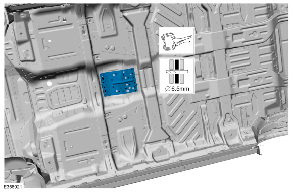
On Both Sides:
Install, properly position, clamp and drill the number 2 front floor panel crossmember bracket.
Use the General Equipment: Locking Pliers
Use the General Equipment: 6.5 mm Drill Bit
-
On Both Sides:
Install the fasteners.
|
Item
|
SPR Number
|
SPR Code
|
Henrob®, Car-O-Liner ®, CMO®, Chief®, Spanesi®, Wielander and Schill® Mandrel
|
Pro- Spot ® Mandrel
|
Blind Rivet
|
Solid Rivet
|
Rivnut®
|
|
1
|
-
|
-
|
-
|
-
|
W708777-S900C
|
-
|
-
|
|
2
|
-
|
-
|
-
|
-
|
W702512-S900C
|
-
|
-
|
Use the General Equipment: Rivet Gun
Number 2 Front floor Panel Crossmember
-
80-120 Grit Sand Paper:
Sand to remove old adhesive, paint and clean.
-
80-120 Grit Sand Paper:
Sand to remove e-coat and clean.
-
Apply adhesive.
Material: Metal Bonding Adhesive
/ TA-1, TA-1-B, 3M™ 08115, LORD Fusor® 108B, Henkel Teroson EP 5055
-
Install, properly position, clamp and drill the number 2 front floor panel crossmember.
Use the General Equipment: Locking Pliers
Use the General Equipment: 6.5 mm Drill Bit
-
Install the fasteners.
|
Item
|
SPR Number
|
SPR Code
|
Henrob®, Car-O-Liner ®, CMO®, Chief®, Spanesi®, Wielander and Schill® Mandrel
|
Pro- Spot ® Mandrel
|
Blind Rivet
|
Solid Rivet
|
Rivnut®
|
|
1
|
-
|
-
|
-
|
-
|
W702554-S900C
|
-
|
-
|
|
2
|
-
|
-
|
-
|
-
|
W702512-S900C
|
-
|
-
|
Use the General Equipment: Rivet Gun
-
Seam Sealing:
All seams must be sealed to production level.
Material: Seam Sealer
/ TA-2-B, 3M™ 08308, LORD Fusor® 803DTM
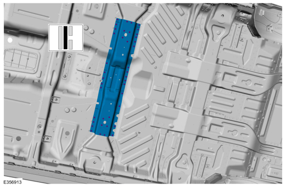
Number 3 Front Floor Panel Crossmember
-
80-120 Grit Sand Paper:
Sand to remove old adhesive, paint and clean.
-
80-120 Grit Sand Paper:
Sand to remove e-coat and clean.
-
Apply adhesive.
Material: Metal Bonding Adhesive
/ TA-1, TA-1-B, 3M™ 08115, LORD Fusor® 108B, Henkel Teroson EP 5055
-
Install, properly position, clamp and drill the number 3 front floor panel crossmember.
Use the General Equipment: Locking Pliers
Use the General Equipment: 6.5 mm Drill Bit
-
Install the fasteners.
|
Item
|
SPR Number
|
SPR Code
|
Henrob®, Car-O-Liner ®, CMO®, Chief®, Spanesi®, Wielander and Schill® Mandrel
|
Pro- Spot ® Mandrel
|
Blind Rivet
|
Solid Rivet
|
Rivnut®
|
|
1
|
-
|
-
|
-
|
-
|
W708777-S900C
|
-
|
-
|
|
2
|
-
|
-
|
-
|
-
|
W702554-S900C
|
-
|
-
|
|
3
|
-
|
-
|
-
|
-
|
W702512-S900C
|
-
|
-
|
Use the General Equipment: Rivet Gun
-
Seam Sealing:
All seams must be sealed to production level.
Material: Seam Sealer
/ TA-2-B, 3M™ 08308, LORD Fusor® 803DTM
-
Install the floor panel reinforcement.
Refer to: Floor Panel Reinforcement (501-30 Rear End Sheet Metal Repairs, Removal and Installation).
All vehicles
-
Refinish the repair using a Ford approved paint system.
-
Restore corrosion protection.
Refer to: Corrosion Prevention (501-25 Body Repairs - General Information, General Procedures).
-
Repower the SRS .
Refer to: Supplemental Restraint System (SRS) Repowering (501-20B Supplemental Restraint System, General Procedures).
Special Tool(s) /
General Equipment
6.5 mm Drill Bit
Scraper for Straight Edges
Rivet Gun
Self-Piercing Rivet (SPR) Remover/Installer
Belt Sander
Hot Air Gun
Locking Pliers
Materials
Name
Specification
Metal Bonding AdhesiveTA-1, TA-1-B, 3M™ 08115, LORD Fusor® 108B, Henkel Teroson EP 5055
-
Seam S..
Other information:
Activation
Refer to: Gasoline and Gasoline-Ethanol Fuel Systems Health and Safety
Precautions (100-00 General Information, Description and Operation).
With the vehicle in NEUTRAL, position it on a hoist.
Refer to: Jacking and Lifting (100-02 Jacking and Lifting, Description and Operation).
NOTE:
The FPDM is located on the LH outboa..
Special Tool(s) /
General Equipment
Flat-Bladed Screwdriver
Interior Trim Remover
Activation
Open the liftgate window glass.
Remove the liftgate latch access cover from the center of the liftgate trim panel.
Use the General Equipment: Interior Trim Remover
In..


 Front Floor Panel Lower Reinforcement. Removal and Installation