Lincoln Navigator: Rear End Sheet Metal Repairs / Floor Panel Section. Removal and Installation
Special Tool(s) / General Equipment
| 6.5 mm Drill Bit | |
| Scraper for Straight Edges | |
| Spherical Cutter | |
| Self-Piercing Rivet (SPR) Remover/Installer | |
| Belt Sander | |
| Blind Rivet Gun | |
| Hot Air Gun | |
| Air Body Saw | |
| Locking Pliers |
Materials
| Name | Specification |
|---|---|
| Metal Bonding Adhesive TA-1, TA-1-B, 3M™ 08115, LORD Fusor® 108B, Henkel Teroson EP 5055 |
- |
| Seam Sealer TA-2-B, 3M™ 08308, LORD Fusor® 803DTM |
- |
Removal
NOTICE: Sectioning may not be performed within 50 mm of restraints, seats, door hinge or door striker anchoring points. Failure to follow this direction may compromise vehicle integrity.
NOTE: Aluminum body panels are highly receptive to heat transfer. With the extensive use of structural adhesives and non-structural sealers used in vehicle construction, the potential of heat transfer could impact adhesives and sealers in non-associated panels during the repair process. Many repairs areas that utilize structural adhesive may be separated after fastener removal by using a panel chisel along the joint/flange. Using heat not exceeding 425° F to loosen a bonded panel should only be done when all panels in the joint will be replaced and new adhesive applied.
NOTE: The floor panel may be sectioned at any point providing restraints, seats, door hinge or striker provisions are met. Adjust the following procedure to meet repair needs.
NOTE: It is recommended when possible to section the floor panel over floor reinforcements. In any case the repair should be sectioned allowing for a lap weld at the sectioning point.
-
Verify the vehicle is dimensionally correct.
Refer to: Body and Frame (501-26 Body Repairs - Vehicle Specific Information and Tolerance Checks, Description and Operation).
-
Depower the supplemental restraint system.
Refer to: Supplemental Restraint System (SRS) Depowering (501-20B Supplemental Restraint System, General Procedures).
-
Remove the interior trim as necessary.
Refer to: A-Pillar Trim Panel (501-05 Interior Trim and Ornamentation, Removal and Installation).
Refer to: B-Pillar Trim Panel (501-05 Interior Trim and Ornamentation, Removal and Installation).
Refer to: C-Pillar Trim Panel (501-05 Interior Trim and Ornamentation, Removal and Installation).
Refer to: D-Pillar Trim Panel - Long Wheelbase (501-05 Interior Trim and Ornamentation, Removal and Installation).
Refer to: D-Pillar Trim Panel - Short Wheelbase (501-05 Interior Trim and Ornamentation, Removal and Installation).
Refer to: Loadspace Trim Panel (501-05 Interior Trim and Ornamentation, Removal and Installation).
-
Remove the seats and console.
Refer to: Floor Console (501-12 Instrument Panel and Console, Removal and Installation).
Refer to: Front Seat (501-10A Front Seats, Removal and Installation).
Refer to: Front Seat Track (501-10A Front Seats, Removal and Installation).
Refer to: Second Row Seat (501-10B Second Row Seats, Removal and Installation).
Refer to: Second Row Center Seat (501-10B Second Row Seats, Removal and Installation).
-
Remove the door opening weather strips and scuff plate.
-
Position the carpeting and wiring harnesses away from the work area.
-
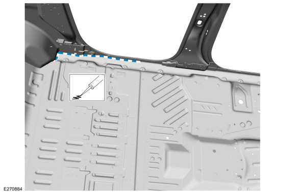
Remove any NVH materials in the repair area.
Use the General Equipment: Hot Air Gun
Use the General Equipment: Scraper for Straight Edges
-
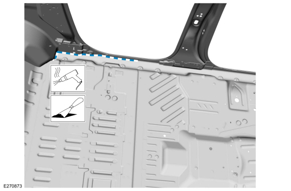
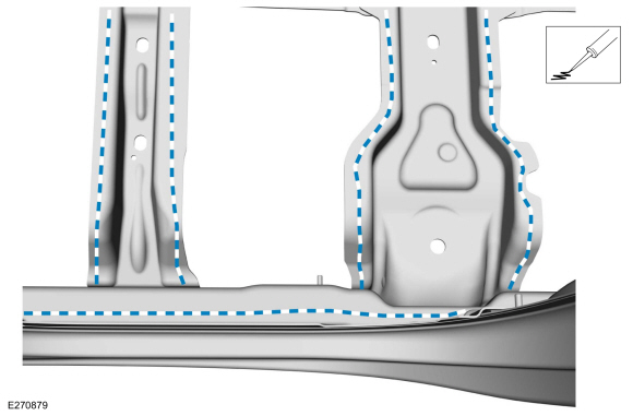
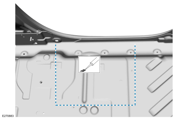
Remove the seam sealer.
Use the General Equipment: Hot Air Gun
Use the General Equipment: Scraper for Straight Edges
 |
-
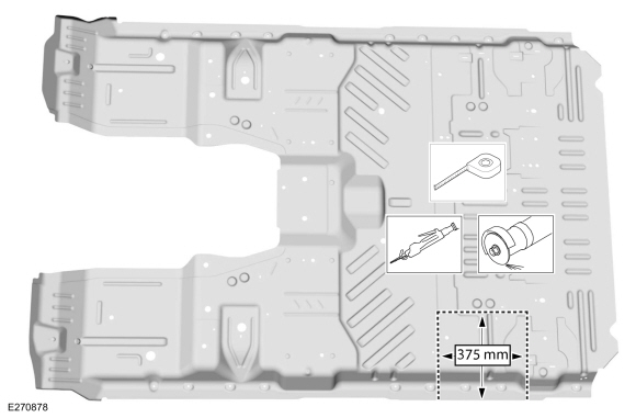
Carefully measure and cut the outer panel only.
Use the General Equipment: Air Body Saw
Use the General Equipment: Spherical Cutter
 |
-
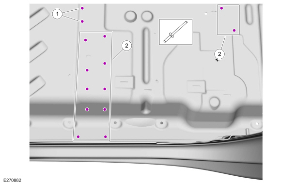
Remove the fasteners.
Use the General Equipment: Self-Piercing Rivet (SPR) Remover/Installer
Use the General Equipment: Belt Sander
 |
-
NOTE: Aluminum body panels are highly receptive to heat transfer. With the extensive use of structural adhesives and non-structural sealers used in vehicle construction, the potential of heat transfer could impact adhesives and sealers in non-associated panels during the repair process. Many repairs areas that utilize structural adhesive may be separated after fastener removal by using a panel chisel along the joint/flange. Using heat not exceeding 425° F to loosen a bonded panel should only be done when all panels in the joint will be replaced and new adhesive applied.
Remove the floor panel section.
 |
Installation
NOTICE: Sectioning may not be performed within 50 mm of restraints, seats, door hinge or door striker anchoring points. Failure to follow this direction may compromise vehicle integrity.
NOTE: The floor panel may be sectioned at any point providing restraints, seats, door hinge or striker provisions are met. Adjust the following procedure to meet repair needs.
NOTE: It is recommended when possible to section the floor panel over floor reinforcements. In any case the repair should be sectioned allowing for a lap weld at the sectioning point.
-
80-120 grit sand paper.
Sand to remove old adhesive and clean.
 |
-
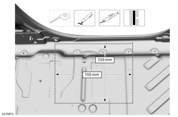
Cut the replacement panel 25 mm larger in length and width to fit vehicle opening creating a lap joint.
Use the General Equipment: Air Body Saw
Use the General Equipment: Spherical Cutter
 |
-
Apply adhesive.
Material: Metal Bonding Adhesive / TA-1, TA-1-B, 3M™ 08115, LORD Fusor® 108B, Henkel Teroson EP 5055
 |
-
Install the floor panel section and clamp in position.
Use the General Equipment: Locking Pliers
 |
-
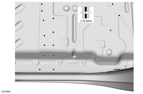
NOTE: Blind or solid rivet fasteners may be used in place of SPR fasteners after enlarging holes to 6.5 mm.
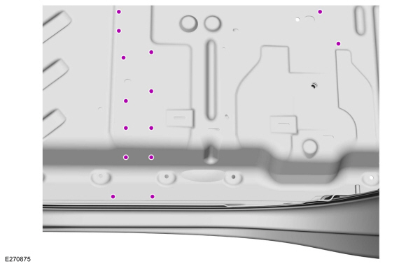
Drill for fasteners.
Use the General Equipment: 6.5 mm Drill Bit
 |
-
NOTE: Blind or solid rivet fasteners may be used in place of SPR fasteners after enlarging holes to 6.5 mm.
Install fasteners.
Use the General Equipment: Blind Rivet GunItem SPR Number SPR Code Henrob® Mandrel Pro-Spot® Mandrel Blind Rivet Solid Rivet Rivnut® 1 - - - - W708777-S900C - - 2 - - - - W702512-S900C - -
 |
-
Metal finishing:
Metal finish using typical aluminum metal finishing techniques and materials.
Refer to: Special Repair Considerations for Aluminum Repairs (501-25 Body Repairs - General Information, Description and Operation).
-
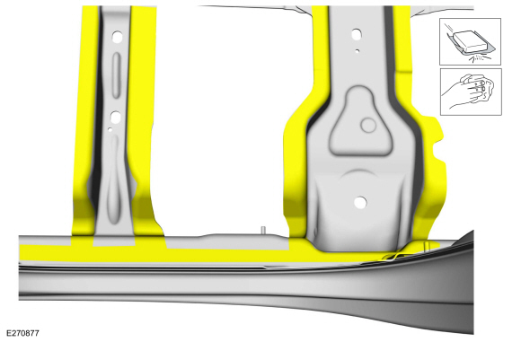
Seam seal the floor panel section lap joints
Material: Seam Sealer / TA-2-B, 3M™ 08308, LORD Fusor® 803DTM
 |
-
Apply locally obtained butyl NVH pads in areas noted during removal.
-
Seam Sealing:
All seams must be sealed to production level.
Material: Seam Sealer / TA-2-B, 3M™ 08308, LORD Fusor® 803DTM
 |
-
Refinish the entire repair using a Ford approved paint system.
-
Restore corrosion protection.
Refer to: Corrosion Prevention (501-25 Body Repairs - General Information, General Procedures).
-
Reposition the wiring harnesses and carpeting.
-
Install the door opening weather strips and scuff plate.
-
Install the interior trim as necessary.
Refer to: A-Pillar Trim Panel (501-05 Interior Trim and Ornamentation, Removal and Installation).
Refer to: B-Pillar Trim Panel (501-05 Interior Trim and Ornamentation, Removal and Installation).
Refer to: C-Pillar Trim Panel (501-05 Interior Trim and Ornamentation, Removal and Installation).
Refer to: D-Pillar Trim Panel - Long Wheelbase (501-05 Interior Trim and Ornamentation, Removal and Installation).
Refer to: D-Pillar Trim Panel - Short Wheelbase (501-05 Interior Trim and Ornamentation, Removal and Installation).
Refer to: Loadspace Trim Panel (501-05 Interior Trim and Ornamentation, Removal and Installation).
-
Install the seats and console.
Refer to: Floor Console (501-12 Instrument Panel and Console, Removal and Installation).
Refer to: Front Seat (501-10A Front Seats, Removal and Installation).
Refer to: Front Seat Track (501-10A Front Seats, Removal and Installation).
Refer to: Second Row Seat (501-10B Second Row Seats, Removal and Installation).
Refer to: Second Row Center Seat (501-10B Second Row Seats, Removal and Installation).
-
Repower the SRS .
Refer to: Supplemental Restraint System (SRS) Repowering (501-20B Supplemental Restraint System, General Procedures).

 Front Floor Panel. Removal and Installation
Special Tool(s) /
General Equipment
6.5 mm Drill Bit
Scraper for Straight Edges
Polydrive Bit Socket
Rivet Gun
Self-Piercing Rivet (SPR) Remover/Installer
Belt Sander
Hot Air Gun
Locking Pliers
Materials
Name
Specification
Metal Bonding AdhesiveTA-1, TA-1-B, 3M™ 08115, LORD Fusor® 108B, Henkel Teroson EP 505..
Other information:
Lincoln Navigator 2018-2026 Workshop Manual: Cooling Module. Removal and Installation
Special Tool(s) / General Equipment Hose Clamp Remover/Installer Removal NOTE: Removal steps in this procedure may contain installation details. With the vehicle in NEUTRAL, position it on a hoist. Refer to: Jacking and Lifting (100-02 Jacking and Lifting, Description and Operation). Drain the cooling system. Refer to: Engine Cooli..
Lincoln Navigator 2018-2026 Workshop Manual: Engine Front Cover. Removal and Installation
Special Tool(s) / General Equipment 205-142 (T80T-4000-J) Installer, Differential Bearing Cone 205-149 (T80T-4000-R) Installer, Spindle Bearing 205-150 (T80T-4000-S) Installer, Spindle Bearing 205-153 (T80T-4000-W) Handle 303-1663Installer, VDOP Seal 307-399Alignment Pins, Transmission Fluid PumpTKIT-2002N-DEWTKIT-2..
Categories
- Manuals Home
- 4th Gen Lincoln Navigator Service Manual (2018 - 2026)
- Transmission Fluid Drain and Refill. General Procedures
- Vehicle Dynamics Control Module (VDM). Removal and Installation
- Front Seat. Removal and Installation
- Windshield Washer Pump. Removal and Installation
- Identification Codes. Description and Operation
Front Stabilizer Bar Link. Removal and Installation
Removal
NOTICE: Suspension fasteners are critical parts that affect the performance of vital components and systems. Failure of these fasteners may result in major service expense. Use the same or equivalent parts if replacement is necessary. Do not use a replacement part of lesser quality or substitute design. Tighten fasteners as specified.
NOTE: Removal steps in this procedure may contain installation details.
With the vehicle in NEUTRAL, position it on a hoist.Refer to: Jacking and Lifting (100-02 Jacking and Lifting, Description and Operation).
NOTICE: Do not use power tools to remove or install the stabilizer bar