Lincoln Navigator: Rear End Sheet Metal Repairs / Floor Panel Reinforcement. Removal and Installation
Special Tool(s) / General Equipment
| 6.5 mm Drill Bit | |
| Scraper for Straight Edges | |
| Self-Piercing Rivet (SPR) Remover/Installer | |
| Belt Sander | |
| Blind Rivet Gun | |
| Hot Air Gun | |
| Locking Pliers |
Materials
| Name | Specification |
|---|---|
| Metal Bonding Adhesive TA-1, TA-1-B, 3M™ 08115, LORD Fusor® 108B, Henkel Teroson EP 5055 |
- |
| Seam Sealer TA-2-B, 3M™ 08308, LORD Fusor® 803DTM |
- |
Removal
NOTICE: Panel sectioning is prohibited within 50 mm of door hinge, door striker, restraints and suspension anchoring points.
NOTE: Self-piercing rivet (SPR) fasteners may not be placed directly over original SPR location. They must be placed adjacent to original location matching original quantity.
NOTE: Aluminum body panels are highly receptive to heat transfer. With the extensive use of structural adhesives and non-structural sealers used in vehicle construction, the potential of heat transfer could impact adhesives and sealers in non-associated panels during the repair process. Many repair areas that utilize structural adhesives may be separated after fastener removal by using a panel chisel along the joint/flange. Using heat not exceeding 425° F to loosen a bonded panel should only be done when all panels in the joint will be replaced and new adhesive applied.
NOTE: The floor panel reinforcement may be sectioned providing the sectioning guidelines are adhered to. The following procedure assumes full component replacement. Adjust to meet repair needs.
NOTE: LH side shown, RH side similar.
NOTE: Long wheelbase shown, short wheelbase similar.
-
Depower the SRS .
Refer to: Supplemental Restraint System (SRS) Depowering (501-20B Supplemental Restraint System, General Procedures).
-
If Necessary:
Dimensionally restore the vehicle to pre-damage condition.
Refer to: Body and Frame (501-26 Body Repairs - Vehicle Specific Information and Tolerance Checks, Description and Operation).
-
Remove the A, B and C-pillar trim.
Refer to: A-Pillar Trim Panel (501-05 Interior Trim and Ornamentation, Removal and Installation).
Refer to: B-Pillar Trim Panel (501-05 Interior Trim and Ornamentation, Removal and Installation).
Refer to: C-Pillar Trim Panel (501-05 Interior Trim and Ornamentation, Removal and Installation).
-
Remove the front and second row seats.
Refer to: Front Seat (501-10A Front Seats, Removal and Installation).
Refer to: Second Row Seat (501-10B Second Row Seats, Removal and Installation).
-
Position the carpet and all wiring harnesses away from the working area.
-
Remove the A-pillar reinforcement.
Refer to: A-Pillar Outer Panel Section and Reinforcement (501-29 Side Panel Sheet Metal Repairs, Removal and Installation).
-
Remove the rocker panel reinforcement.
Refer to: Rocker Panel Inner Reinforcement (501-29 Side Panel Sheet Metal Repairs, Removal and Installation).
-
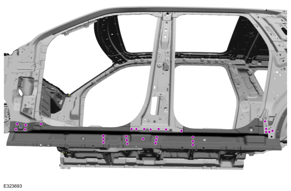
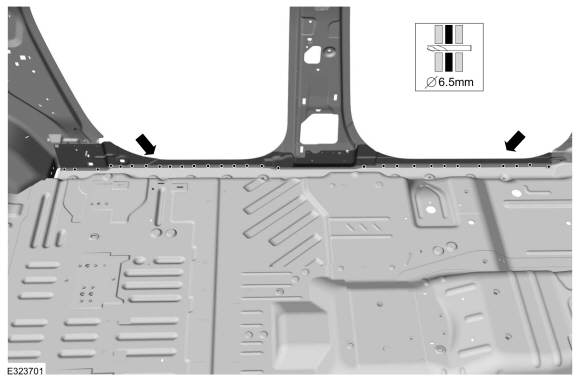
Remove the fasteners.
Use the General Equipment: Self-Piercing Rivet (SPR) Remover/Installer
Use the General Equipment: Belt Sander
 |
-
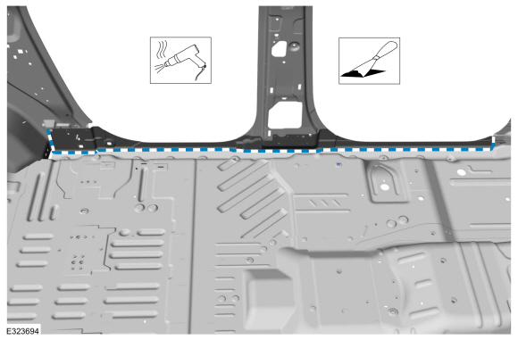
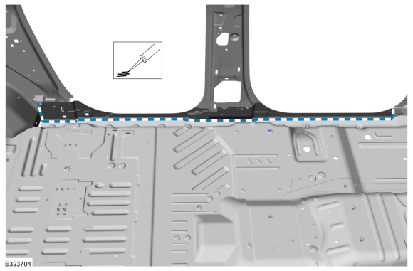
Remove the seam sealer.
Use the General Equipment: Hot Air Gun
Use the General Equipment: Scraper for Straight Edges
 |
-
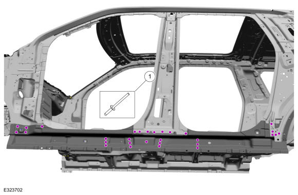
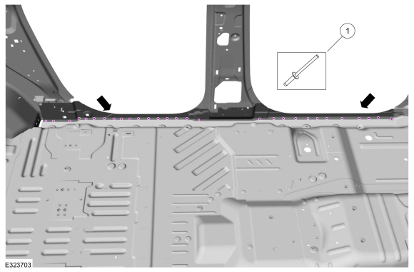
Remove the fasteners.
Use the General Equipment: Self-Piercing Rivet (SPR) Remover/Installer
Use the General Equipment: Belt Sander
 |
-
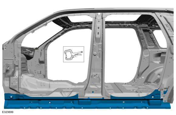
Break the adhesive bond and remove the floor side reinforcement.
Use the General Equipment: Hot Air Gun
 |
Installation
NOTICE: Body side sectioning is prohibited within 50 mm of door hinge, door striker, restraints and suspension anchoring points.
NOTE: Self-piercing rivet (SPR) fasteners may not be placed directly over original SPR location. They must be placed adjacent to original location matching original quantity.
NOTE: Aluminum body panels are highly receptive to heat transfer. With the extensive use of structural adhesives and non-structural sealers used in vehicle construction, the potential of heat transfer could impact adhesives and sealers in non-associated panels during the repair process. Many repair areas that utilize structural adhesives may be separated after fastener removal by using a panel chisel along the joint/flange. Using heat not exceeding 425° F to loosen a bonded panel should only be done when all panels in the joint will be replaced and new adhesive applied.
NOTE: Left hand (LH) side shown, right hand (RH) side similar.
NOTE: Long wheelbase shown, short wheelbase similar.
-
80-120 Grit Sand Paper:
Sand to remove old adhesive, e-coat and clean.
 |
-
Apply adhesive.
Material: Metal Bonding Adhesive / TA-1, TA-1-B, 3M™ 08115, LORD Fusor® 108B, Henkel Teroson EP 5055
 |
-
Install, properly position and clamp the floor panel reinforcement.
Use the General Equipment: Locking Pliers
 |
-
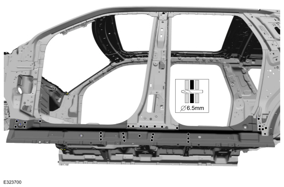
Drill for fasteners.
Use the General Equipment: 6.5 mm Drill Bit
 |
-
Drill for fasteners.
Use the General Equipment: 6.5 mm Drill Bit
 |
-
Install the fasteners.
Use the General Equipment: Blind Rivet GunItem SPR Number SPR Code Henrob®, Car-O-Liner ®, CMO®, Chief®, Spanesi®, Wielander and Schill® Mandrel Pro-Spot® Mandrel Blind Rivet Solid Rivet Riv-Nut® 1 - - - - W708777-S900C - -
 |
-
Install the fasteners.
Use the General Equipment: Blind Rivet GunItem SPR Number SPR Code Henrob®, Car-O-Liner ®, CMO®, Chief®, Spanesi®, Wielander and Schill® Mandrel Pro-Spot® Mandrel Blind Rivet Solid Rivet Riv-Nut® 1 - - - - W702512-S900C - -
 |
-
Seam Sealing:
All seams must be sealed to production level.
Material: Seam Sealer / TA-2-B, 3M™ 08308, LORD Fusor® 803DTM
 |
-
Install the rocker reinforcement.
Refer to: Rocker Panel Inner Reinforcement (501-29 Side Panel Sheet Metal Repairs, Removal and Installation).
-
Install the A-pillar reinforcement.
Refer to: A-Pillar Outer Panel Section and Reinforcement (501-29 Side Panel Sheet Metal Repairs, Removal and Installation).
-
Refinish the entire repair using a Ford approved paint system.
-
Restore corrosion protection.
Refer to: Corrosion Prevention (501-25 Body Repairs - General Information, General Procedures).
-
Position all wiring harnesses and the carpet to original location.
-
Install the front and second row seats.
Refer to: Second Row Seat (501-10B Second Row Seats, Removal and Installation).
Refer to: Front Seat (501-10A Front Seats, Removal and Installation).
-
Install the A, B and C-pillar trim.
Refer to: C-Pillar Trim Panel (501-05 Interior Trim and Ornamentation, Removal and Installation).
Refer to: B-Pillar Trim Panel (501-05 Interior Trim and Ornamentation, Removal and Installation).
Refer to: A-Pillar Trim Panel (501-05 Interior Trim and Ornamentation, Removal and Installation).
-
Repower the SRS .
Refer to: Supplemental Restraint System (SRS) Repowering (501-20B Supplemental Restraint System, General Procedures).

 Floor Panel Section. Removal and Installation
Special Tool(s) /
General Equipment
6.5 mm Drill Bit
Scraper for Straight Edges
Spherical Cutter
Self-Piercing Rivet (SPR) Remover/Installer
Belt Sander
Blind Rivet Gun
Hot Air Gun
Air Body Saw
Locking Pliers
Materials
Name
Specification
Metal Bonding AdhesiveTA-1, TA-1-B, 3M™ 08115, LORD Fusor® 108B..
Other information:
Lincoln Navigator 2018-2026 Workshop Manual: Satellite Radio / Global Positioning System (GPS) Splitter / Cable. Removal and Installation
Removal NOTE: Removal steps in this procedure may contain installation details. Remove the ACM . Refer to: Information and Entertainment System - Component Location (415-00 Information and Entertainment System - General Information - Vehicles With: SYNC 4, Description and Operation). Remove the glove compartment door and glove compartment storage b..
Lincoln Navigator 2018-2026 Workshop Manual: Interior Camera System. Diagnosis and Testing
Diagnostic Trouble Code (DTC) Chart Diagnostics in this manual assume a certain skill level and knowledge of Ford-specific diagnostic practices. REFER to: Diagnostic Methods (100-00 General Information, Description and Operation). Module DTC Description Action CMR B115E:49 Camera Module: Internal Electronic Failure GO to Pinpoint Test A CMR B115E:54 Cam..
Categories
- Manuals Home
- 4th Gen Lincoln Navigator Service Manual (2018 - 2026)
- Liftgate Trim Panel. Removal and Installation
- Brake Service Mode Activation and Deactivation. General Procedures
- Front Seat. Removal and Installation
- Rear Bumper. Removal and Installation
- Vehicle Dynamics Control Module (VDM). Removal and Installation
Diagnostic Methods. Description and Operation
This document provides critical diagnostic knowledge required for successful repair outcomes. It identifies technical competencies expected by users of this manual.
Ford Diagnostic Assumptions
Ford diagnostics assume the vehicle concern described by the test title is currently present. Exceptions to this rule are noted in each test. Do not replace modules or other components as directed by a diagnostic if the concern is not present at the time of testing.