• Navigator Manuals
  • Service
  • New
  • Top
  • Sitemap
Lincoln Navigator Manuals

Lincoln Navigator: Intake Air Distribution and Filtering - 3.5L EcoBoost (272kW/370PS) / Intake Air Pressure and Temperature. Diagnosis and Testing

Lincoln Navigator 2018-2025 Workshop Manual / Engine / Intake Air Distribution and Filtering - 3.5L EcoBoost (272kW/370PS) / Intake Air Pressure and Temperature. Diagnosis and Testing

Diagnostic Trouble Code (DTC) Chart

Diagnostics in this manual assume a certain skill level and knowledge of Ford-specific diagnostic practices.
REFER to: Diagnostic Methods (100-00 General Information, Description and Operation).


Module DTC Description Action
PCM P007A:00 Charge Air Cooler Temperature Sensor Circuit (Bank 1): No Sub Type Information GO to Pinpoint Test DN
PCM P007B:00 Charge Air Cooler Temperature Sensor Circuit Range/Performance (Bank 1): No Sub Type Information GO to Pinpoint Test DN
PCM P007C:00 Charge Air Cooler Temperature Sensor Circuit Low (Bank 1): No Sub Type Information GO to Pinpoint Test DN
PCM P007D:00 Charge Air Cooler Temperature Sensor Circuit High (Bank 1): No Sub Type Information GO to Pinpoint Test DN
PCM P0096:00 Intake Air Temperature Sensor 2 Circuit Range/Performance (Bank 1): No Sub Type Information GO to Pinpoint Test DN
PCM P0097:00 Intake Air Temperature Sensor 2 Circuit Low (Bank 1): No Sub Type Information GO to Pinpoint Test DN
PCM P0098:00 Intake Air Temperature Sensor 2 Circuit High (Bank 1): No Sub Type Information GO to Pinpoint Test DN
PCM P00CE:00 Intake Air Temperature Measurement System - Multiple Sensor Correlation (Bank 1): No Sub Type Information GO to Pinpoint Test DN
PCM P0106:00 Manifold Absolute Pressure/Barometric Pressure Sensor Circuit Range/Performance: No Sub Type Information GO to Pinpoint Test DM
PCM P0107:00 Manifold Absolute Pressure/Barometric Pressure Sensor Circuit Low: No Sub Type Information GO to Pinpoint Test DM
PCM P0108:00 Manifold Absolute Pressure/Barometric Pressure Sensor Circuit High: No Sub Type Information GO to Pinpoint Test DM
PCM P0109:00 Manifold Absolute Pressure/Barometric Pressure Sensor Circuit Intermittent: No Sub Type Information GO to Pinpoint Test DM
PCM P0235:00 Turbocharger/Supercharger Boost Sensor 'A' Circuit: No Sub Type Information GO to Pinpoint Test DM
PCM P0236:00 Turbocharger/Supercharger Boost Sensor 'A' Circuit Range/Performance: No Sub Type Information GO to Pinpoint Test DM
PCM P0237:00 Turbocharger/Supercharger Boost Sensor 'A' Circuit Low: No Sub Type Information GO to Pinpoint Test DM
PCM P0238:00 Turbocharger/Supercharger Boost Sensor 'A' Circuit High: No Sub Type Information GO to Pinpoint Test DM
PCM P2227:00 Barometric Pressure Sensor 'A' Circuit Range/Performance: No Sub Type Information GO to Pinpoint Test DO
PCM P2228:00 Barometric Pressure Sensor 'A' Circuit Low: No Sub Type Information GO to Pinpoint Test DO
PCM P2229:00 Barometric Pressure Sensor 'A' Circuit High: No Sub Type Information GO to Pinpoint Test DO
PCM U060B:00 Lost Communication With Turbocharger/Supercharger Boost Sensor 'A': No Sub Type Information GO to Pinpoint Test DM
PCM U066D:00 Lost Communication With Charge Air Cooler Temperature Sensor Bank 1: No Sub Type Information GO to Pinpoint Test DN

Global Customer Symptom Code (GCSC) Chart

Diagnostics in this manual assume a certain skill level and knowledge of Ford-specific diagnostic practices.
REFER to: Diagnostic Methods (100-00 General Information, Description and Operation).


Symptom Action
Driving Performance > Runs Rough > Acceleration > Always GO to Pinpoint Test DM
Driving Performance > Runs Rough > Cruise/ Steady Speed > Always GO to Pinpoint Test DM
Driving Performance > Runs Rough > Deceleration > Always GO to Pinpoint Test DM
Driving Performance > Runs Rough > All Running Modes > Always GO to Pinpoint Test DM
Driving Performance > Idle Quality > Fast > Always GO to Pinpoint Test DM
Driving Performance > Idle Quality > Rolling > Always GO to Pinpoint Test DM
Driving Performance > Idle Quality > Slow > Always GO to Pinpoint Test DM
Driving Performance > Idle Quality > Slow Return > Always GO to Pinpoint Test DM
Driving Performance > Idle Quality > Rough > Always GO to Pinpoint Test DM
Driving Performance > Stalls/Quits > At Idle > Always GO to Pinpoint Test DM
Driving Performance > Stalls/Quits > Acceleration > Always GO to Pinpoint Test DM
Driving Performance > Stalls/Quits > Cruise/ Steady Speed > Always GO to Pinpoint Test DM
Driving Performance > Hesitates/Stumble > Cruise/ Steady Speed > Always GO to Pinpoint Test DM
Driving Performance > Engine Surge > At Idle > Always GO to Pinpoint Test DM
Driving Performance > Engine Surge > Acceleration > Always GO to Pinpoint Test DM
Driving Performance > Engine Surge > Cruise/ Steady Speed > Always GO to Pinpoint Test DM
Driving Performance > Engine Surge > Deceleration > Always GO to Pinpoint Test DM

Pinpoint Tests


PINPOINT TEST DM: MANIFOLD PRESSURE SENSORS
Introduction

NOTE: Refer to the appropriate Wiring Diagrams Cell for schematic and connector information

Normal Operation and Fault Conditions

Refer to the DTC Fault Trigger Conditions.

DTC Fault Trigger Conditions

DTC Description Fault Trigger Condition
PCM P0106:00 Manifold Absolute Pressure/Barometric Pressure Sensor Circuit Range/Performance: No Sub Type Information Sets when the PCM detects the MAP PID does not correlate with the BARO or the TCBP PID . This DTC may be accompanied by other Diagnostic Trouble Codes (DTCs). Check for other Diagnostic Trouble Codes (DTCs) and diagnose those first.
PCM P0107:00 Manifold Absolute Pressure/Barometric Pressure Sensor Circuit Low: No Sub Type Information Sets when the PCM detects the MAP sensor operating voltage is below the minimum calibrated parameter of 0.024 volt.
PCM P0108:00 Manifold Absolute Pressure/Barometric Pressure Sensor Circuit High: No Sub Type Information Sets when the PCM detects the MAP sensor operating voltage is greater than the maximum allowable calibrated parameter of 4.96 volts.
PCM P0109:00 Manifold Absolute Pressure/Barometric Pressure Sensor Circuit Intermittent: No Sub Type Information Sets when the PCM detects the MAP sensor signal is intermittent.
PCM P0235:00 Turbocharger/Supercharger Boost Sensor 'A' Circuit: No Sub Type Information Sets when the PCM detects the Turbocharger Boost Pressure (TCBP) sensor circuit value is not within the expected range.
PCM P0236:00 Turbocharger/Supercharger Boost Sensor 'A' Circuit Range/Performance: No Sub Type Information Sets when the PCM detects the Turbocharger Boost Pressure (TCBP) PID does not correlate with the BARO or the MAP PID . This DTC may be accompanied by other Diagnostic Trouble Codes (DTCs). Check for other Diagnostic Trouble Codes (DTCs) and diagnose those first. Check the intake air system for leaks and restrictions.
PCM P0237:00 Turbocharger/Supercharger Boost Sensor 'A' Circuit Low: No Sub Type Information Sets when the PCM detects a short to ground from the Turbocharger boost pressure (TCBP) circuit. Check the harness for intermittent concerns, incorrect connections, routing, alterations and damage due to contact with other components. This DTC may be accompanied by other Diagnostic Trouble Codes (DTCs). Check for other Diagnostic Trouble Codes (DTCs) and diagnose those first.
PCM P0238:00 Turbocharger/Supercharger Boost Sensor 'A' Circuit High: No Sub Type Information Sets when the PCM detects there is an open circuit or high voltage from the turbocharger boost pressure (TCBP) sensor circuit. Check the harness for intermittent concerns, incorrect connections, routing, alterations and damage due to contact with other components. This DTC may be accompanied by other Diagnostic Trouble Codes (DTCs). Check for other Diagnostic Trouble Codes (DTCs) and diagnose those first.
PCM U060B:00 Lost Communication With Turbocharger/Supercharger Boost Sensor 'A': No Sub Type Information Sets when the PCM no longer receives a signal from the Turbocharger Boost Pressure (TCBP) sensor.

Possible Sources

  • MAP / IAT2 sensor circuitry concern
  • Turbocharger boost pressure/CAC temperature sensor circuitry concern
  • MAP / IAT2 sensor (9F479)
  • Turbocharger boost pressure /CAC temperature sensor (9F479)
  • PCM (12A650)
PINPOINT TEST DN: PRESSURE AND TEMPERATURE SENSORS
Introduction

NOTE: Refer to the appropriate Wiring Diagrams Cell for schematic and connector information

Normal Operation and Fault Conditions

Voltage values calculated for VREF equals 5 volts. These values can vary by 15% due to sensor and VREF variations.

Refer to the DTC Fault Trigger Conditions.

DTC Fault Trigger Conditions

DTC Description Fault Trigger Condition
PCM P007A:00 Charge Air Cooler Temperature Sensor Circuit (Bank 1): No Sub Type Information This DTC sets when the charge air cooler temperature (CACT) sensor value is not within the expected range.
PCM P007B:00 Charge Air Cooler Temperature Sensor Circuit Range/Performance (Bank 1): No Sub Type Information Sets when the PCM detects the CAC temperature sensor value does not correlate with the IAT sensor value or the IAT2 sensor value at ignition ON after a calibrated soak period (typically 6 to 8 hours). This DTC also sets if the CAC temperature sensor value exceeds the maximum calibrated temperature threshold while driving. Check temperature values while engine is at ambient temperature, cold soak the engine for a minimum of 6 hours if necessary. Check airflow through CAC , remove debris if necessary. This DTC may be accompanied by other Diagnostic Trouble Codes (DTCs). Check for other Diagnostic Trouble Codes (DTCs) and diagnose those first.
PCM P007C:00 Charge Air Cooler Temperature Sensor Circuit Low (Bank 1): No Sub Type Information Sets when the PCM detects the CAC temperature is greater than a calibrated value or a short to ground is detected in the CAC temperature circuit. This DTC may be accompanied by other Diagnostic Trouble Codes (DTCs). Check for other Diagnostic Trouble Codes (DTCs) and diagnose those first.
PCM P007D:00 Charge Air Cooler Temperature Sensor Circuit High (Bank 1): No Sub Type Information Sets when the PCM detects the CAC temperature is lower than a calibrated value or an open or short to voltage is detected in the CAC temperature circuit. This DTC may be accompanied by other Diagnostic Trouble Codes (DTCs). Check for other Diagnostic Trouble Codes (DTCs) and diagnose those first.
PCM P0096:00 Intake Air Temperature Sensor 2 Circuit Range/Performance (Bank 1): No Sub Type Information Sets when the PCM detects the IAT2 sensor value does not correlate with the CAC temperature sensor value or the IAT sensor value at ignition ON after a calibrated soak period (typically 6 to 8 hours). This DTC also sets if the IAT2 sensor value exceeds the maximum calibrated temperature threshold while driving. Aftermarket heaters that are attached to the engine, transmission or battery may cause DTC P0096 to set in cold weather climates after a 6 hour soak period. This DTC may be accompanied by other Diagnostic Trouble Codes (DTCs). Check for other Diagnostic Trouble Codes (DTCs) and diagnose those first.
PCM P0097:00 Intake Air Temperature Sensor 2 Circuit Low (Bank 1): No Sub Type Information Sets when the PCM detects the IAT2 sensor signal is less than the self-test minimum. The IAT2 sensor minimum is 0.2 volt. Monitor the IAT2 PID value. A typical IAT2 sensor temperature should be greater than the IAT sensor temperature.
PCM P0098:00 Intake Air Temperature Sensor 2 Circuit High (Bank 1): No Sub Type Information Sets when the PCM detects the IAT2 sensor signal is greater than the self-test maximum. The IAT2 sensor maximum is 4.6 volts. Monitor the IAT2 PID value. A typical IAT2 sensor temperature should be greater than the IAT sensor temperature.
PCM P00CE:00 Intake Air Temperature Measurement System - Multiple Sensor Correlation (Bank 1): No Sub Type Information Sets when the PCM detects the charge air cooler (CAC) temperature, IAT and the IAT2 PIDs are each greater than 16.67ºC (30ºF) different from each other at start up or that each sensor is out of the calibrated range at engine start up after a soak period of at least 6 hours when a block heater is not used. Compare all sensor readings to the ambient temperature to determine which sensor is reading correctly. This DTC may be accompanied by other Diagnostic Trouble Codes (DTCs). Check for other Diagnostic Trouble Codes (DTCs) and diagnose those first.
PCM U066D:00 Lost Communication With Charge Air Cooler Temperature Sensor Bank 1: No Sub Type Information This DTC sets when the PCM no longer receives a signal from the charge air cooler temperature (CACT) sensor.

Possible Sources

  • IAT sensor circuitry concern
  • MAP / IAT2 sensor circuitry concern
  • Turbocharger boost pressure/CAC temperature sensor circuitry concern
  • IAT sensor
  • MAP / IAT2 sensor (9F479)
  • Turbocharger boost pressure/CAC temperature sensor (9F479)
  • PCM (12A650)
PINPOINT TEST DO: BAROMETRIC PRESSURE (BARO) SENSOR
Introduction

NOTE: Refer to the appropriate Wiring Diagrams Cell for schematic and connector information

Normal Operation and Fault Conditions
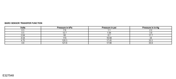
Refer to the DTC Fault Trigger Conditions.

DTC Fault Trigger Conditions

DTC Description Fault Trigger Condition
PCM P2227:00 Barometric Pressure Sensor 'A' Circuit Range/Performance: No Sub Type Information Sets when the PCM detects either of the following conditions are present:
  • When the BARO PID does not correlate with the TCBP and the MAP PIDs at ignition ON, engine OFF.
  • When the MAP and TCBP PIDs correlate with the engine running, but the TCBP PID does not correlate with the BARO PID at idle.
This DTC is only operational between 1,000 feet below sea level to 15,000 feet above sea level, it should be disregarded if set outside the operational range.
PCM P2228:00 Barometric Pressure Sensor 'A' Circuit Low: No Sub Type Information Sets when the PCM detects the BARO reading is abnormally low indicating an extreme high altitude. When the BARO signal is less than the calibrated threshold for greater than 100 ms, a concern is indicated. This DTC is only operational between 1,000 feet below sea level to 15,000 feet above sea level, it should be disregarded if set outside the operational range.
PCM P2229:00 Barometric Pressure Sensor 'A' Circuit High: No Sub Type Information Sets when the PCM detects the barometric pressure (BARO) reading is abnormally high indicating an extreme low altitude. When the BARO signal is greater than a calibrated threshold for greater than 100 ms, a concern is indicated. This DTC is only operational between 1,000 feet below sea level to 15,000 feet above sea level, it should be disregarded if set outside the operational range.

Possible Sources

  • BARO sensor
  • PCM (12A650)

    Intake Air Flow. Diagnosis and Testing

    Diagnostic Trouble Code (DTC) Chart Diagnostics in this manual assume a certain skill level and knowledge of Ford-specific diagnostic practices. REFER to: Diagnostic Methods (100-00 General Information, Description and Operation)...

    Charge Air Cooler (CAC) Cleaning. General Procedures

    Materials Name Specification Motorcraft® Metal Brake Parts CleanerPM-4-A, PM-4-B, APM-4-C -  Cleaning NOTICE: Do not use a high-pressure power washer to clean the CAC or damage to the CAC may occur...

    Other information:

    Lincoln Navigator 2018-2025 Workshop Manual: Rear Temperature Door Actuator. Removal and Installation


    Removal NOTE: Removal steps in this procedure may contain installation details. Remove the RH loadspace trim panel. Refer to: Loadspace Trim Panel (501-05 Interior Trim and Ornamentation, Removal and Installation). Disconnect the rear temperature door actuator electrical connector...

    Lincoln Navigator 2018-2025 Workshop Manual: Instrument Panel and Interior Switches Illumination - System Operation and Component Description. Description and Operation


    System Operation System Operation Overview - Dimmable Illumination Dimmable illumination provides backlighting to switches and control components when the parking lamps are on. The level of intensity for the dimmable backlit components is adjusted by using the instrument panel dimmer switch to increase or decrease intensity...

    Categories

    • Manuals Home
    • 4th Gen Lincoln Navigator Service Manual (2018 - 2025)
    • Remote Function Actuator (RFA) Module. Removal and Installation
    • Vehicle Dynamics Control Module (VDM). Removal and Installation
    • Identification Codes. Description and Operation
    • SYNC Module [APIM]. Removal and Installation
    • All Terrain Control Module (ATCM). Removal and Installation

    Rear Stabilizer Bar Link. Removal and Installation

    Removal

    NOTE: Removal steps in this procedure may contain installation details.

    With the vehicle in NEUTRAL, position it on a hoist.
    Refer to: Jacking and Lifting (100-02 Jacking and Lifting, Description and Operation).

    NOTE: Use the hex-holding feature to prevent the stud from turning while removing the nut.

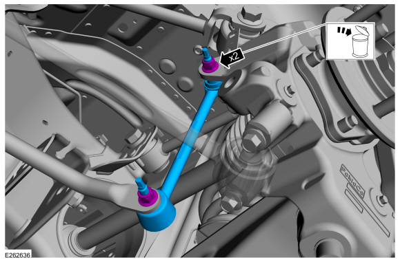
    Remove and discard the 2 rear stabilizer bar link nuts and remove the rear stabilizer bar link.
    Torque: 46 lb.ft (63 Nm)

    read more

    Copyright © 2025 www.linavigator4.com