Lincoln Navigator: Supplemental Restraint System / Side Airbag. Removal and Installation
Special Tool(s) / General Equipment
| Interior Trim Remover |
Removal
 WARNING:
The following procedure prescribes critical repair steps
required for correct restraint system operation during a crash. Follow
all notes and steps carefully. Failure to follow step instructions may
result in incorrect operation of the restraint system and increases the
risk of serious personal injury or death in a crash.
WARNING:
The following procedure prescribes critical repair steps
required for correct restraint system operation during a crash. Follow
all notes and steps carefully. Failure to follow step instructions may
result in incorrect operation of the restraint system and increases the
risk of serious personal injury or death in a crash.
NOTE: Removal steps in this procedure may contain installation details.
NOTE: RH (right-hand) seat shown, LH (left-hand) seat similar.
All seats
-
Refer to: Pyrotechnic Device Health and Safety Precautions (100-00 General Information, Description and Operation).
WARNING:
Before beginning any service procedure in this
manual, refer to health and safety warnings in section 100-00 General
Information. Failure to follow this instruction may result in serious
personal injury.
-
Remove the front seat.
Refer to: Front Seat (501-10A Front Seats, Removal and Installation).
-
Remove the video display.
Refer to: Information and Entertainment System - Component Location (415-00 Information and Entertainment System - General Information - Vehicles With: SYNC 4, Description and Operation).
-
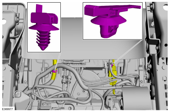
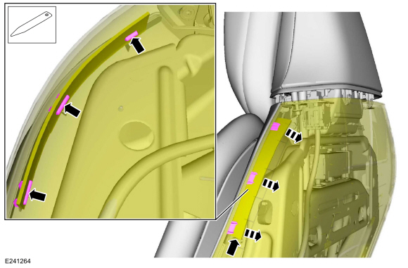
Release the front seat wiring harness and electrical
connector retainers and position the front seat wiring harnesses aside.
 |
-
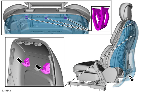
Detach the back panel straps from the seat track and position the back panel aside.
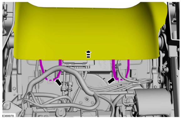 |
Seats with power head restraint
-
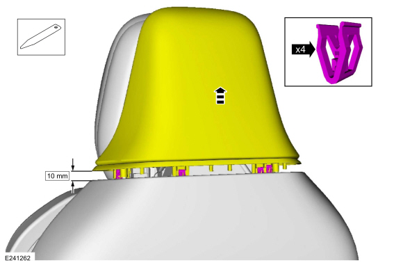
NOTICE: The back panel finish can be easily marred or torn, use care when working around it.
Raise and partially separate the head restraint rear cover enough to disengage the clips from the back panel.
Use the General Equipment: Interior Trim Remover
 |
All seats
-
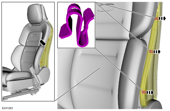
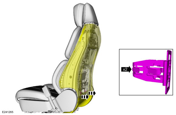
NOTE: The back panel finish can be easily marred or torn, use care when working around it.
On both sides.
Grasp the back panel where it meets the module trim, pull to release the clips and separate the back panel from the module trim.
 |
-
NOTE: The back panel finish can be easily marred or torn, use care when working around it.
On both sides.
Using the interior trim remover, place it in between the plastic substrate and the clip, pry and detach the module clips from the back panel windows.
Use the General Equipment: Interior Trim Remover
 |
-
Pull out at the bottom, release the clips and detach the back panel from the backrest frame.
 |
-
Pull out at the sides of the back panel.
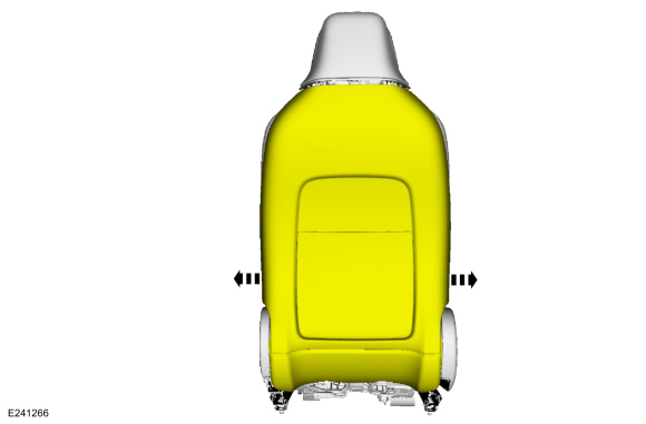 |
Seats with power head restraint
-
Pull down and out and remove the back panel.
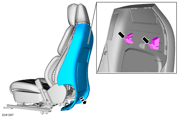 |
Seats with manual head restraint
-
Pull down and out and remove the back panel.
 |
All seats
-
NOTE: Follow the unique instructions or graphic for this step in the installation.
-
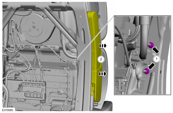
Remove the side airbag nuts.
Torque: 62 lb.in (7 Nm)
-
Detach the side airbag studs from the backrest frame.
-
Remove the side airbag nuts.
 |
-
Remove the side airbag.
-
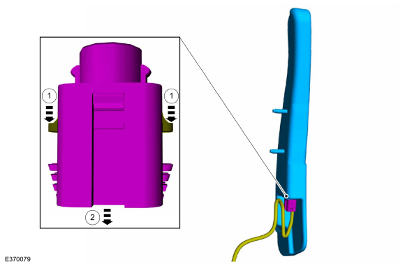
Release the side airbag electrical connector locking tabs.
-
Disconnect the side airbag electrical connector.
-
Release the side airbag electrical connector locking tabs.
 |
Installation
WARNING:
Incorrect repair techniques or actions can cause an
accidental Supplemental Restraint System deployment. Make sure the
restraint system is depowered before reconnecting the component. Refer
to the Supplemental Restraint System depowering General Procedure in
section 501-20B. Failure to precisely follow depowering instructions
could result in serious personal injury from an accidental deployment.
-
To install, reverse the removal procedure.
WARNING:
Inspect the seat side airbag, airbag cavity,
mounting surface and deployment chute for damage or the presence of
foreign material. Remove all foreign material. Install a new side airbag
if it is damaged. Install a new deployment chute if the deployment
chute is damaged. Failure to follow these instructions may result in the
seat side airbag deploying incorrectly and increase the risk of serious
personal injury or death in a crash.
 Side Curtain Airbag. Removal and Installation
Removal
WARNING:
The following procedure prescribes critical repair steps
required for correct restraint system operation during a crash...

Other information:
Lincoln Navigator 2018-2026 Workshop Manual: Rear Fender Splash Shield. Removal and Installation
Removal NOTE: Removal steps in this procedure may contain installation details. NOTE: LH side shown, RH side similar. All vehicles Remove the RH side rear wheel. Refer to: Wheel and Tire (204-04A Wheels and Tires, Removal and Installation). Long wheelbase Remove the nuts. Torque: 28 lb.in (3.2 Nm) ..
Lincoln Navigator 2018-2026 Workshop Manual: Front Seatbelt Retractor and Pretensioner. Removal and Installation
Removal WARNING: The following procedure prescribes critical repair steps required for correct restraint system operation during a crash. Follow all notes and steps carefully. Failure to follow step instructions may result in incorrect operation of the restraint system and increases the risk of serious personal injury or death in a crash. NOTE: Removal steps in this..
Categories
- Manuals Home
- 4th Gen Lincoln Navigator Service Manual (2018 - 2026)
- Head Up Display (HUD) Module Calibration. General Procedures
- Transmission Fluid Level Check. General Procedures
- All Terrain Control Module (ATCM). Removal and Installation
- Remote Function Actuator (RFA) Module. Removal and Installation
- Identification Codes. Description and Operation
Front Stabilizer Bar Link. Removal and Installation
Removal
NOTICE: Suspension fasteners are critical parts that affect the performance of vital components and systems. Failure of these fasteners may result in major service expense. Use the same or equivalent parts if replacement is necessary. Do not use a replacement part of lesser quality or substitute design. Tighten fasteners as specified.
NOTE: Removal steps in this procedure may contain installation details.
With the vehicle in NEUTRAL, position it on a hoist.Refer to: Jacking and Lifting (100-02 Jacking and Lifting, Description and Operation).
NOTICE: Do not use power tools to remove or install the stabilizer bar