Lincoln Navigator: Rear View Mirrors / Exterior Mirror. Removal and Installation
Special Tool(s) / General Equipment
| Flat Headed Screw Driver | |
| Interior Trim Remover |
Removal
Mirror assembly
-
Remove the interior front door trim panel.
Refer to: Front Door Trim Panel (501-05 Interior Trim and Ornamentation, Removal and Installation).
-
Disconnect the mirror wiring harness.
-
Disconnect the exterior mirror electrical connector.
-
If equipped.
Disconnect the camera electrical connector.
-
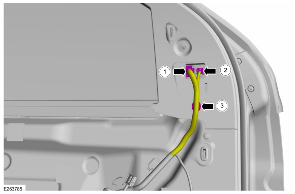
Separate the mirror harness retainer.
-
Disconnect the exterior mirror electrical connector.
 |
-
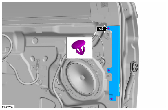
Remove the trim pins and the front door lower trim panel.
 |
-
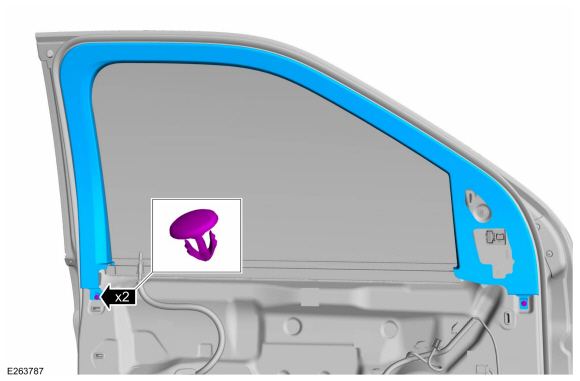
Remove the trim pins and the front door upper trim panel.
 |
-
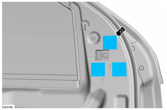
Remove the tape masks.
 |
-
NOTE: The mirror assembly has a molded hook for assembly aid at the factory. If the hook is damaged during mirror removal, remove the hook from the door panel and reuse the mirror.
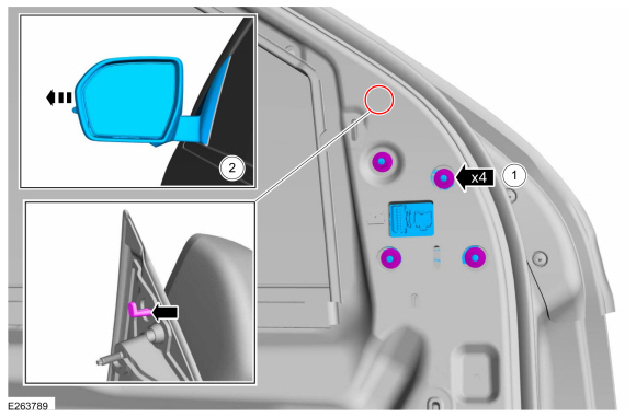
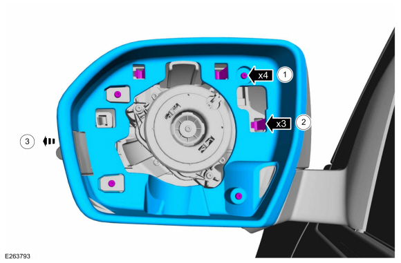
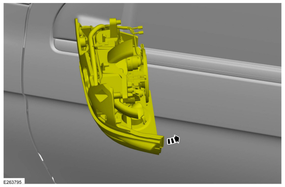
Remove the exterior mirror.
-
Remove the nuts.
Torque: 80 lb.in (9 Nm)
-
Slide the exterior mirror outward.
-
Remove the nuts.
 |
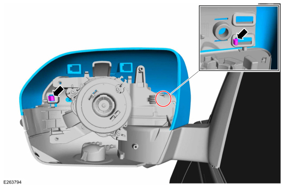
Exterior mirror glass
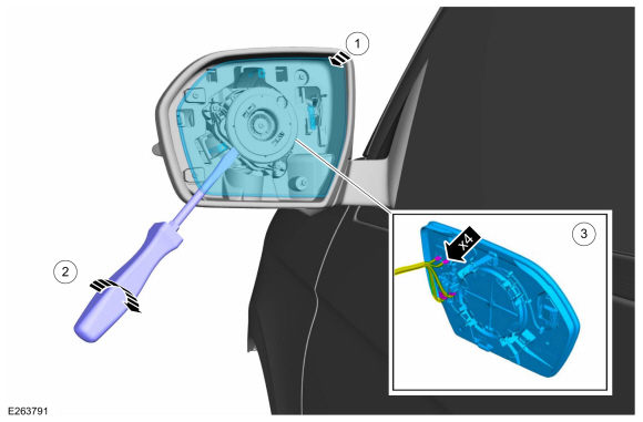
-
NOTICE: Position the screwdriver using the service slot in the mirror glass backing plate to remove the mirror glass. Prying on the backing plate in other locations may damage the mirror glass.
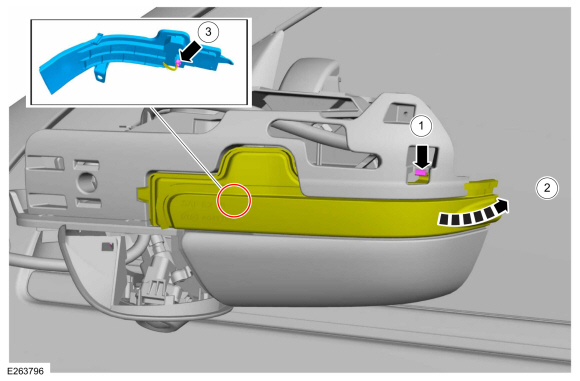
Remove the exterior mirror glass.
-
Position the mirror glass in and up.
-
Using a flat blade screwdriver separate the exterior mirror glass from the exterior mirror motor.
Use the General Equipment: Flat Headed Screw Driver
-
NOTE: The number and location of the electrical connectors will vary based on mirror option content.
Disconnect the exterior mirror glass electrical connectors.
-
Position the mirror glass in and up.
 |
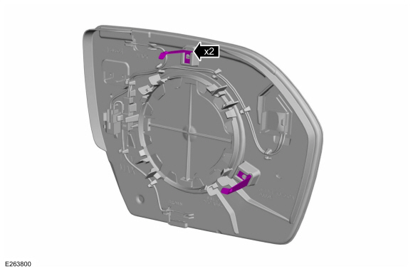
-
If required.
Install the new anti-vibration springs.
 |
Exterior mirror motor
-
Remove the exterior mirror glass.
-
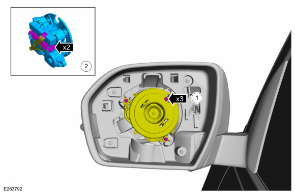
Remove the exterior mirror motor.
-
Remove the screws and position the exterior mirror motor aside.
-
Disconnect the exterior mirror motor electrical connectors.
-
Remove the screws and position the exterior mirror motor aside.
 |
Exterior mirror bezel
-
Remove the exterior mirror glass.
-
Remove the exterior mirror bezel.
-
Remove the exterior mirror bezel screws.
-
Release the exterior mirror bezel tabs.
-
Slide the exterior mirror bezel outward off the tabs.
-
Remove the exterior mirror bezel screws.
 |
Exterior mirror cover
-
Remove the exterior mirror bezel.
-
Release the exterior mirror cover tabs.
 |
-
Remove the exterior mirror cover.
 |
-
Release the tabs and remove the exterior mirror trim panel.
 |
Mirror mounted turn signal
-
Remove the exterior mirror cover.
-
Fold in the rear view mirror.
 |
-
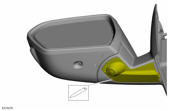
Remove the exterior mirror mounted turn signal.
-
Release the tab.
-
Position aside the exterior mirror mounted turn signal.
-
Disconnect the exterior mirror mounted turn signal electrical connector.
-
Release the tab.
 |
Puddle lamp
-
Remove the exterior mirror bezel.
-
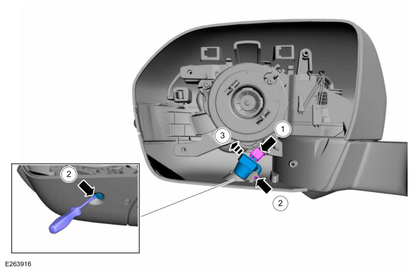
Remove the puddle lamp.
-
Disconnect the puddle lamp electrical connector.
-
Release the puddle lamp retaining lower and upper tabs.
Use the General Equipment: Flat Headed Screw Driver
-
Remove the puddle lamp.
-
Disconnect the puddle lamp electrical connector.
 |
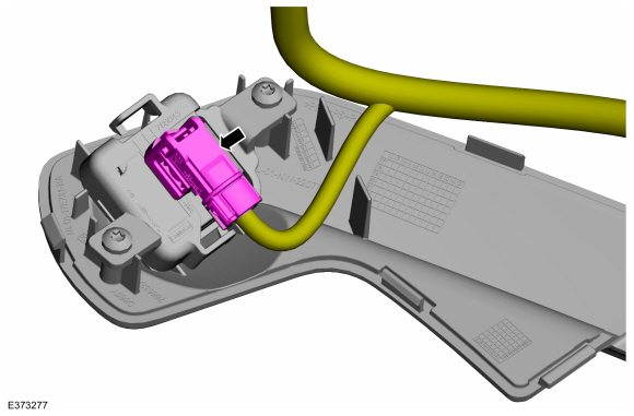
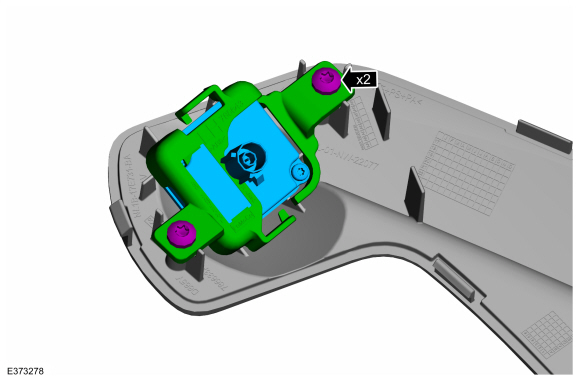
Parking camera
-
Using interior trim remover, release the tabs and position aside the camera cover.
Use the General Equipment: Interior Trim Remover
 |
-
Disconnect the electrical connector and position aside the wiring harness.
 |
-
Remove the screws, camera holding bracket and camera.
 |
Installation
Exterior mirror
-
To install, reverse the removal procedure.
Exterior mirror glass
-
To install, reverse the removal procedure.
Exterior mirror motor
-
To install, reverse the removal procedure.
Exterior mirror bezel
-
To install, reverse the removal procedure.
Exterior mirror cover
-
To install, reverse the removal procedure.
Exterior mirror mounted turn signal
-
To install, reverse the removal procedure.
-
On vehicles equipped with power fold mirrors synchronize the mirrors.
Refer to: Power Mirrors Synchronization (501-09 Rear View Mirrors, General Procedures).
Puddle lamp
-
To install, reverse the removal procedure.
All mirror components
-
To install, reverse the removal procedure.
NOTE: Carry out the following steps only if a mirror assembly or mirror cover was removed.
Vehicles equipped with 360° cameras only.
-
Align the 360° cameras.
Refer to: 360 Degree View Camera Alignment (413-13B Parking Aid - Vehicles With: Parking Aid Camera, General Procedures).
 Power Mirrors Synchronization. General Procedures
Synchronization
NOTE:
The power folding mirrors may need to be synchronized any
time the mirrors are folded or unfolded without using the folding
switch, or if a new power folding mirror is installed...
 Interior Rear View Mirror. Removal and Installation
Special Tool(s) /
General Equipment
Interior Trim Remover
Removal
NOTE:
Removal steps in this procedure may contain installation details...
Other information:
Lincoln Navigator 2018-2026 Workshop Manual: Specifications
General Specifications Item Specification Spark plug 12405 Spark plug gap 0.030 in ( .75 mm) ..
Lincoln Navigator 2018-2026 Workshop Manual: Front Suspension Height Sensor. Removal and Installation
Removal NOTE: Removal steps in this procedure may contain installation details. Remove the wheel and tire. Refer to: Wheel and Tire (204-04A Wheels and Tires, Removal and Installation). NOTE: Note the position of the components before removal. NOTE: LH height sensor assembly shown, RH similar. Disconnect the height sensor el..
Categories
- Manuals Home
- 4th Gen Lincoln Navigator Service Manual (2018 - 2026)
- Windshield Washer Pump. Removal and Installation
- SYNC Module [APIM]. Removal and Installation
- Neutral Flat Tow Activation and Deactivation. General Procedures
- Rear Bumper. Removal and Installation
- Front Bumper Cover. Removal and Installation
Rear Stabilizer Bar Link. Removal and Installation
Removal
NOTE: Removal steps in this procedure may contain installation details.
With the vehicle in NEUTRAL, position it on a hoist.Refer to: Jacking and Lifting (100-02 Jacking and Lifting, Description and Operation).
NOTE: Use the hex-holding feature to prevent the stud from turning while removing the nut.
Remove and discard the 2 rear stabilizer bar link nuts and remove the rear stabilizer bar link.Torque: 46 lb.ft (63 Nm)
