Lincoln Navigator: Fuel Charging and Controls - 3.5L EcoBoost (272kW/370PS) / Direct Injection Fuel Rail RH. Removal and Installation
Special Tool(s) / General Equipment
 |
303-1567 Sizer, Teflon Seal TKIT-2010C-FLM |
 |
307-005
(T59L-100-B)
Slide Hammer |
 |
310-205 Fuel Injector Brush |
 |
310-206 Remover, Fuel Injector TKIT-2009A-FLM |
 |
310-207 Installer, Fuel Injector Seal Assembly TKIT-2009A-FLM |
Removal
-
Remove the port injection fuel rail.
Refer to: Port Injection Fuel Rail (303-04A Fuel Charging and Controls - 3.5L EcoBoost (272kW/370PS), Removal and Installation).
-
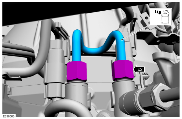
NOTICE: To release the fuel pressure in the high-pressure fuel tube, wrap the high-pressure fuel tube flare nuts with a shop towel to absorb any residual fuel pressure during the loosening of the flare nuts.
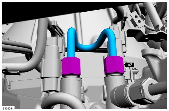
Disconnect the high-pressure fuel tube flare nuts, then remove and discard the high-pressure fuel tube.
 |
-
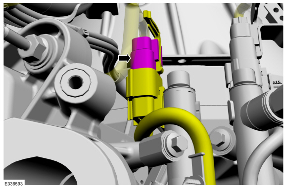
Disconnect the fuel injector main harness electrical connector.
 |
-
NOTICE: Pull out the fuel rails in the direction of the fuel injector axis or damage may occur to the fuel injectors.
-
Use compressed air to remove any dirt or foreign
material from the cylinder head, the engine block and the general
surrounding area of the fuel rail and the fuel injectors.
-
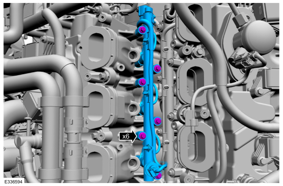
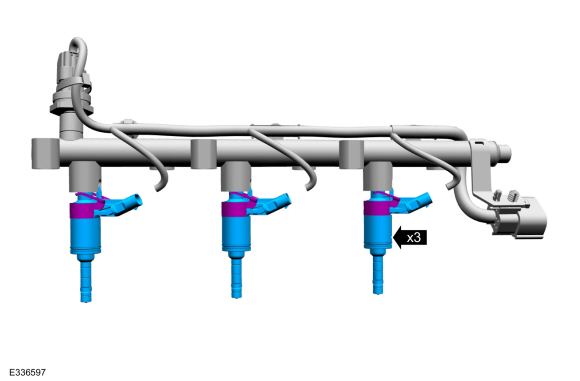
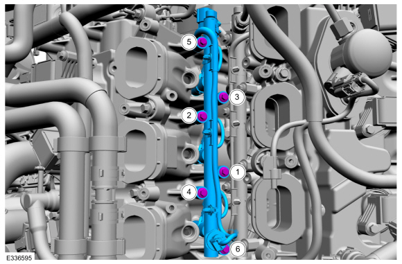
Remove the fuel rail bolts, then remove the fuel rail.
-
When removing the fuel rails, the fuel injectors may
remain in the cylinder heads and require the use of a Fuel Injector
Remover tool to extract. Wiggling the injector by hand to break it loose
may allow the injector to be removed by hand.
-
Use compressed air to remove any dirt or foreign
material from the cylinder head, the engine block and the general
surrounding area of the fuel rail and the fuel injectors.
 |
-
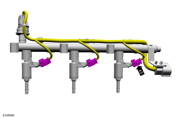
Disconnect the fuel injector electrical connectors
 |
-
Remove the fuel injectors from the fuel rail.
 |
-
Remove and discard the fuel injector clips.
 |
-
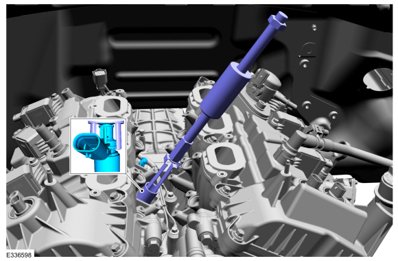
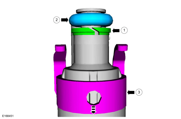
NOTICE: Use minimal force to remove the fuel injectors that remained in the cylinder head with the Fuel Injector Remover tool or damage to the fuel injector assembly may occur. Wiggling the injector by hand to break it loose may allow the injector to be removed by hand.
NOTE: Commercially available OTC 5028 8-1/2" long slide hammer may be substituted for 307-005 where there are clearance concerns.
Using the special tools, remove any of the fuel injectors that remained in the cylinder head.
Use Special Service Tool: 307-005 (T59L-100-B) Slide Hammer. , 310-206 Remover, Fuel Injector.
 |
-
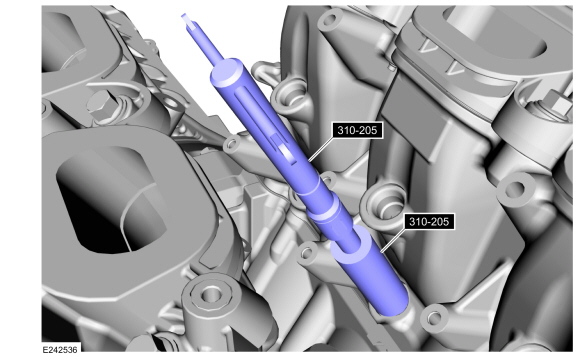
NOTICE: Do not use compressed air to clean the tip of the fuel injector.
NOTICE: Do not use a brush to clean the tip of the fuel injector.
-
NOTICE: Make sure to thoroughly clean any residual fuel or foreign material from the cylinder head, block and the general surrounding area of the fuel rails and injectors.
-
Using the special tool, clean the cylinder head fuel injector bores.
Use Special Service Tool: 310-205 Fuel Injector Brush.
-
 |
-
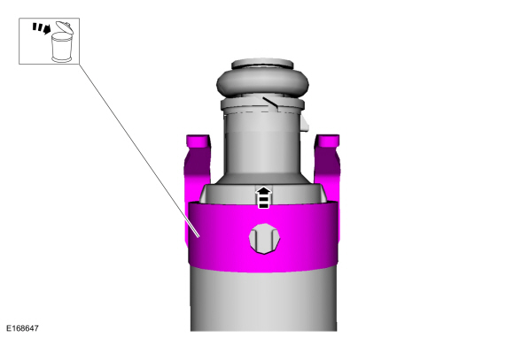
NOTE: Note the correct orientation of the fuel injector support rings, to insure the correct installation of the new fuel injector support rings.
-
Remove and discard the fuel injector O-rings.
-
Remove and discard the fuel injector support rings.
-
Remove and discard the fuel injector O-rings.
 |
-
NOTICE: Use care when removing the lower Teflon® seals, not to scratch, nick or gouge the fuel injector.
NOTICE: Do not attempt to cut the lower Teflon® seal without first pulling it away from the fuel injector or damage to the injector may occur.
-
Pull the lower Teflon® seal away from the injector.
-
Carefully cut and discard the lower fuel injector Teflon® seal.
-
Pull the lower Teflon® seal away from the injector.
 |
Installation
-
NOTICE: Do not lubricate the new lower Teflon® fuel injector seals.
-
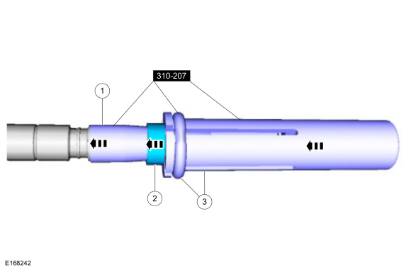
Install the Teflon® Seal Guide onto the fuel injector tip.
Use Special Service Tool: 310-207 Installer, Fuel Injector Seal Assembly.
-
NOTICE: Once the Teflon® seal is installed on the Teflon® Seal Guide, it should immediately be installed onto the fuel injector to avoid excessive expansion of the Teflon® seal.
NOTE: Make sure that new lower fuel injector Teflon® seals are installed.
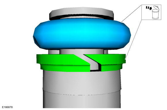
Install the new Teflon® seals onto the Teflon® Seal Guide, using the Pusher Tool, slide the Teflon® seals along the Teflon® Seal Guide.
-
Using the Pusher Tool, slide the Teflon® seals off
of the Teflon® Seal Guide and into the groove on the fuel injectors.
Use Special Service Tool: 310-207 Installer, Fuel Injector Seal Assembly.
-
Remove the special tools.
-
Install the Teflon® Seal Guide onto the fuel injector tip.
 |
-
NOTE: Make sure the Teflon® seal is fully seated in the groove on the fuel injector before sizing the Teflon® seal.
NOTE: The beveled opening of the Teflon® seal sizer tool goes away from the seal.
NOTE: Do not use the injector without re-forming the Teflon seal after replacing.
-
Use a soft brush to clean the inside of the re-forming tool before each use.
-
Massage and warm the Teflon® seal with your fingers
before the Teflon® seal sizer tool is installed. This will aid in
installing the Teflon® seal sizer tool.
-
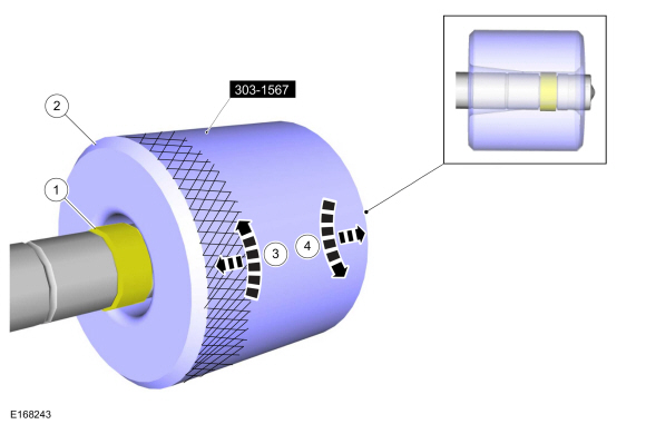
Position the Teflon® seal sizer tool with the larger
opening towards the Teflon® seal. Push while turning the Teflon® seal
sizer tool 180 degrees.
Use Special Service Tool: 303-1567 Sizer, Teflon Seal.
-
Once the Teflon® seal sizer tool is installed, check
and make sure the Teflon® seal is in the sizing portion of the Teflon®
seal sizer tool.
-
After one minute, turn the Teflon® seal sizer tool back 180 degrees and remove.
-
Use a soft brush to clean the inside of the re-forming tool before each use.
 |
-
NOTE: Make sure that new fuel injector support rings, new fuel injector O-ring seals and new fuel injector clips are installed.
-
NOTICE: The new the fuel injector support rings must be installed in the correct orientation with the wide surface area facing up against the fuel injector O-ring seals. Improperly installed support rings may cause the fuel system to leak.
Install the new the fuel injector support rings.
-
Install the new fuel injector O-ring seals.
-
Install the new the fuel injector clips.
-
 |
-
NOTICE: Do not re-use a fuel injector if it is dropped.
Install the fuel injectors to the fuel rail.
|
-
Connect the fuel injector electrical connectors.
|
-
NOTE: Do not lubricate the new lower Teflon® fuel injector seals.
Install the fuel rail, push down on the fuel rail above the injectors, then tighten the fuel rail bolts in the following 2 stages, in the sequence shown.
Torque:
Stage 1: Tighten to : 89 lb.in (10 Nm)
Stage 2: Tighten an additional : 45°
 |
-
Connect the fuel injector main harness electrical connector.
|
-
NOTICE: In stage 3, if the torque required to tighten any flare nut on the new high-pressure fuel tube reaches or exceeds 55 lb.ft (75 Nm), then that high pressure fuel tube must be discarded and replaced with another new high-pressure fuel tube.
NOTE: Make sure that a new fuel rail to fuel rail high-pressure fuel tube is installed.
NOTE: Calculate the correct torque wrench setting for the following torque using the Torque Wrench Adapter Formulas.
Install the fuel rail to fuel rail high-pressure fuel tube and tighten the flare nuts finger tight, then tighten the flare nuts in the following 3 stages.
Torque:
Stage 1: Tighten to : 62 lb.in (7 Nm)
Stage 2: Tighten to : 89 lb.in (10 Nm)
Stage 3: Tighten an additional : 30°
 |
-
Install the port injection fuel rail.
Refer to: Port Injection Fuel Rail (303-04A Fuel Charging and Controls - 3.5L EcoBoost (272kW/370PS), Removal and Installation).
 Direct Injection Fuel Rail LH. Removal and Installation
Special Tool(s) /
General Equipment
303-1567Sizer, Teflon SealTKIT-2010C-FLM
307-005
(T59L-100-B)
Slide Hammer
310-205Fuel Injector Brush
310-206Remover, Fuel InjectorTKIT-2009A-FLM
310-207Installer, Fuel Injector Seal AssemblyTKIT-2009A-FLM
Removal
Remove the direct injection fuel rail RH...
 Fuel Injectors. Removal and Installation
Removal and Installation
The fuel injectors are removed with the fuel rails.
Refer to: Direct Injection Fuel Rail LH (303-04A Fuel Charging and
Controls - 3...
Other information:
Lincoln Navigator 2018-2026 Workshop Manual: Oil Cooler. Removal and Installation
Special Tool(s) / General Equipment Oil Drain Equipment Hose Clamp Remover/Installer Locking Pliers Removal With the vehicle in NEUTRAL, position it on a hoist. Refer to: Jacking and Lifting (100-02 Jacking and Lifting, Description and Operation)...
Lincoln Navigator 2018-2026 Workshop Manual: Tire Pressure Monitoring System (TPMS) Sensor. Removal and Installation
Removal WARNING: The Tire Pressure Monitoring System (TPMS) sensor battery may release hazardous chemicals if exposed to extreme mechanical damage. If these chemicals contact the skin or eyes, flush immediately with water for a minimum of 15 minutes and get prompt medical attention...
Categories
- Manuals Home
- 4th Gen Lincoln Navigator Service Manual (2018 - 2026)
- Power Running Board (PRB). Diagnosis and Testing
- Transmission Fluid Drain and Refill. General Procedures
- Rear Bumper. Removal and Installation
- All Terrain Control Module (ATCM). Removal and Installation
- Brake Service Mode Activation and Deactivation. General Procedures
Wheel to Hub Runout Minimization. General Procedures
Check
NOTE: Wheel-to-hub optimization is important. Clearance between the wheel and hub can be used to offset or neutralize the Road Force® or run-out of the wheel and tire assembly. For every 0.001 inch of wheel-to-hub clearance, the Road Force® can be affected between 1 and 3 pounds depending on the tire stiffness.
NOTE: The example below illustrates how the clearance between the wheel and the hub can be used to offset the high spot of radial run-out or Road Force®. Following the procedure will make sure of the best optimization.
Position the wheel and tire assembly on the vehicle so that the high spot location of radial run-out or Road Force® is at the 6 o'clock position and