Lincoln Navigator: Fuel Charging and Controls - 3.5L EcoBoost (272kW/370PS) / Direct Injection Fuel Rail LH. Removal and Installation
Special Tool(s) / General Equipment
 |
303-1567 Sizer, Teflon Seal TKIT-2010C-FLM |
 |
307-005
(T59L-100-B)
Slide Hammer |
 |
310-205 Fuel Injector Brush |
 |
310-206 Remover, Fuel Injector TKIT-2009A-FLM |
 |
310-207 Installer, Fuel Injector Seal Assembly TKIT-2009A-FLM |
Removal
-
Remove the direct injection fuel rail RH.
Refer to: Direct Injection Fuel Rail RH (303-04A Fuel Charging and Controls - 3.5L EcoBoost (272kW/370PS), Removal and Installation).
-
Disconnect the fuel injector main harness electrical connector.
 |
-
-
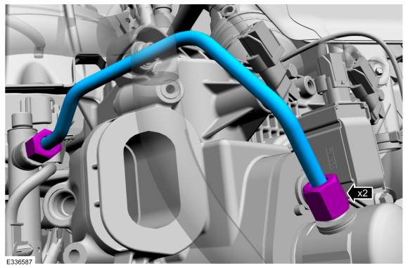
NOTICE: To release the fuel pressure in the high-pressure fuel tube, wrap the flare nuts with a shop towel to absorb any residual fuel pressure during the loosening the flare nuts.
-
Disconnect the flare nuts, then remove and discard the high-pressure fuel tube.
-
 |
-
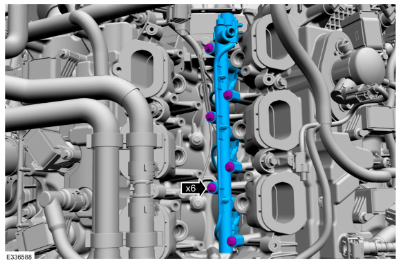
NOTICE: Pull out the fuel rails in the direction of the fuel injector axis or damage may occur to the fuel injectors.
-
Use compressed air to remove any dirt or foreign
material from the cylinder head, the engine block and the general
surrounding area of the fuel rail and the fuel injectors.
-
Remove the fuel rail bolts, then remove the fuel rail.
-
When removing the fuel rails, the fuel injectors may
remain in the cylinder heads and require the use of a Fuel Injector
Remover tool to extract. Wiggling the injector by hand to break it loose
may allow the injector to be removed by hand.
-
Use compressed air to remove any dirt or foreign
material from the cylinder head, the engine block and the general
surrounding area of the fuel rail and the fuel injectors.
 |
-
Disconnect the fuel injector electrical connectors
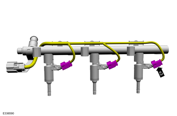 |
-
Remove the fuel injectors from the fuel rail.
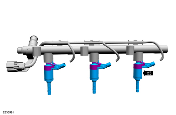 |
-
Remove and discard the fuel injector clips.
 |
-
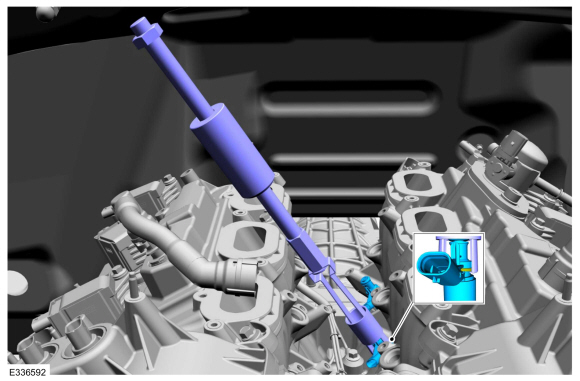
NOTICE: Use minimal force to remove the fuel injectors that remained in the cylinder head with the Fuel Injector Remover tool or damage to the fuel injector assembly may occur. Wiggling the injector by hand to break it loose may allow the injector to be removed by hand.
NOTE: Commercially available OTC 5028 8-1/2" long slide hammer may be substituted for 307-005 where there are clearance concerns.
Using the special tools, remove any of the fuel injectors that remained in the cylinder head.
Use Special Service Tool: 307-005 (T59L-100-B) Slide Hammer. , 310-206 Remover, Fuel Injector.
 |
-
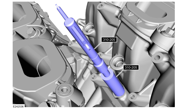
NOTICE: Do not use compressed air to clean the tip of the fuel injector.
NOTICE: Do not use a brush to clean the tip of the fuel injector.
-
NOTICE: Make sure to thoroughly clean any residual fuel or foreign material from the cylinder head, block and the general surrounding area of the fuel rails and injectors.
-
Using the special tool, clean the cylinder head fuel injector bores.
Use Special Service Tool: 310-205 Fuel Injector Brush.
-
 |
-
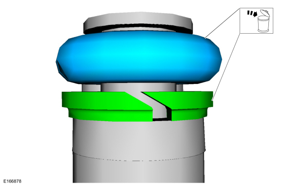
NOTE: Note the correct orientation of the fuel injector support rings, to insure the correct installation of the new fuel injector support rings.
-
Remove and discard the fuel injector O-rings.
-
Remove and discard the fuel injector support rings.
-
Remove and discard the fuel injector O-rings.
 |
-
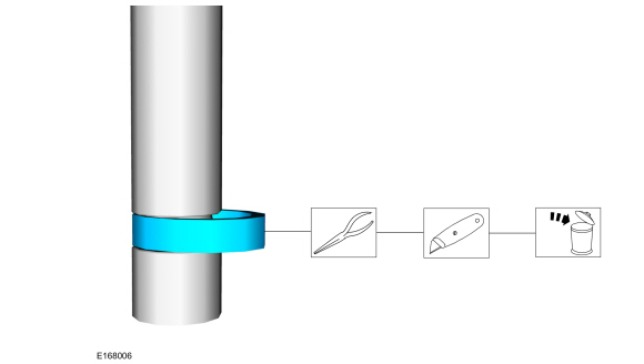
NOTICE: Use care when removing the lower Teflon® seals, not to scratch, nick or gouge the fuel injector.
NOTICE: Do not attempt to cut the lower Teflon® seal without first pulling it away from the fuel injector or damage to the injector may occur.
-
Pull the lower Teflon® seal away from the injector.
-
Carefully cut and discard the lower fuel injector Teflon® seal.
-
Pull the lower Teflon® seal away from the injector.
 |
Installation
-
NOTICE: Do not lubricate the new lower Teflon® fuel injector seals.
-
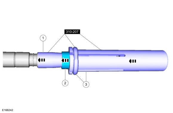
Install the Teflon® Seal Guide onto the fuel injector tip.
Use Special Service Tool: 310-207 Installer, Fuel Injector Seal Assembly.
-
NOTICE: Once the Teflon® seal is installed on the Teflon® Seal Guide, it should immediately be installed onto the fuel injector to avoid excessive expansion of the Teflon® seal.
NOTE: Make sure that new lower fuel injector Teflon® seals are installed.
Install the new Teflon® seals onto the Teflon® Seal Guide, using the Pusher Tool, slide the Teflon® seals along the Teflon® Seal Guide.
-
Using the Pusher Tool, slide the Teflon® seals off
of the Teflon® Seal Guide and into the groove on the fuel injectors.
Use Special Service Tool: 310-207 Installer, Fuel Injector Seal Assembly.
-
Remove the special tools.
-
Install the Teflon® Seal Guide onto the fuel injector tip.
 |
-
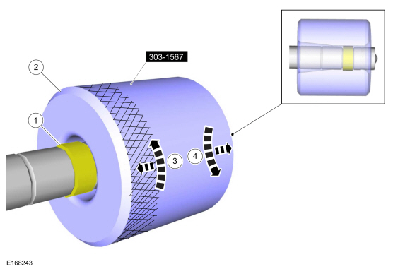
NOTE: Make sure the Teflon® seal is fully seated in the groove on the fuel injector before sizing the Teflon® seal.
NOTE: The beveled opening of the Teflon® seal sizer tool goes away from the seal.
NOTE: Do not use the injector without re-forming the Teflon seal after replacing.
-
Use a soft brush to clean the inside of the re-forming tool before each use.
-
Massage and warm the Teflon® seal with your fingers
before the Teflon® seal sizer tool is installed. This will aid in
installing the Teflon® seal sizer tool.
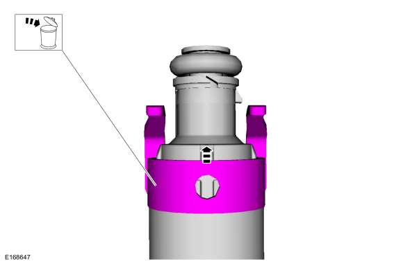
-
Position the Teflon® seal sizer tool with the larger
opening towards the Teflon® seal. Push while turning the Teflon® seal
sizer tool 180 degrees.
Use Special Service Tool: 303-1567 Sizer, Teflon Seal.
-
Once the Teflon® seal sizer tool is installed, check
and make sure the Teflon® seal is in the sizing portion of the Teflon®
seal sizer tool.
-
After one minute, turn the Teflon® seal sizer tool back 180 degrees and remove.
-
Use a soft brush to clean the inside of the re-forming tool before each use.
 |
-
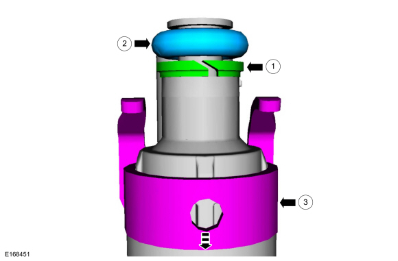
NOTE: Make sure that new fuel injector support rings and new fuel injector O-ring seals are installed.
-
NOTICE: The new the fuel injector support rings must be installed in the correct orientation with the wide surface area facing up against the fuel injector O-ring seals. Improperly installed support rings may cause the fuel system to leak.
Install the new the fuel injector support rings.
-
Install the new fuel injector O-ring seals.
-
Install the new the fuel injector clips.
-
 |
-
NOTICE: Do not re-use a fuel injector if it is dropped.
Install the fuel injectors to the fuel rail.
|
-
Connect the fuel injector electrical connectors.
|
-
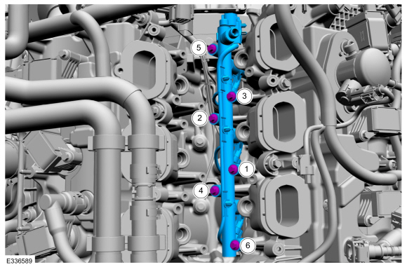
NOTE: Do not lubricate the new lower Teflon® fuel injector seals.
Install the fuel rail, push down on the fuel rail above the injectors, then tighten the fuel rail bolts in the following 2 stages, in the sequence shown.
Torque:
Stage 1: Tighten to : 89 lb.in (10 Nm)
Stage 2: Tighten an additional : 45°
 |
-
-
Calculate the correct torque wrench setting for the
following torque using the Torque Wrench Adapter Formulas.
-
NOTE: Make sure that a new high-pressure fuel tube is installed.
Install the high-pressure fuel tube and tighten the flare nuts finger tight.
-
NOTICE: In stage 3, if the torque required to tighten any flare nut on the new high-pressure fuel tube reaches or exceeds 55 lb.ft (75 Nm), then that high pressure fuel tube must be discarded and replaced with another new high-pressure fuel tube.
Tighten the high-pressure fuel tube flare nuts, in the following 3 stages.
Torque:
Stage 1: Tighten to : 80 lb.in (9 Nm)
Stage 2: Tighten to : 89 lb.in (10 Nm)
Stage 3: Tighten an additional : 38°
-
Calculate the correct torque wrench setting for the
following torque using the Torque Wrench Adapter Formulas.
 |
-
Connect the fuel injector main harness electrical connector.
|
-
Install the direct injection fuel rail RH.
Refer to: Direct Injection Fuel Rail RH (303-04A Fuel Charging and Controls - 3.5L EcoBoost (272kW/370PS), Removal and Installation).
 High-Pressure Fuel System. Diagnosis and Testing
Diagnostic Trouble Code (DTC) Chart
Diagnostics in this manual assume a certain skill level and knowledge of Ford-specific diagnostic practices. REFER to: Diagnostic Methods (100-00 General Information, Description and Operation)...
 Direct Injection Fuel Rail RH. Removal and Installation
Special Tool(s) /
General Equipment
303-1567Sizer, Teflon SealTKIT-2010C-FLM
307-005
(T59L-100-B)
Slide Hammer
310-205Fuel Injector Brush
310-206Remover, Fuel InjectorTKIT-2009A-FLM
310-207Installer, Fuel Injector Seal AssemblyTKIT-2009A-FLM
Removal
Remove the port injection fuel rail...
Other information:
Lincoln Navigator 2018-2026 Workshop Manual: Charge Air Cooler (CAC) Intake Pipe. Removal and Installation
Removal NOTICE: The turbocharger compressor vanes can be damaged by even the smallest particles. When removing any turbocharger or engine air intake system component, ensure that no debris enters the system. Failure to do so may result in damage to the turbocharger...
Lincoln Navigator 2018-2026 Workshop Manual: Engine. Diagnosis and Testing
Symptom Charts Symptom Chart - Gasoline Engine Performance Diagnostics in this manual assume a certain skill level and knowledge of Ford-specific diagnostic practices. REFER to: Diagnostic Methods (100-00 General Information, Description and Operation)...
Categories
- Manuals Home
- 4th Gen Lincoln Navigator Service Manual (2018 - 2026)
- Brake Service Mode Activation and Deactivation. General Procedures
- Liftgate Trim Panel. Removal and Installation
- Neutral Flat Tow Activation and Deactivation. General Procedures
- Power Running Board (PRB). Diagnosis and Testing
- Rear Bumper. Removal and Installation
Rear Drive Axle and Differential. Diagnosis and Testing
Symptom Chart(s)
Diagnostics in this manual assume a certain skill level and knowledge of Ford-specific diagnostic practices.
REFER to: Diagnostic Methods (100-00 General Information, Description and Operation).
Symptom Chart - Differential
Symptom Chart - Differential
Condition Actions Axle overheating GO to Pinpoint Test A Broken gear teeth on the ring gear or pinion GO to Pi