Lincoln Navigator: Front Drive Axle/Differential / Differential Housing Cover. Removal and Installation
Materials
| Name |
Specification |
Motorcraft® Ultra Silicone Sealant
TA-29 |
WSS-M4G323-A8
|
Removal
-
With the vehicle in NEUTRAL, position it on a hoist.
Refer to: Jacking and Lifting (100-02 Jacking and Lifting, Description and Operation).
-
If equipped.
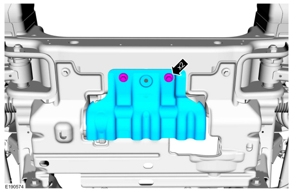
Remove the bolts and the spacer from the front underbody skid plate.
-
If equipped.
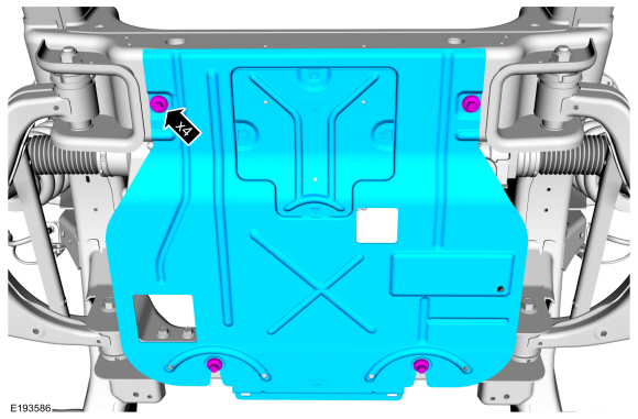
Remove the bolts and the front underbody skid plate.
-
If equipped.
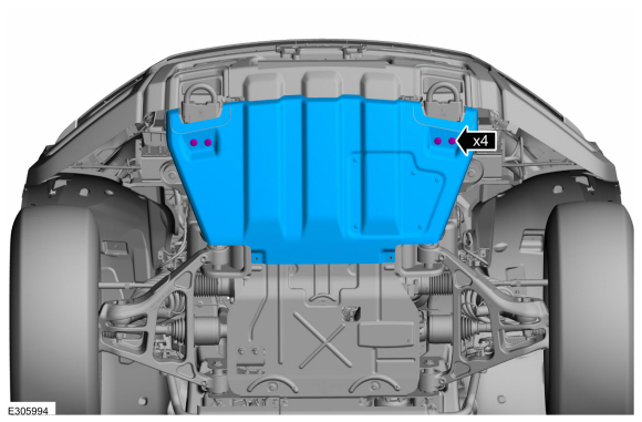
Remove the bolts and the engine skid plate.
-
If equipped.
Remove the bolts and the skid plate.
-
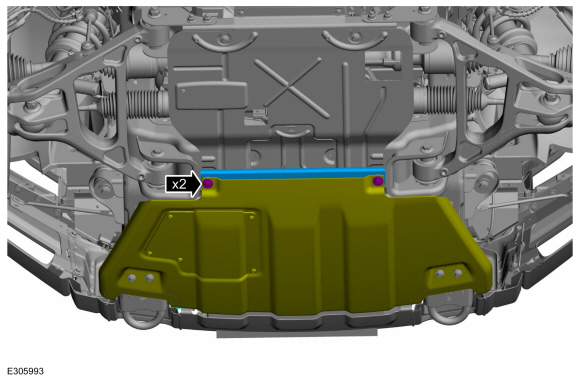
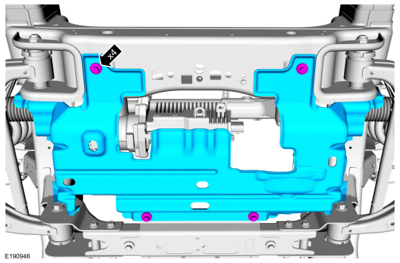
Remove the bolts and the engine oil pan skid plate.
-
If equipped.
Remove bolts and the oil drip tray from the cross member.
-
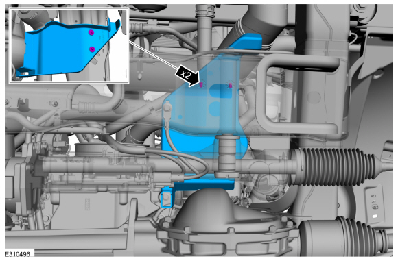
If equipped.
-
Remove and discard the push pins.
-
Remove the steering gear shield from the frame rail.
-
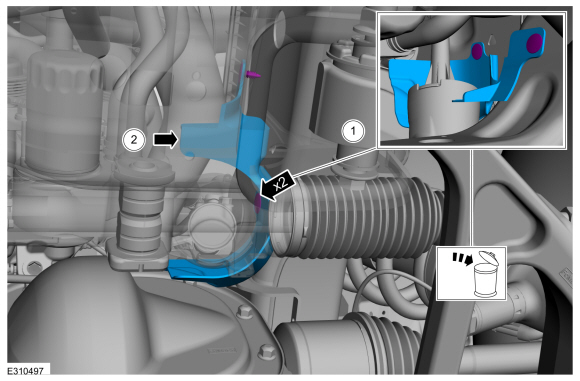
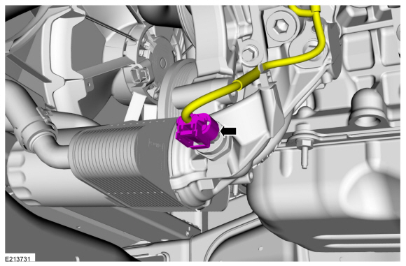
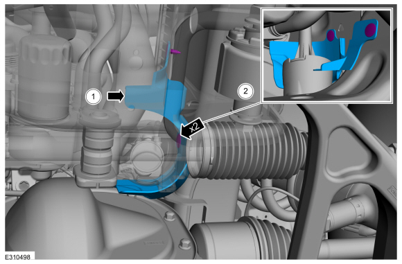
Disconnect the front differential breather hose and position aside.
-
If equipped.
Disconnect the EOP sensor electrical connector.
-
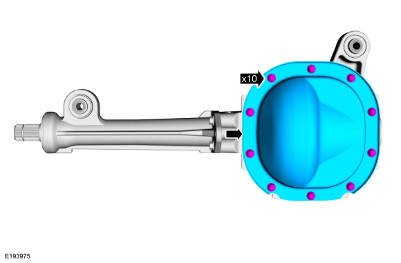
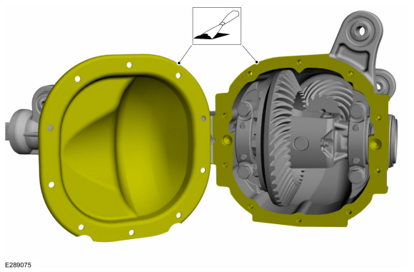
Remove the differential cover bolts and differential cover.
Installation
-
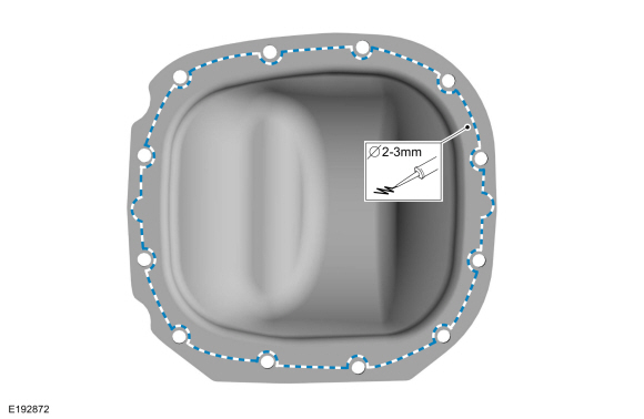
NOTE:
Remove all of the silicone gasket and make sure the
surfaces are free of oil before applying the new silicone gasket.
Clean the gasket mating surface of the axle and the differential housing cover.
-
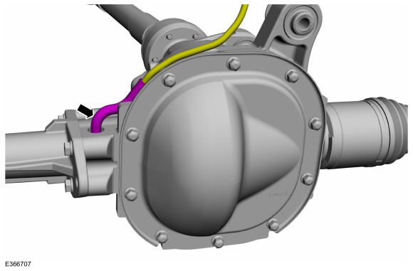
NOTE:
The differential housing cover must be installed
within 15 minutes of application of the silicone, or new sealant must be
applied. If possible, allow one hour before filling with lubricant to
make sure the silicone sealant has correctly cured.
Apply a new continuous bead of sealant to the differential housing cover as shown.
Material: Motorcraft® Ultra Silicone Sealant
/ TA-29
(WSS-M4G323-A8)
-
Install the differential housing cover and the bolts.
Torque:
24 lb.ft (32 Nm)
-
If equipped.
Connect the EOP sensor electrical connector.
-
If equipped.
-
Install the steering gear shield to the frame rail.
-
Install the new push pins.
-
If equipped.
Install the oil drip tray to the cross member and the bolts.
Torque:
62 lb.in (7 Nm)
-
Connect the front differential breather hose.
-
Install the engine oil pan skid plate and the bolts.
Torque:
30 lb.ft (40 Nm)
-
If equipped.
Install the skid plate and the bolts.
Torque:
30 lb.ft (40 Nm)
-
If removed.
Install the engine skid plate and the bolts.
Torque:
30 lb.ft (40 Nm)
-
If equipped.
Install the front underbody skid plate and the bolts.
Torque:
35 lb.ft (48 Nm)
-
If equipped.
Install the spacer to the front underbody skid plate and the bolts.
Torque:
41 lb.ft (55 Nm)
-
Fill the front differential assembly with clean fluid.
Refer to: Differential Fluid Level Check (205-03 Front Drive Axle/Differential, General Procedures).
Special Tool(s) /
General Equipment
100-002
(TOOL-4201-C)
Holding Fixture with Dial Indicator Gauge
205-001
(TOOL-4000-E)
Spreader, Differential Carrier
205-005
(T53T-4621-C)
Installer, Drive Pinion Bearing Cone
205-010
(T57L-4221-A2)
Installer, Differential Side Bearing
205-024
(T67P-4616-A)
Installer, Drive Pinion Bearin..
Other information:
Removal
Remove the front bumper cover.
Refer to: Front Bumper Cover (501-19 Bumpers, Removal and Installation).
Remove the screws and the bracket.
Remove the front parking aid camera and washer nozzle as an assembly.
If equipped.
Remove the front parking aid cam..
Special Tool(s) /
General Equipment
Grinder
MIG/MAG Welding Equipment
Locking Pliers
Removal
WARNING:
Frame rail crush zones absorb crash energy during a
collision and must be replaced if damaged. Prior to replacement of frame
rail crush zones, straighten damaged frame rails to correct frame
dimensions. Failure to follow these instructions m..

 Differential Ring Gear and Pinion. Removal and Installation