Lincoln Navigator: Climate Control System - General Information / Climate Control Housing. Removal and Installation
Removal
NOTICE: During the removal or installation of components, cap, tape or otherwise appropriately protect all openings and tubes/fittings to prevent the ingress of dirt or other contamination. Remove caps, tape and other protective materials prior to installation.
NOTE: Removal steps in this procedure may contain installation details.
-
Recover the refrigerant. Refer to the appropriate Recovery procedure in Group 412.
-
Depower the SRS .
Refer to: Supplemental Restraint System (SRS) Depowering (501-20B Supplemental Restraint System, General Procedures).
-
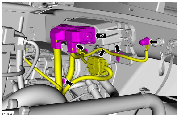
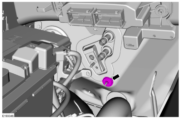
Disconnect the PCM
electrical connectors and detach the 4 wiring harness retainers.
Remove the nut and the ground wiring harness and position aside the
wiring harness.
Torque: 106 lb.in (12 Nm)
 |
-
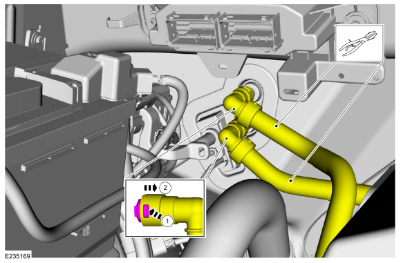
Clamp and disconnect the heater hoses.
 |
-
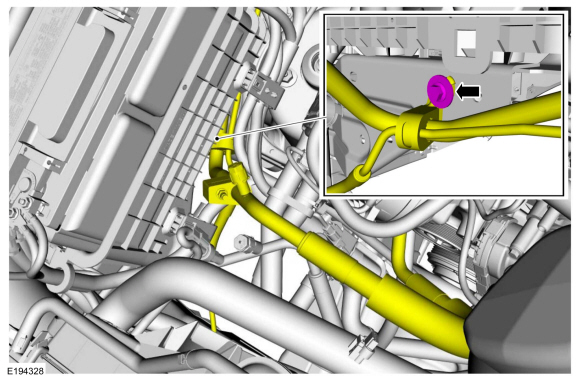
Remove the thermostatic expansion valve manifold tube assembly bracket retainer.
Torque: 133 lb.in (15 Nm)
 |
-
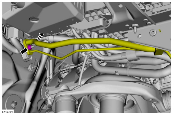
Remove the thermostatic expansion valve manifold and tube assembly nut, position the thermostatic expansion valve manifold and tube assembly aside.
-
Make sure to cover any open ports to prevent debris from entering the system.
Torque: 80 lb.in (9 Nm)
-
Make sure to cover any open ports to prevent debris from entering the system.
 |
-
Remove the nut and washer.
Torque: 62 lb.in (7 Nm)
 |
-
Remove the instrument panel.
Refer to: Instrument Panel (501-12 Instrument Panel and Console, Removal and Installation).
-
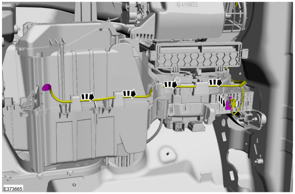
Detach and position aside the antenna cable wire harnesses.
 |
-
-
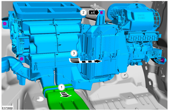
Remove the floor duct.
-
Remove the retainers.
Torque: 62 lb.in (7 Nm)
-
Remove the climate control housing.
-
Remove the floor duct.
 |
Installation
-
To install, reverse the removal procedure.
-
NOTICE: Only use the specified material to lubricate the seals.
Install and lubricate new O-ring seals. Refer to the appropriate Specifications in Group 412.
-
Lubricate the refrigerant system with the correct amount
of clean PAG oil. Refer to the appropriate Refrigerant Oil Adding
procedure in Group 412.
-
Repower the SRS .
Refer to: Supplemental Restraint System (SRS) Repowering (501-20B Supplemental Restraint System, General Procedures).
-
Fill and bleed the cooling system. Refer to filling and bleeding without a vacuum cooling system filler.
Refer to: Engine Cooling System Draining, Vacuum Filling and Bleeding (303-03 Engine Cooling - 3.5L EcoBoost (272kW/370PS), General Procedures).
 Center Registers. Removal and Installation
Special Tool(s) /
General Equipment
Interior Trim Remover
Removal
NOTE:
Removal steps in this procedure may contain installation details...
 Condenser. Removal and Installation
Removal
NOTICE:
During the removal of components, cap, tape or otherwise
appropriately protect all openings to prevent the ingress of dirt or
other contamination...
Other information:
Lincoln Navigator 2018-2026 Workshop Manual: Crankshaft Position (CKP) Sensor. Removal and Installation
Removal NOTE: Removal steps in this procedure may contain installation details. Remove the LH turbocharger. Refer to: Turbocharger LH (303-04B Fuel Charging and Controls - Turbocharger - 3.5L EcoBoost (272kW/370PS), Removal and Installation)...
Lincoln Navigator 2018-2026 Workshop Manual: Liftgate Release Switch. Removal and Installation
Removal Remove the reversing lamp assembly. Refer to: Reversing Lamp (417-01 Exterior Lighting, Removal and Installation). Disconnect the coaxial cable connector. Remove the screws and the bracket...
Categories
- Manuals Home
- 4th Gen Lincoln Navigator Service Manual (2018 - 2026)
- All Terrain Control Module (ATCM). Removal and Installation
- Transmission Fluid Level Check. General Procedures
- Liftgate Trim Panel. Removal and Installation
- Remote Function Actuator (RFA) Module. Removal and Installation
- Identification Codes. Description and Operation
Axle Tube Bearing. Removal and Installation
Special Tool(s) / General Equipment
 205-123
(T78P-1177-A)
205-123
(T78P-1177-A)
Installer, Axle Shaft Oil Seal
 308-047
(T77F-1102-A)
308-047
(T77F-1102-A)
Remover, Bearing Cup Slide Hammer