Lincoln Navigator: Climate Control System - General Information / Condenser. Removal and Installation
Removal
NOTICE: During the removal of components, cap, tape or otherwise appropriately protect all openings to prevent the ingress of dirt or other contamination. Remove protective materials prior to installation.
NOTE: Removal steps in this procedure may contain installation details.
NOTE: Expedition shown, Navigator similar.
-
Recover the refrigerant. Refer to the appropriate Recovery procedure in Group 412.
-
With the vehicle in N , position it on a hoist.
Refer to: Jacking and Lifting (100-02 Jacking and Lifting, Description and Operation).
-
-
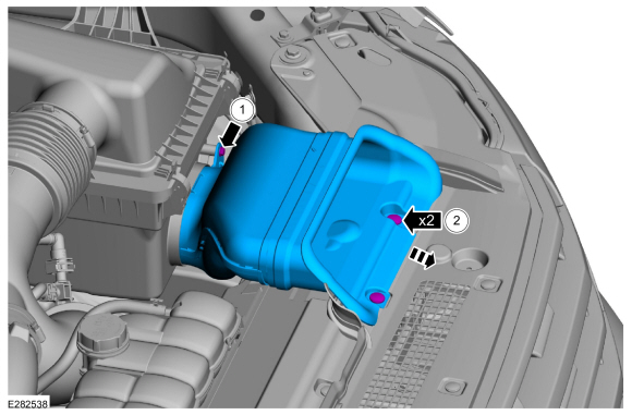
Remove the retainer.
-
Remove the push pin retainers and the air intake.
-
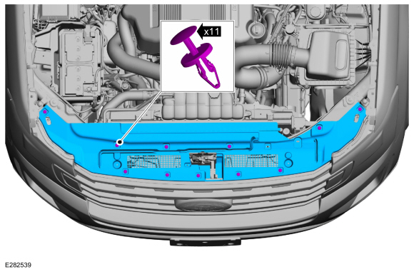
Remove the retainer.
 |
-
Remove the push pin retainers and the air deflector.
 |
-
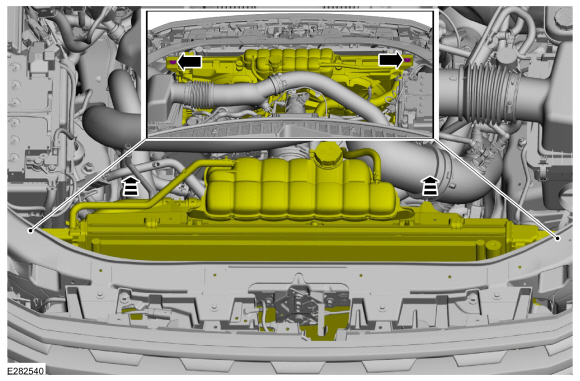
Remove the retainers and tilt the cooling module.
Torque: 133 lb.in (15 Nm)
 |
-
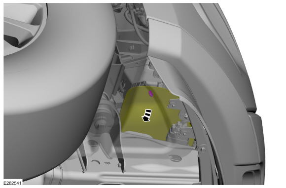
Position the lower air deflector aside.
 |
-
-
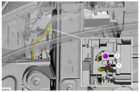
Remove the nut and disconnect the thermostatic expansion valve manifold and tube assembly.
Torque: 89 lb.in (10 Nm)
-
Remove the retainer.
Torque: 89 lb.in (10 Nm)
-
Make sure to cover any open ports to prevent debris from entering the system.
-
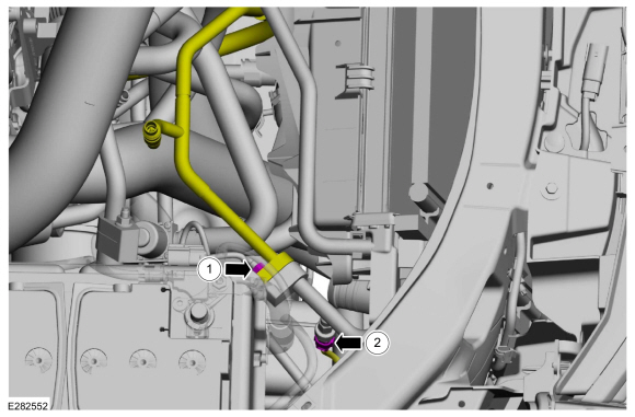
Remove the nut and disconnect the thermostatic expansion valve manifold and tube assembly.
 |
-
-
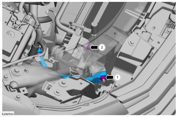
Remove the nut and disconnect the A/C fitting.
Torque: 159 lb.in (18 Nm)
-
Disconnect the electrical connector from the A/C pressure transducer.
-
Make sure to cover any open ports to prevent debris from entering the system.
-
Remove the nut and disconnect the A/C fitting.
 |
-
-
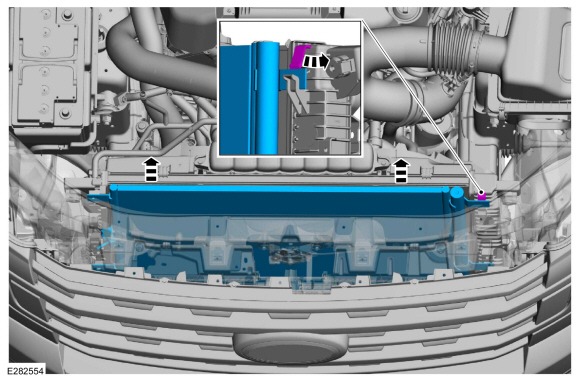
Remove the nut and the A/C compressor outlet line.
Torque: 159 lb.in (18 Nm)
-
Remove the retainer.
Torque: 89 lb.in (10 Nm)
-
Make sure to cover any open ports to prevent debris from entering the system.
-
Remove the nut and the A/C compressor outlet line.
 |
-
Release the tab and remove the condenser.
 |
Installation
-
To install, reverse the removal procedure.
-
NOTICE: Only use the specified material to lubricate the seals.
Install and lubricate new O-ring seals. Refer to the appropriate Specifications in Group 412.
-
Lubricate the refrigerant system with the correct amount
of clean PAG oil. Refer to the appropriate Refrigerant Oil Adding
procedure in Group 412.
 Climate Control Housing. Removal and Installation
Removal
NOTICE:
During the removal or installation of components, cap, tape
or otherwise appropriately protect all openings and tubes/fittings to
prevent the ingress of dirt or other contamination...
 Desiccant Bag. Removal and Installation
Removal
NOTICE:
During the removal or installation of components, cap, tape
or otherwise appropriately protect all openings and tubes/fittings to
prevent the ingress of dirt or other contamination...
Other information:
Lincoln Navigator 2018-2026 Workshop Manual: Perimeter Anti-Theft Alarm - System Operation and Component Description. Description and Operation
System Operation System Diagram Item Description 1 BCM 2 DDM 3 DRDM 4 GWM 5 DLC 6 IPC 7 PDM 8 PRDM 9 Front Passenger Door Lock Control Switch 10 RKE Antenna 11 Passive Key 12 RKE And Passive E..
Lincoln Navigator 2018-2026 Workshop Manual: Bezel Diagnostics. General Procedures
Check NOTE: If there is a concern with one of the following components and Bezel Diagnostics cannot be accessed, obtain the module part number by referencing the label attached to the module. Inoperative ACM Inoperative (blank or does not power on) display unit (non-touchscreen display or touchscreen display) Inoperative radio control panel Inoperative ..
Categories
- Manuals Home
- 4th Gen Lincoln Navigator Service Manual (2018 - 2026)
- Rear Bumper. Removal and Installation
- Remote Function Actuator (RFA) Module. Removal and Installation
- Head Up Display (HUD) Module Calibration. General Procedures
- SYNC Module [APIM]. Removal and Installation
- Body Control Module (BCM). Removal and Installation
Front Driveshaft. Removal and Installation
Special Tool(s) / General Equipment
Crimping ToolMaterials
Name Specification Motorcraft® Premium Long-Life GreaseXG-1-E1 ESA-M1C75-B
Removal
With the vehicle in NEUTRAL, position the vehicle on a hoist.Refer to: Jacking and Lifting (100-02 Jacking and Lifting, Description and Operation).
Remove the bolts and the transmission shield.