
Lincoln Navigator: Climate Control System - General Information / Desiccant Bag. Removal and Installation
Removal
NOTICE: During the removal or installation of components, cap, tape or otherwise appropriately protect all openings and tubes/fittings to prevent the ingress of dirt or other contamination. Remove caps, tape and other protective materials prior to installation.
NOTE: Removal steps in this procedure may contain installation details.
NOTE: Installation of a new desiccant bag is not required when repairing the A/C system, except when there is physical evidence of contamination from a failed A/C compressor or damage to the receiver/drier desiccant bag. It is not necessary to add additional dye to the refrigerant system, the new receiver/drier desiccant bag comes with a new dye pellet. Damage to the receiver/drier desiccant bag includes physical damage to the receiver/drier desiccant bag or moisture contamination. Moisture contamination results only from a complete loss of refrigerant and equalization of the refrigerant system pressure with atmospheric pressure for a period longer than one hour. If even a slight amount of positive refrigerant pressure is present in the system before repairs are carried out, the receiver/drier desiccant bag should not be replaced.
-
Remove the condenser.
Refer to: Condenser (412-00 Climate Control System - General Information, Removal and Installation).
-
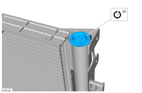
Remove the receiver/drier cap.
 |
-
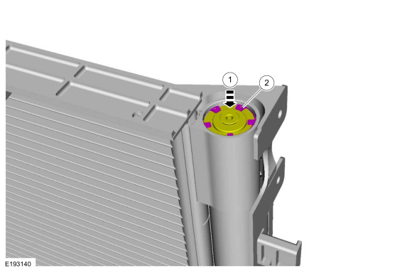
Push the receiver drier plug upwards and remove the receiver drier plug snap ring.
 |
-
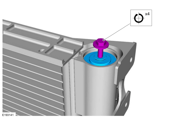
Install an M5 bolt in the center of the receiver drier plug and remove the receiver drier plug.
 |
-
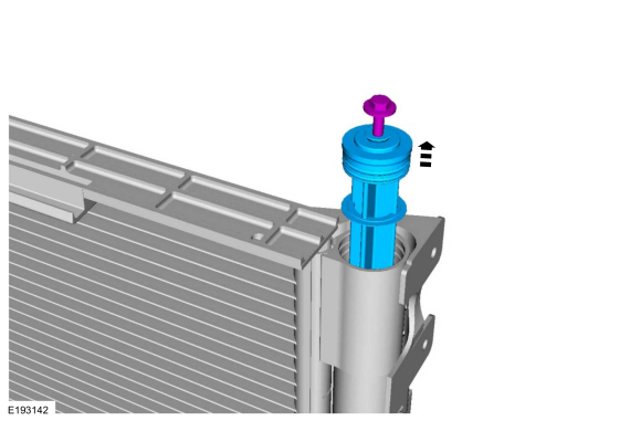
Remove the receiver drier plug and the desiccant bag.
-
Make sure to cover any open ports to prevent debris from entering the system.
-
Make sure to cover any open ports to prevent debris from entering the system.
 |
Installation
-
To install, reverse the removal procedure.
-
NOTICE: Only use the specified material to lubricate the seals.
Install and lubricate new O-ring seals. Refer to the appropriate Specifications in Group 412.
-
Lubricate the refrigerant system with the correct amount
of clean PAG oil. Refer to the appropriate Refrigerant Oil Adding
procedure in Group 412.
 Condenser. Removal and Installation
Removal
NOTICE:
During the removal of components, cap, tape or otherwise
appropriately protect all openings to prevent the ingress of dirt or
other contamination...
 Driver Side Footwell Air Discharge Temperature Sensor. Removal and Installation
Removal
NOTE:
Removal steps in this procedure may contain installation details.
Remove the climate control housing.
Refer to: Climate Control Housing (412-00 Climate Control System - General Information, Removal and Installation)...
Other information:
Lincoln Navigator 2018-2026 Workshop Manual: Engine. Assembly
Special Tool(s) / General Equipment 100-002 (TOOL-4201-C) Holding Fixture with Dial Indicator Gauge 205-142 (T80T-4000-J) Installer, Differential Bearing Cone 205-149 (T80T-4000-R) Installer, Spindle Bearing 205-153 (T80T-4000-W) Handle 303-102Installer, Crankshaft Pulley 303-1246Engine Spreader BarTKIT-2006UF-FLMTK..
Lincoln Navigator 2018-2026 Workshop Manual: Transmission Fluid Drain and Refill. General Procedures
Special Tool(s) / General Equipment Fluid Suction Gun Universal Fluid Dispenser Materials Name Specification Motorcraft® MERCON® ULV Automatic Transmission FluidXT-12-QULV WSS-M2C949-A, MERCON® ULV Draining NOTE: It is not necessary to remove the transmission fluid filter to drain the transmission fluid. Remove the ..
Categories
- Manuals Home
- 4th Gen Lincoln Navigator Service Manual (2018 - 2026)
- Body and Paint
- Transmission Fluid Level Check. General Procedures
- Windshield Washer Pump. Removal and Installation
- Liftgate Trim Panel. Removal and Installation
- Telematics Control Unit (TCU) Module. Removal and Installation
Rear Drive Halfshafts. Diagnosis and Testing
Preliminary Inspection
Visually inspect the CV joints, housing, boots, and clamps for obvious signs of mechanical damage.If an obvious cause for an observed or reported concern is found, correct the cause (if possible) before proceeding to the next step
If the cause is not visually evident, verify the symptom and REFER to Symptom Chart: NVH.
