Lincoln Navigator: Climate Control System - General Information / Cabin Heater Coolant Pump. Removal and Installation
Special Tool(s) / General Equipment
| Hose Clamp Remover/Installer | |
| Fluid Container | |
| Locking Pliers |
Removal
NOTE: Removal steps in this procedure may contain installation details.
-


 WARNING:
Always allow the engine to cool before opening the
cooling system. Do not unscrew the coolant pressure relief cap when the
engine is operating or the cooling system is hot. The cooling system is
under pressure; steam and hot liquid can come out forcefully when the
cap is loosened slightly. Failure to follow these instructions may
result in serious personal injury.
WARNING:
Always allow the engine to cool before opening the
cooling system. Do not unscrew the coolant pressure relief cap when the
engine is operating or the cooling system is hot. The cooling system is
under pressure; steam and hot liquid can come out forcefully when the
cap is loosened slightly. Failure to follow these instructions may
result in serious personal injury.
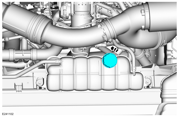
Release the cooling system pressure by slowly turning the pressure relief cap between 2 and 3 turns and remove the pressure relief cap.
WARNING:
When releasing the cooling system pressure, cover the coolant expansion tank cap with a thick cloth.
 |
-
Remove the RH air cleaner outlet pipe.
Refer to: Air Cleaner Outlet Pipe RH (303-12 Intake Air Distribution and Filtering - 3.5L EcoBoost (272kW/370PS), Removal and Installation).
-
Remove the RH
CAC intake pipe.
Refer to: Charge Air Cooler (CAC) Intake Pipe (303-12 Intake Air Distribution and Filtering - 3.5L EcoBoost (272kW/370PS), Removal and Installation).
-
-
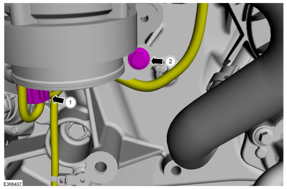
Disconnect electrical connector.
-
Remove the bolt.
Torque: 62 lb.in (7 Nm)
-
Disconnect electrical connector.
 |
-
-
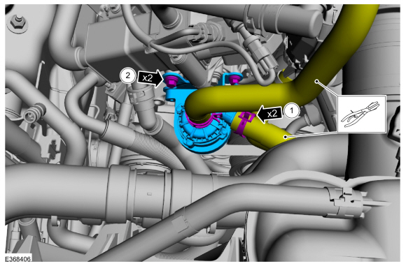
Release hose clamps and disconnect inlet and outlet coolant hoses.
Use the General Equipment: Fluid Container
Use the General Equipment: Locking Pliers
Use the General Equipment: Hose Clamp Remover/Installer
-
Remove the bolts and the cabin heater coolant pump.
Torque: 62 lb.in (7 Nm)
-
Release hose clamps and disconnect inlet and outlet coolant hoses.
 |
Installation
-
To install, reverse the removal procedure.
-
Fill and bleed the cooling system.
Refer to: Engine Cooling System Draining, Vacuum Filling and Bleeding (303-03 Engine Cooling - 3.5L EcoBoost (272kW/370PS), General Procedures).
 Cabin Air Filter. Removal and Installation
Removal
NOTE:
Removal steps in this procedure may contain installation details.
Remove the glove compartment.
Refer to: Glove Compartment (501-12 Instrument Panel and Console, Removal and Installation)...
 Center Registers. Removal and Installation
Special Tool(s) /
General Equipment
Interior Trim Remover
Removal
NOTE:
Removal steps in this procedure may contain installation details...
Other information:
Lincoln Navigator 2018-2026 Workshop Manual: Engine Mount LH. Removal and Installation
Special Tool(s) / General Equipment 303-1246Engine Spreader BarTKIT-2006UF-FLMTKIT-2006UF-ROW 303-1654Lift Eyes 303-F070Support Bar, EngineTKIT-1999A-F/LTTKIT-1999A-FM/FLM Vehicle/Axle Stands Removal NOTICE: Use care when positioning the front axle housing or the vacuum lines to the axle solenoid may become disconnected or damaged...
Lincoln Navigator 2018-2026 Workshop Manual: Second Row Single Seat Armrest. Removal and Installation
Removal NOTE: Removal steps in this procedure may contain installation details. Unzip the second row single seat armrest cover. Remove the second row single seat armrest. Invert the single seat armrest cover to access the armrest pivot bolt...
Categories
- Manuals Home
- 4th Gen Lincoln Navigator Service Manual (2018 - 2026)
- Brake Service Mode Activation and Deactivation. General Procedures
- Body and Paint
- Transmission Fluid Drain and Refill. General Procedures
- Head Up Display (HUD) Module Calibration. General Procedures
- Rear View Mirrors - System Operation and Component Description. Description and Operation
Rear Stabilizer Bar Link. Removal and Installation
Removal
NOTE: Removal steps in this procedure may contain installation details.
With the vehicle in NEUTRAL, position it on a hoist.Refer to: Jacking and Lifting (100-02 Jacking and Lifting, Description and Operation).
NOTE: Use the hex-holding feature to prevent the stud from turning while removing the nut.
Remove and discard the 2 rear stabilizer bar link nuts and remove the rear stabilizer bar link.Torque: 46 lb.ft (63 Nm)