Lincoln Navigator: Engine - 3.5L EcoBoost (272kW/370PS) / Valve Cover RH. Removal and Installation
Special Tool(s) / General Equipment
 |
205-142
(T80T-4000-J)
Installer, Differential Bearing Cone |
 |
205-153
(T80T-4000-W)
Handle |
 |
303-1247 VCT Spark Plug Tube Seal Remover and Installer TKIT-2006UF-FLM TKIT-2006UF-ROW |
Materials
| Name | Specification |
|---|---|
| Motorcraft® High Performance Engine RTV Silicone TA-357 |
WSE-M4G323-A6 |
| Motorcraft® Silicone Gasket Remover ZC-30-A, AZC-30-C |
- |
| Motorcraft® Metal Surface Prep Wipes ZC-31-B |
- |
Removal
NOTICE: During engine repair procedures, cleanliness is extremely important. Any foreign material, including any material created while cleaning gasket surfaces that enters the oil passages, coolant passages or the oil pan, can cause engine failure.
NOTE: Installation of new spark plug seals or VCT solenoid seals is only required if seals are damaged.
-
With the vehicle in NEUTRAL, position it on a hoist.
Refer to: Jacking and Lifting (100-02 Jacking and Lifting, Description and Operation).
-
Remove the intake manifold.
Refer to: Intake Manifold (303-01 Engine - 3.5L EcoBoost (272kW/370PS), Removal and Installation).
-
Remove the RH ignition coil-on-plugs.
Refer to: Ignition Coil-On-Plug (303-07 Engine Ignition - 3.5L EcoBoost (272kW/370PS), Removal and Installation).
-
Disconnect the RH
TC electrical connector.
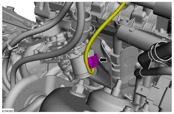 |
-
Disconnect the PCM electrical connectors and the pin-type retainer.
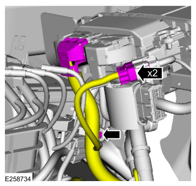 |
-
-
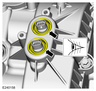
Disconnect the VCT solenoid electrical connectors and the wire retainers.
-
Detach the wiring harness retainers.
-
Disconnect the VCT solenoid electrical connectors and the wire retainers.
 |
-
NOTICE: While removing the valve cover do not apply excessive force to the VCT oil control solenoid or damage may occur.
NOTICE: If the VCT oil control solenoid sticks to the VCT seal, carefully wiggle the valve cover until the bond breaks free or damage to the VCT seal and VCT oil control solenoid may occur.
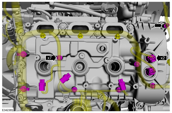
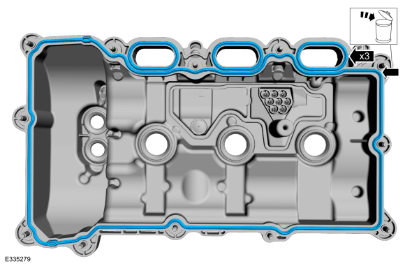
Remove the studbolts, bolts and the valve cover.
 |
-
Remove and discard the valve cover and intake port gaskets.
 |
-
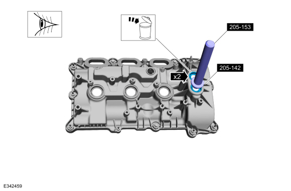
NOTE: Inspect the VCT solenoid seals. Remove any damaged seals.
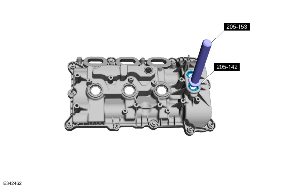
If necessary, using the special tools, remove the VCT solenoid seals.
Use Special Service Tool: 205-142 (T80T-4000-J) Installer, Differential Bearing Cone. , 205-153 (T80T-4000-W) Handle.
 |
-
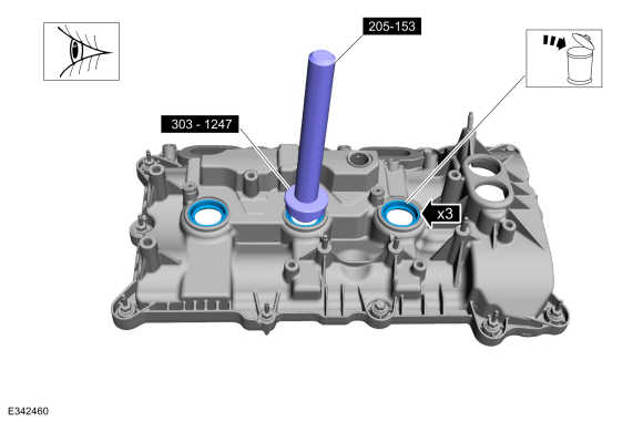
NOTE: Inspect the spark plug tube seals. Remove any damaged seals.
If necessary, using the special tools, remove the spark plug tube seals.
Use Special Service Tool: 303-1247 VCT Spark Plug Tube Seal Remover and Installer. , 205-153 (T80T-4000-W) Handle.
 |
-
Clean the valve cover, cylinder head and engine front cover sealing surfaces with metal surface prep.
Material: Motorcraft® Metal Surface Prep Wipes / ZC-31-B
Installation
-
NOTE: Installation of new seals is only required if damaged seals were removed.
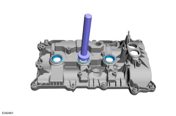
If removed, using the special tools, install the spark plug tube seals.
Use Special Service Tool: 303-1247 VCT Spark Plug Tube Seal Remover and Installer. , 205-153 (T80T-4000-W) Handle.
 |
-
NOTE: Installation of new seals is only required if damaged seals were removed.
If removed, using the special tools, install the VCT oil control solenoid seals.
Use Special Service Tool: 205-142 (T80T-4000-J) Installer, Differential Bearing Cone. , 205-153 (T80T-4000-W) Handle.
 |
-
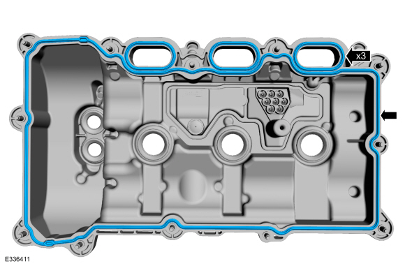
Install the new valve cover and intake port gaskets.
 |
-
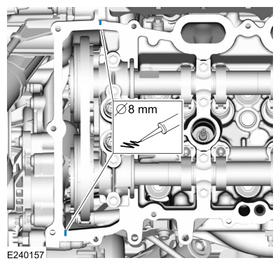
NOTE: If the valve cover is not installed and the fasteners tightened within 4 minutes, the sealant must be removed and the sealing area cleaned. To clean the sealing area, use silicone gasket remover and metal surface prep. Failure to follow this procedure can cause future oil leakage.
Apply an 8 mm (0.31 in) bead of Motorcraft® High Performance Engine RTV Silicone to the engine front cover-to-cylinder head joints.
Material: Motorcraft® Metal Surface Prep Wipes / ZC-31-B
Material: Motorcraft® Silicone Gasket Remover / ZC-30-A, AZC-30-C
Material: Motorcraft® High Performance Engine RTV Silicone / TA-357 (WSE-M4G323-A6)
 |
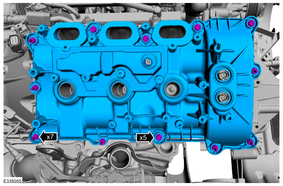
-
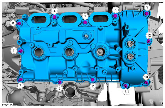
Install the valve cover and tighten the studbolts, bolts in the sequence shown.
Torque: 89 lb.in (10 Nm)
 |
-
Make sure the VCT seals in the valve cover are below the top of the VCT
oil control solenoid electrical connector or the VCT seal may leak oil.
 |
-
-
Connect the VCT solenoid electrical connectors.
-
Attach the wiring harness retainers.
-
Connect the VCT solenoid electrical connectors.
|
-
Connect the RH
TC electrical connector.
|
-
Connect the PCM electrical connectors and the pin-type retainer.
|
-
Install the RH ignition coil-on-plugs.
Refer to: Ignition Coil-On-Plug (303-07 Engine Ignition - 3.5L EcoBoost (272kW/370PS), Removal and Installation).
-
Install the intake manifold.
Refer to: Intake Manifold (303-01 Engine - 3.5L EcoBoost (272kW/370PS), Removal and Installation).

 Variable Camshaft Timing (VCT) Unit. Removal and Installation
Removal
NOTICE:
During engine repair procedures, cleanliness is extremely
important. Any foreign material, including any material created while
cleaning gasket surfaces, that enters the oil passages, coolant passages
or the oil pan, can cause engine failure...
Other information:
Lincoln Navigator 2018-2026 Workshop Manual: Connecting Rod Bearing Journal Clearance. General Procedures
Check NOTE: Refer to the appropriate Section 303-01 for the specification. NOTE: The crankshaft connecting rod journals must be within specifications to check the connecting rod bearing journal clearance. Remove the connecting rod bearing cap and connecting rod bearing...
Lincoln Navigator 2018-2026 Workshop Manual: Washer Hose Coupling. General Procedures
Disconnect WARNING: Before beginning any service procedure in this section, refer to Safety Warnings in section 100-00 General Information. Failure to follow this instruction may result in serious personal injury. Refer to: Health and Safety Precautions (100-00 General Information, Description and Operation)...
Categories
- Manuals Home
- 4th Gen Lincoln Navigator Service Manual (2018 - 2026)
- Front Bumper Cover. Removal and Installation
- Identification Codes. Description and Operation
- Remote Function Actuator (RFA) Module. Removal and Installation
- Body and Paint
- Vehicle Dynamics Control Module (VDM). Removal and Installation
Front Driveshaft. Removal and Installation
Special Tool(s) / General Equipment
Crimping ToolMaterials
Name Specification Motorcraft® Premium Long-Life GreaseXG-1-E1 ESA-M1C75-B
Removal
With the vehicle in NEUTRAL, position the vehicle on a hoist.Refer to: Jacking and Lifting (100-02 Jacking and Lifting, Description and Operation).
Remove the bolts and the transmission shield.