Lincoln Navigator: Engine - 3.5L EcoBoost (272kW/370PS) / Valve Cover LH. Removal and Installation
Special Tool(s) / General Equipment
 |
205-142
(T80T-4000-J)
Installer, Differential Bearing Cone |
 |
205-153
(T80T-4000-W)
Handle |
 |
303-1247 VCT Spark Plug Tube Seal Remover and Installer TKIT-2006UF-FLM TKIT-2006UF-ROW |
Materials
| Name | Specification |
|---|---|
| Motorcraft® High Performance Engine RTV Silicone TA-357 |
WSE-M4G323-A6 |
| Motorcraft® Silicone Gasket Remover ZC-30-A, AZC-30-C |
- |
| Motorcraft® Metal Surface Prep Wipes ZC-31-B |
- |
Removal
NOTICE: During engine repair procedures, cleanliness is extremely important. Any foreign material, including any material created while cleaning gasket surfaces that enters the oil passages, coolant passages or the oil pan, can cause engine failure.
NOTE: Installation of new spark plug seals or VCT seals is only required if seals are damaged.
-
Remove the intake manifold.
Refer to: Intake Manifold (303-01 Engine - 3.5L EcoBoost (272kW/370PS), Removal and Installation).
-
Remove the air cleaner assembly.
Refer to: Air Cleaner (303-12 Intake Air Distribution and Filtering - 3.5L EcoBoost (272kW/370PS), Removal and Installation).
-
Remove the high pressure fuel pump.
Refer to: High-Pressure Fuel Pump (303-04A Fuel Charging and Controls - 3.5L EcoBoost (272kW/370PS), Removal and Installation).
-
-
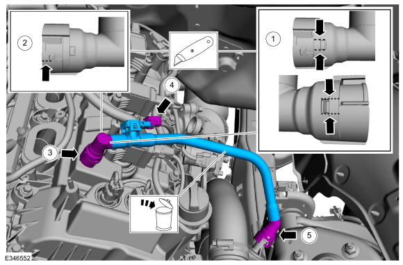
Cut the housing above the lock tabs.
-
Cut the housing arm retainer.
-
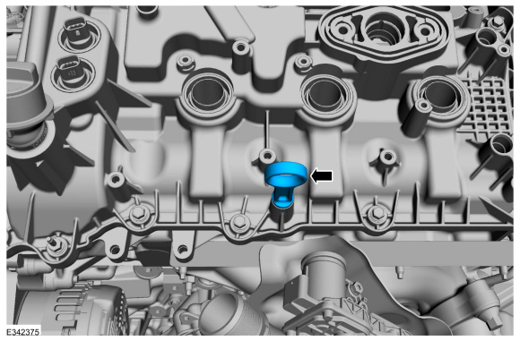
Remove the housing and retainer from the valve cover spigot.
-
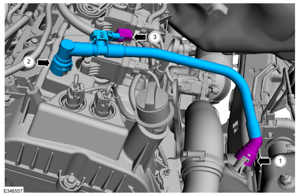
Disconnect the PCV pressure sensor electrical connector.
-
Follow directions to disconnect the quick release coupling type 4.
Disconnect the PCV tube quick connect coupling, remove and discard the
tube.
Refer to: Quick Release Coupling (310-00 Fuel System - General Information - 3.5L EcoBoost (272kW/370PS), General Procedures).
-
Cut the housing above the lock tabs.
 |
-
Remove the LH
CAC intake pipe.
Refer to: Charge Air Cooler (CAC) Intake Pipe (303-12 Intake Air Distribution and Filtering - 3.5L EcoBoost (272kW/370PS), Removal and Installation).
-
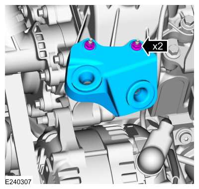
Remove the nuts and the CAC tube bracket.
 |
-
Remove the LH ignition coil-on-plugs.
Refer to: Ignition Coil-On-Plug (303-07 Engine Ignition - 3.5L EcoBoost (272kW/370PS), Removal and Installation).
-
-
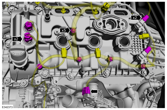
Disconnect the VCT sensor electrical connectors.
-
Detach the wiring harness retainers and position the harness aside.
-
Disconnect the CMP sensor electrical connectors.
-
Disconnect the LH
TC electrical connector.
-
Disconnect the VCT sensor electrical connectors.
 |
-
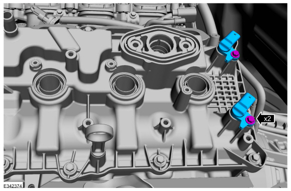
Remove the bolts and the CMP sensors.
 |
-
Remove the oil level indicator.
 |
-
NOTICE: While removing the valve cover do not apply excessive force to the VCT oil control solenoid or damage may occur.
NOTICE: If the VCT oil control solenoid sticks to the VCT seal, carefully wiggle the valve cover until the bond breaks free or damage to the VCT seal and VCT oil control solenoid may occur.
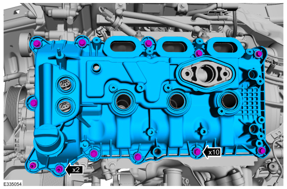
Remove the fasteners and the valve cover.
 |
-
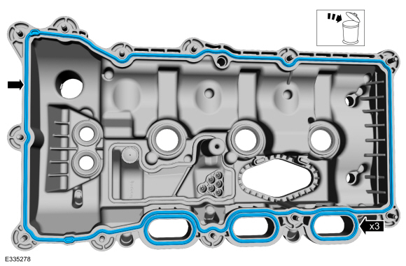
Remove and discard the valve cover and intake port gaskets.
 |
-
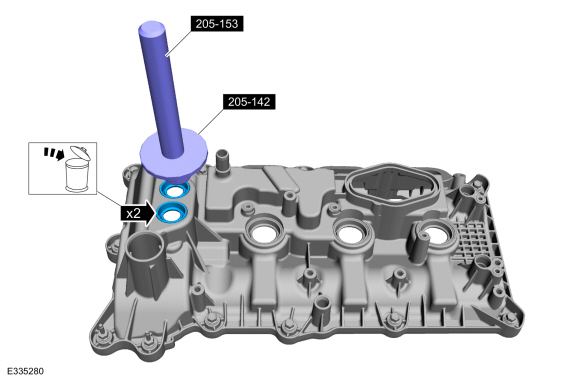
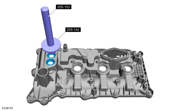
NOTE: Inspect the VCT oil control solenoid seals. Remove any damaged seals.
If necessary, using the special tools, remove the VCT oil control solenoid seals.
Use Special Service Tool: 205-142 (T80T-4000-J) Installer, Differential Bearing Cone. , 205-153 (T80T-4000-W) Handle.
 |
-
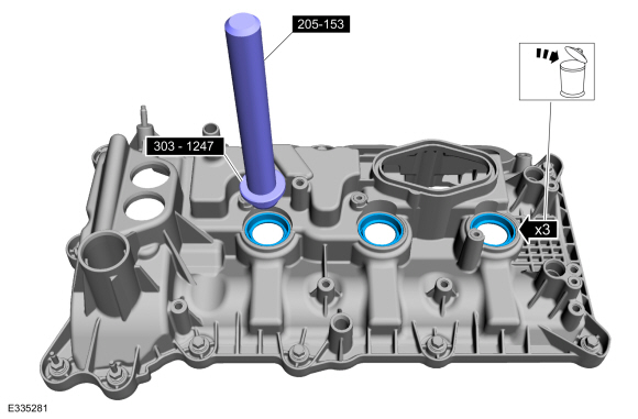
NOTE: Inspect the spark plug tube seals. Remove any damaged seals.
If necessary, using the special tools, remove the spark plug tube seals.
Use Special Service Tool: 303-1247 VCT Spark Plug Tube Seal Remover and Installer. , 205-153 (T80T-4000-W) Handle.
 |
-
Clean the valve cover, cylinder head and engine front cover sealing surfaces with metal surface prep.
Material: Motorcraft® Metal Surface Prep Wipes / ZC-31-B
Installation
-
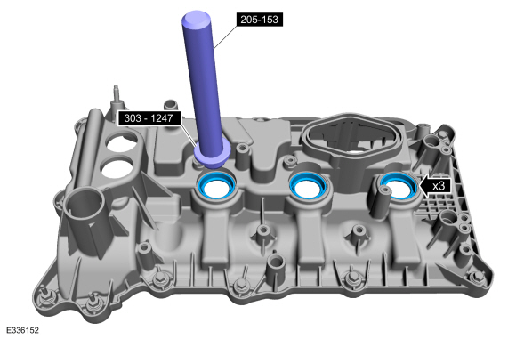
NOTE: Installation of new seals is only required if damaged seals were removed.
If removed, using the special tools, install the spark plug tube seals.
Use Special Service Tool: 303-1247 VCT Spark Plug Tube Seal Remover and Installer. , 205-153 (T80T-4000-W) Handle.
 |
-
NOTE: Installation of new seals is only required if damaged seals were removed.
If removed, using the special tools, install the VCT oil control solenoid seals.
Use Special Service Tool: 205-142 (T80T-4000-J) Installer, Differential Bearing Cone. , 205-153 (T80T-4000-W) Handle.
 |
-
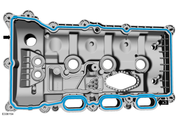
Install the new valve cover and intake port gaskets.
 |
-
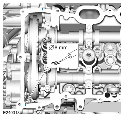
NOTE: If the valve cover is not installed and the fasteners tightened within 4 minutes, the sealant must be removed and the sealing area cleaned. To clean the sealing area, use silicone gasket remover and metal surface prep. Failure to follow this procedure can cause future oil leakage.
Apply an 8 mm (0.31 in) bead of Motorcraft® High Performance Engine RTV Silicone to the engine front cover-to-cylinder head joints.
Material: Motorcraft® Metal Surface Prep Wipes / ZC-31-B
Material: Motorcraft® Silicone Gasket Remover / ZC-30-A, AZC-30-C
Material: Motorcraft® High Performance Engine RTV Silicone / TA-357 (WSE-M4G323-A6)
 |
-
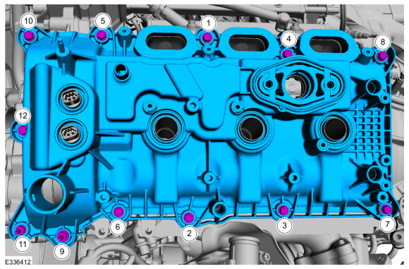
Install the valve cover and tighten the fasteners in the sequence shown.
Torque: 89 lb.in (10 Nm)
 |
-
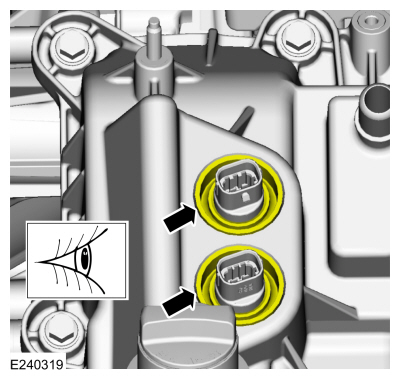
Make sure the VCT seals in the valve cover are below the top of the VCT
oil control solenoid electrical connector or the VCT seal may leak oil.
 |
-
Install the oil level indicator.
|
-
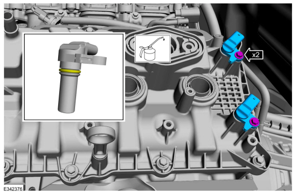
NOTE: Before installation, lubricate the CMP sensor O-ring seal with clean engine oil.
Install the CMP sensors and the bolts.
Refer to: Specifications (303-01 Engine - 3.5L EcoBoost (BM)) .
Torque: 71 lb.in (8 Nm)
 |
-
-
Position the wiring harness and attach the wiring harness retainers.
-
Connect the VCT sensor electrical connectors.
-
Connect the CMP sensor electrical connectors.
-
Connect the LH
TC electrical connector.
-
Position the wiring harness and attach the wiring harness retainers.
|
-
Install the LH ignition coil-on-plugs.
Refer to: Ignition Coil-On-Plug (303-07 Engine Ignition - 3.5L EcoBoost (272kW/370PS), Removal and Installation).
-
Install the CAC tube bracket and nuts.
Torque: 53 lb.in (6 Nm)
|
-
Install the LH
CAC intake pipe.
Refer to: Charge Air Cooler (CAC) Intake Pipe (303-12 Intake Air Distribution and Filtering - 3.5L EcoBoost (272kW/370PS), Removal and Installation).
-
-
Follow directions to connect the quick release
coupling type 4 to the turbo charger outlet tube. Install the new PCV tube.
Refer to: Quick Release Coupling (310-00 Fuel System - General Information - 3.5L EcoBoost (272kW/370PS), General Procedures).
-
Connect the new PCV housing to the valve cover spigot.
-
Connect the PCV pressure sensor electrical connector.
-
Follow directions to connect the quick release
coupling type 4 to the turbo charger outlet tube. Install the new PCV tube.
 |
-
Install the air cleaner assembly.
Refer to: Air Cleaner (303-12 Intake Air Distribution and Filtering - 3.5L EcoBoost (272kW/370PS), Removal and Installation).
-
Install the intake manifold.
Refer to: Intake Manifold (303-01 Engine - 3.5L EcoBoost (272kW/370PS), Removal and Installation).
 Timing Chain Tensioner. Removal and Installation
Special Tool(s) /
General Equipment
303-1655Tool, Camshaft Holding
Removal
NOTICE:
During engine repair procedures, cleanliness is extremely
important...
 Valve Cover RH. Removal and Installation
Special Tool(s) /
General Equipment
205-142
(T80T-4000-J)
Installer, Differential Bearing Cone
205-153
(T80T-4000-W)
Handle
303-1247VCT Spark Plug Tube Seal Remover and InstallerTKIT-2006UF-FLMTKIT-2006UF-ROW
Materials
Name
Specification
Motorcraft® High Performance Engine RTV SiliconeTA-357
WSE-M4G323-A6
Motorcra..
Other information:
Lincoln Navigator 2018-2026 Workshop Manual: Lane Keeping System - Component Location. Description and Operation
Component Location - Lane Keeping System Item Description 1 IPMA camera 2 IPMA 3 Lane keeping system switch ..
Lincoln Navigator 2018-2026 Workshop Manual: Passive Anti-Theft System (PATS) - System Operation and Component Description. Description and Operation
System Operation System Diagram Item Description 1 IPC 2 Passive Key 3 RTM 4 GWM 5 GWM 6 PCM 7 PATS Center Antenna 8 Keyless Entry Rear Antenna 9 Ignition Switch 10 PATS Enable 11 BCM Netwo..
Categories
- Manuals Home
- 4th Gen Lincoln Navigator Service Manual (2018 - 2026)
- Transmission Fluid Drain and Refill. General Procedures
- Transmission Fluid Level Check. General Procedures
- Rear Bumper. Removal and Installation
- Brake Service Mode Activation and Deactivation. General Procedures
- Front Bumper Cover. Removal and Installation
Axle Tube Bearing. Removal and Installation
Special Tool(s) / General Equipment
 205-123
(T78P-1177-A)
205-123
(T78P-1177-A)
Installer, Axle Shaft Oil Seal
 308-047
(T77F-1102-A)
308-047
(T77F-1102-A)
Remover, Bearing Cup Slide Hammer