Lincoln Navigator: Engine - 3.5L EcoBoost (272kW/370PS) / Timing Chain Tensioner. Removal and Installation
Special Tool(s) /
General Equipment
 |
303-1655
Tool, Camshaft Holding |
Removal
NOTICE:
During engine repair procedures, cleanliness is extremely
important. Any foreign material, including any material created while
cleaning gasket surfaces, that enters the oil passages, coolant passages
or the oil pan may cause engine failure.
RH and LH tensioners
-
Remove the engine front cover.
Refer to: Engine Front Cover (303-01 Engine - 3.5L EcoBoost (272kW/370PS), Removal and Installation).
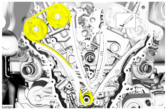
RH timing chain tensioner
-
-
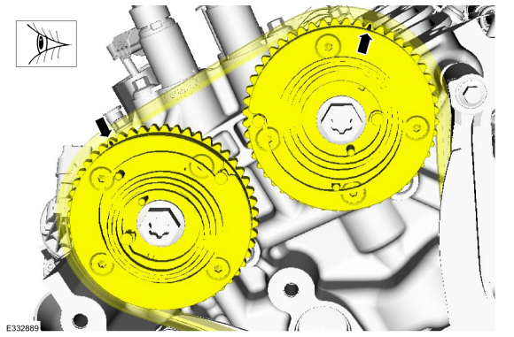
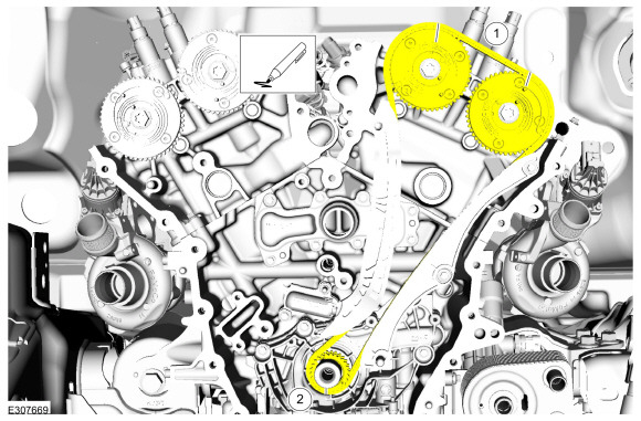
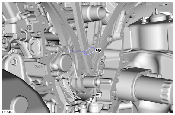
Scribe a location mark on the RH timing chain and the VCT units.
-
Scribe a location mark on the RH timing chain and the crankshaft sprocket.
-
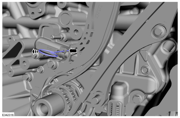
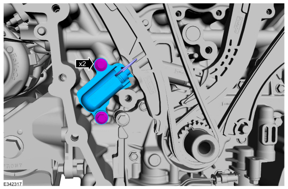
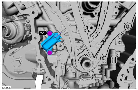
Remove the bolts and the RH timing chain tensioner.
LH timing chain tensioner
-
Install the crankshaft pulley bolt.
-
-
Rotate the crankshaft clockwise.
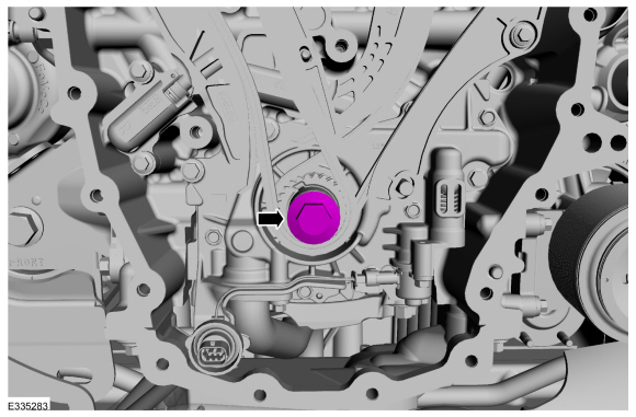
-
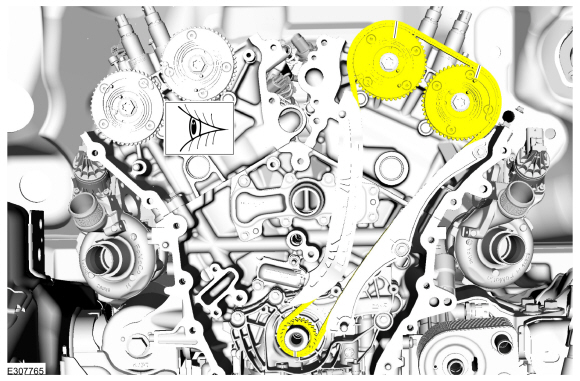
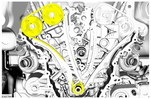
Position the crankshaft sprocket keyway at the 11 o'clock position.
-
Verify the timing marks on the VCT units are at the positions shown.
-
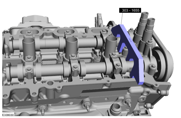
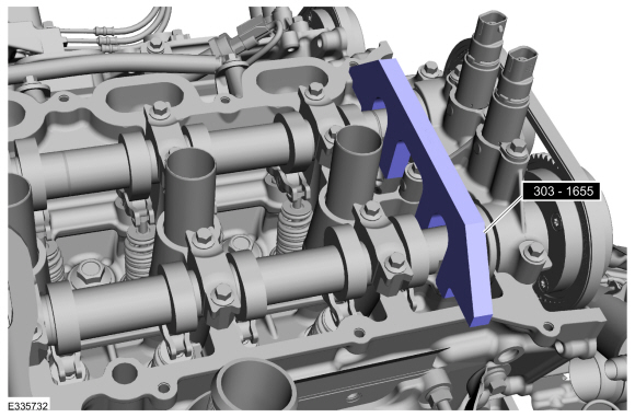
NOTE:
The Camshaft Holding Tool will hold the camshafts in the TDC position.
Install Special Service Tool: 303-1655
Tool, Camshaft Holding.
-
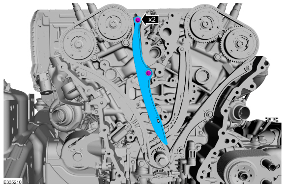
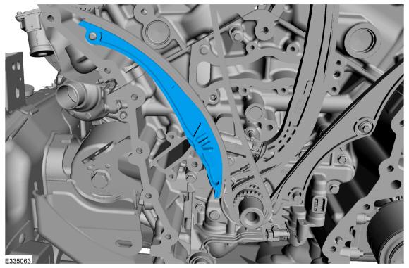
Remove the bolts and the RH timing chain guide.
-
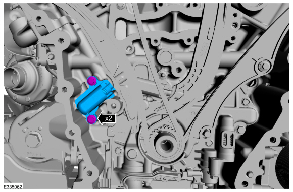
Remove the bolts and the RH timing chain tensioner.
-
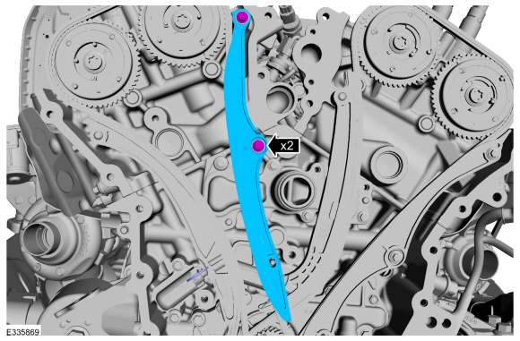
Remove the RH timing chain tensioner arm.
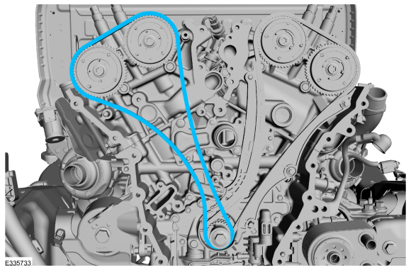
-
Remove the RH timing chain.
-
-
Scribe a location mark on the LH timing chain and the VCT units.
-
Scribe a location mark on the LH timing chain and the crankshaft sprocket.
-
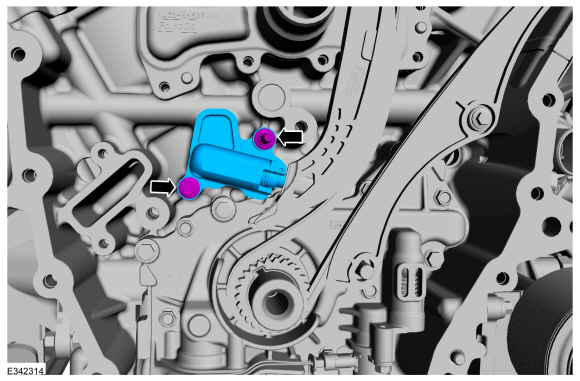
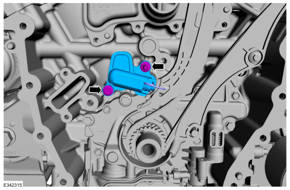
Remove the bolts and the LH timing chain tensioner.
Installation
LH timing chain tensioner
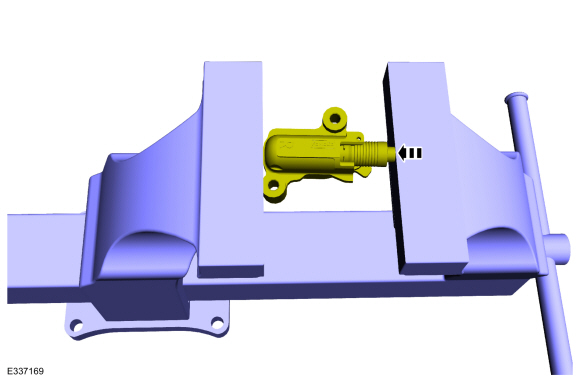
-
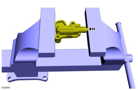
Position the tensioner in a soft-jawed vise.
-
NOTE:
Use of a commercially available tools with a
curved radius in the range of 10mm - 15mm is suggested for use in
resetting the ratchet clip. Examples are a 8mm closed end wrench,
12x12mm piece of bar stock, T40 to T50 Torx screwdriver or 3/8 wobble
style socket extender.
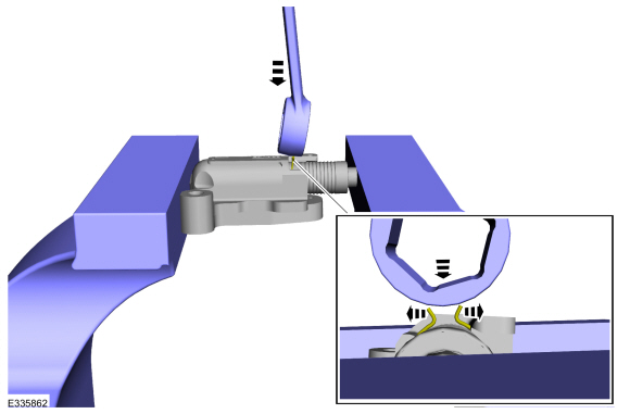
Using a commercially available wrench, push down on the ratchet clip so the ratchet clip pushes outward.
-
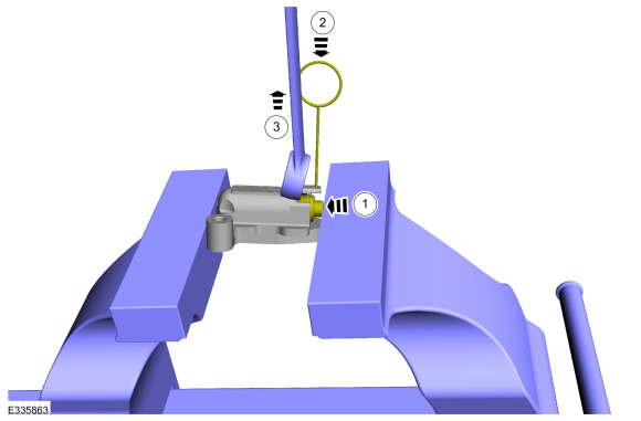
-
Using the soft-jawed vise, compress the piston to the reset position.
-
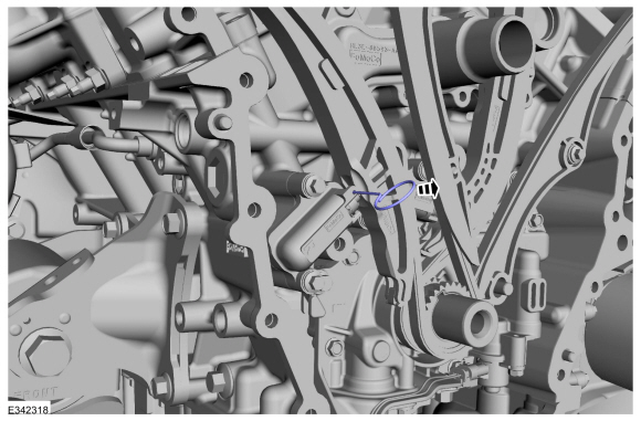
Install a locking pin in the 2 holes of the tensioner body to hold the piston in place.
-
Remove the commercially available tool and the tensioner.
-
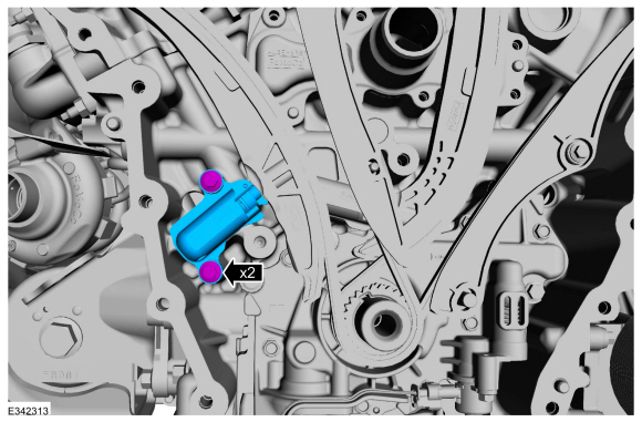
Position the LH timing chain tensioner with the end of the tensioner
correctly engaged to the tensioner arm and install the fasteners.
Torque:
Stage 1:
89 lb.in (10 Nm)
Stage 2:
30°
-
Remove the tensioner pin.
-
Verify all scribe marks align.
-
NOTE:
The crankshaft sprocket is reversible with a
timing mark on each face. For installation of each timing chain, utilize
the timing mark on the front face of the crankshaft sprocket for chain
alignment.
-
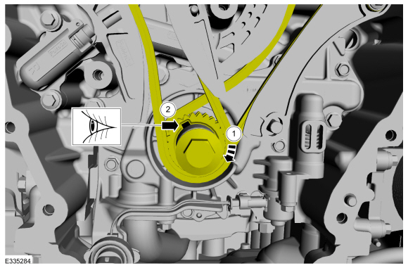
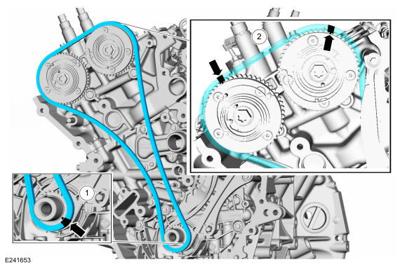
Install the RH timing chain with the single colored links aligned with the timing marks on the VCT units.
-
Install the double colored links so they straddle the timing mark on the crankshaft sprocket.
-
Install the RH timing chain tensioner arm.
-
Position the tensioner in a soft-jawed vise.
-
NOTE:
Use of a commercially available tools with a
curved radius in the range of 10mm - 15mm is suggested for use in
resetting the ratchet clip. Examples are a 8mm closed end wrench,
12x12mm piece of bar stock, T40 to T50 Torx screwdriver or 3/8 wobble
style socket extender.
Using a commercially available wrench, push down on the ratchet clip so the ratchet clip pushes outward.
-
-
Using the soft-jawed vise, compress the piston to the reset position.
-
Install a locking pin in the 2 holes of the tensioner body to hold the piston in place.
-
Remove the commercially available tool and the tensioner.
-
Position the RH timing chain tensioner with the end of the tensioner
correctly engaged to the tensioner arm and install the fasteners.
Torque:
Stage 1:
89 lb.in (10 Nm)
Stage 2:
30°
-
Install the RH timing chain guide and bolts.
Torque:
Stage 1:
89 lb.in (10 Nm)
Stage 2:
30°
-
Remove the tensioner pins.
-
Remove the crankshaft pulley bolt.
-
Remove Special Service Tool: 303-1655
Tool, Camshaft Holding.
RH timing chain tensioner
-
Position the tensioner in a soft-jawed vise.
-
NOTE:
Use of a commercially available tools with a
curved radius in the range of 10mm - 15mm is suggested for use in
resetting the ratchet clip. Examples are a 8mm closed end wrench,
12x12mm piece of bar stock, T40 to T50 Torx screwdriver or 3/8 wobble
style socket extender.
Using a commercially available wrench, push down on the ratchet clip so the ratchet clip pushes outward.
-
-
Using the soft-jawed vise, compress the piston to the reset position.
-
Install a locking pin in the 2 holes of the tensioner body to hold the piston in place.
-
Remove the commercially available tool and the tensioner.
-
Position the RH timing chain tensioner with the end of the tensioner
correctly engaged to the tensioner arm and install the fasteners.
Torque:
89 lb.in (10 Nm)
-
Remove the tensioner pin.
-
Verify all scribe marks align.
RH and LH tensioners
-
Install the engine front cover.
Refer to: Engine Front Cover (303-01 Engine - 3.5L EcoBoost (272kW/370PS), Removal and Installation).
Special Tool(s) /
General Equipment
303-1655Tool, Camshaft Holding
Removal
NOTICE:
During engine repair procedures, cleanliness is extremely
important...
Special Tool(s) /
General Equipment
205-142
(T80T-4000-J)
Installer, Differential Bearing Cone
205-153
(T80T-4000-W)
Handle
303-1247VCT Spark Plug Tube Seal Remover and InstallerTKIT-2006UF-FLMTKIT-2006UF-ROW
Materials
Name
Specification
Motorcraft® High Performance Engine RTV SiliconeTA-357
WSE-M4G323-A6
Motorcra..
Other information:
Special Tool(s) /
General Equipment
Grinder
Plasma Cutter
MIG/MAG Welding Equipment
Locking Pliers
Removal
NOTE:
The following procedure provides steps to replace the front
frame short section at the first frame crossmember or the frame section
at the center rail joint depending on the extent of vehicle damage.
Restore the vehicl..
Special Tool(s) /
General Equipment
6.5 mm Drill Bit
Polydrive Bit Socket
Self-Piercing Rivet (SPR) Remover/Installer
Belt Sander
Blind Rivet Gun
Hot Air Gun
Locking Pliers
Materials
Name
Specification
Metal Bonding AdhesiveTA-1, TA-1-B, 3M™ 08115, LORD Fusor® 108B, Henkel Teroson EP 5055
-
Flexib..
 Timing Chain Tensioner. Removal and Installation
 Valve Cover LH. Removal and Installation
 205-1016
 205-153
(T80T-4000-W)
205-153
(T80T-4000-W)
 205-D061
(D83T-4205-C2)
205-D061
(D83T-4205-C2)