Lincoln Navigator: Automatic Transmission - 10-Speed Automatic Transmission – 10R80 / Transmission Fluid Pump Idler Gear. Removal and Installation
Special Tool(s) /
General Equipment
 |
205-1018
Installation Tube |
 |
307-003
(T57L-500-B)
Holding Fixture, Transmission |
 |
307-091
Handle, Torque Converter
TKIT-2009TC-F |
 |
307-346
(T97T-7902-A)
Retainer, Torque Converter
TKIT-1998-LM (NavigatoR)
TKIT-1997-F/FLM/LT |
 |
307-736
Installer, Pump Drive Gear Bearing |
 |
307-737
Press Tool, Oil Pump Drive Idler Gear |
 |
307-743
Remover, Pump Drive Gear |
 |
307-750
Installer, Converter Seal |
| Hydraulic Press |
Removal
-
To remove the transmission assembly.
Refer to: Transmission (307-01 Automatic Transmission - 10-Speed Automatic Transmission – 10R80, Removal).
-
Using the special tool, install the transmission on a bench.
Use Special Service Tool: 307-003
(T57L-500-B)
Holding Fixture, Transmission.
-
Remove the special tool.
Use Special Service Tool: 307-346
(T97T-7902-A)
Retainer, Torque Converter.
-
Using the special tool, remove the torque converter.
Use Special Service Tool: 307-091
Handle, Torque Converter.
-
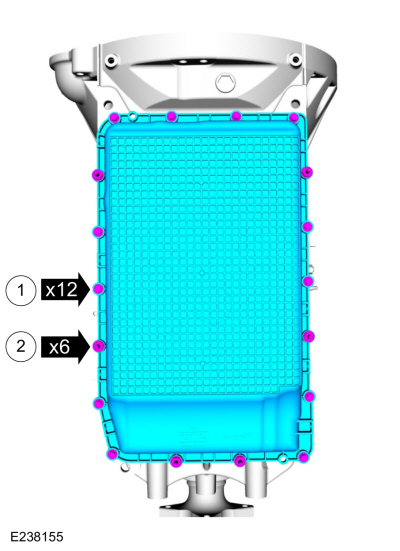
NOTE:
Note the location of the bolts and studbolts for assembly.
Remove the bolts and studbolts and the transmission fluid pan.
-
Bolts
-
Studbolts
-
NOTE:
The transmission fluid pan gasket can be reused if not damaged.
NOTE:
Note the location of the alignment tabs.
Remove the transmission fluid pan gasket.
-
Remove the transmission fluid level indicator and plug assembly.
-
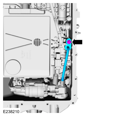
Remove the bolt and the transmission fluid auxiliary pump tube.
-
Remove and discard the transmission fluid auxiliary pump tube seal.
-
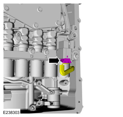
Disconnect the transmission fluid auxiliary pump electrical connector.
-
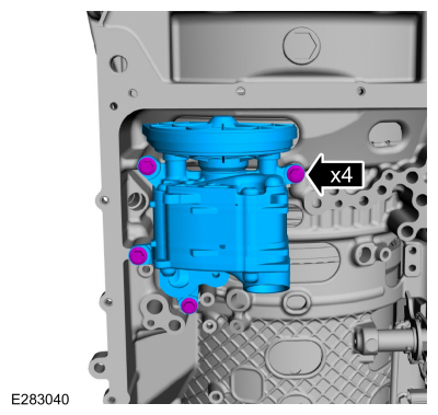
Remove the bolts and the transmission fluid auxiliary pump.
-
-
Remove the 71 mm and 20 mm bolts.
-
Remove and discard the transmission fluid filter (7A098).
-
NOTE:
The transmission fluid filter seal will either come
off with the transmission fluid filter or it will be stuck in the pump.
Remove and discard the transmission fluid filter seal (7Z302).
-
Disconnect the main control main electrical connector.
-
NOTE:
Check to see if the main control-to-transmission fluid pump seal is attached to the main control.
Remove the 68 mm bolts and the main control assembly.
-
Remove the bolts and the transmission fluid pump.
-
-
Remove the transmission fluid pump driven gear outer cover.
-
Remove and discard the retaining ring (W718158) and the transmission fluid pump driven gear (7J048).
-
-
Remove the torque converter hub seal snap ring.
-
NOTE:
When removing the torque converter hub seal use
care not to scratch the front support cover sealing surface.
Remove and discard the torque converter hub seal (7A248).
-
Remove the front support cover bolt and the front support cover snap ring.
-
-
NOTICE:
Do not pry on the transmission fluid pump drive
gear to remove the front support cover or damage to the transmission
fluid pump drive gear can occur.
-
Push up on the back of the front support cover and remove the front support cover from the front support.
-
Remove and discard the transmission fluid pump drive gear (7177).
-
NOTE:
Tighten the special tools uniformly to prevent
damage to the front support bearing post during the fluid pump gear and
bearing removal.
Using the special tools, remove and discard the transmission fluid pump idler gear (6652) and bearing (7025).
Use Special Service Tool: 307-743
Remover, Pump Drive Gear.
-
Remove and discard the stator support seal (7G090).
-
Clean all debris from the front support.
Installation
-
Install the new stator support seal on the front
support. Lubricate the stator support seal with petroleum jelly.
-
Using the special tool and a press, install the new transmission fluid pump idler gear bearing.
Use Special Service Tool: 307-736
Installer, Pump Drive Gear Bearing.
Use the General Equipment: Hydraulic Press
-
-
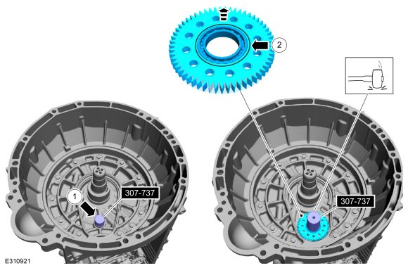
Position the special tool on the front support.
Use Special Service Tool: 307-737
Press Tool, Oil Pump Drive Idler Gear.
-
NOTE:
Install the transmission fluid pump idler gear with the grooved side up.
-
NOTE:
Verify the front pump idler gear and bearing
cannot be pushed onto the front support by hand. If the gear and bearing
can be pushed onto the front support by hand, replace the front
support.
Using the special tools and a dead blow hammer,
install the new transmission fluid pump idler gear and bearing.
-
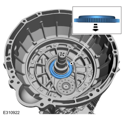
Install the new transmission fluid pump drive gear with the flat side down.
-
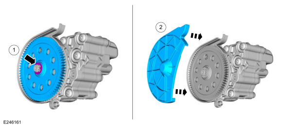
Install the front support cover by pressing down evenly by hand.
-
NOTE:
The front support cover snap ring ends are located in the cover alignment features.
Install the front support cover bolt and the front support cover snap ring.
Torque:
62 lb.in (7 Nm)
-
Install the new torque converter hub seal on the special tools.
Use Special Service Tool: 307-750
Installer, Converter Seal.
, 205-1018
Installation Tube.
-
Using the special tools, install the new torque converter hub seal.
Use Special Service Tool: 307-750
Installer, Converter Seal.
, 205-1018
Installation Tube.
-
Install the torque converter hub seal snap ring.
-
Using the special tool, install the torque converter.
Use Special Service Tool: 307-091
Handle, Torque Converter.
-
Install the special tool to hold the torque converter.
Use Special Service Tool: 307-346
(T97T-7902-A)
Retainer, Torque Converter.
-
-
Install the new transmission fluid pump driven gear and the retaining ring.
-
Install the transmission fluid pump driven gear outer cover.
-
Install the transmission fluid pump and the bolts.
Torque:
71 lb.in (8 Nm)
-
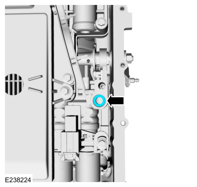
NOTICE:
Do not install a 71 mm length bolt in the location
shown or the transmission clutch and planetary container will be damaged
and result in transmission failure.
Loosely install the main control valve body.
-
NOTE:
Be sure the main control-to-case seal is attached to the main control.
Connect the internal wiring harness electrical connector while installing the main control valve body.
-
If equipped with a park pawl lock valve, align the TR sensor with the park pawl lock valve.
-
Align the guide pins on the main control valve body with the alignment holes in the transmission case.
-
Loosely install the 68 mm length main control-to-transmission case bolts.
-
Tighten the bolts in the sequence shown.
Torque:
89 lb.in (10 Nm)
-
Lock the main control main electrical connector.
-
Install the new filter seal in the pump.
-
NOTICE:
If the bolts are installed in the wrong locations, transmission damage will occur.
Install the new filter and the bolts in the correct locations.
-
Short bolt 20 mm
-
Long bolt 71 mm
-
Torque:
93 lb.in (10.5 Nm)
-
Install the transmission fluid auxiliary pump and loosely install the bolts.
-
Install the new transmission fluid auxiliary pump tube seal.
-
Inspect the transmission fluid auxiliary pump tube O-ring.
-
Install the transmission fluid auxiliary pump tube and loosely install the bolt.
-
-
Transmission fluid auxiliary pump bolts
Torque:
97 lb.in (11 Nm)
-
Transmission fluid auxiliary pump tube bolt
Torque:
106 lb.in (12 Nm)
-
Connect the transmission fluid auxiliary pump electrical connector.
-
Clean and inspect the magnet and the retainer.
-
NOTE:
The transmission fluid pan gasket can be reused if not damaged.
Align the tabs in the noted location and install the transmission fluid pan gasket.
-
NOTE:
Install the bolts and studbolts in the correct locations noted during removal.
Install the transmission fluid pan and loosely install the bolts and studbolts.
-
Tighten the studbolts in a crisscross pattern.
Torque:
106 lb.in (12 Nm)
-
Tighten the bolts in a crisscross pattern.
Torque:
89 lb.in (10 Nm)
-
Install the transmission fluid level indicator.
Torque:
52 lb.ft (70 Nm)
-
To install the transmission assembly.
Refer to: Transmission (307-01 Automatic Transmission - 10-Speed Automatic Transmission – 10R80, Installation).
Removal
Remove the main control valve body.
Refer to: Main Control Valve Body (307-01 Automatic Transmission -
10-Speed Automatic Transmission – 10R80, Removal and Installation)...
Removal
Remove the main control valve body.
Refer to: Main Control Valve Body (307-01 Automatic Transmission -
10-Speed Automatic Transmission – 10R80, Removal and Installation)...
Other information:
Special Tool(s) /
General Equipment
Interior Trim Remover
Removal
NOTE:
Removal steps in this procedure may contain installation details.
Recline the front seat backrest to ease detachment of the front seat backrest lower cover...
Removal
NOTE:
Removal steps in this procedure may contain installation details.
Detach and position aside the ambient light bar and disconnect the wiring harness retainer.
Remove the screws, disconnect the electrical connector and remove the GSM ...


 Transmission Fluid Pump. Removal and Installation
 Transmission Fluid Temperature (TFT) Sensor. Removal and Installation