Lincoln Navigator: Rear Drive Halfshafts / Rear Halfshaft. Removal and Installation
Removal
NOTICE: Never pick up or hold the halfshaft by only the inner or outer CV joint. Damage to the CV joint will occur.
NOTICE: Never use a hammer to remove or install the halfshafts. Damage to the CV joint may occur.
NOTICE: Never use the halfshaft assembly as a lever to position other components. Damage to the halfshaft or CV joint may occur.
NOTICE: Do not allow the boots to contact sharp edges or hot exhaust components. Damage to the halfshaft boots will occur.
NOTICE: Do not drop assembled halfshafts. The impact may cut the boots from the inside without evidence of external damage.
-
Remove the wheel knuckle.
Refer to: Wheel Knuckle (204-02 Rear Suspension, Removal and Installation).
-
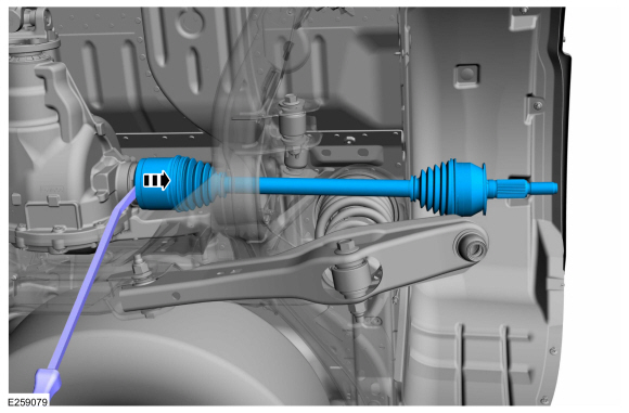
Using a pry bar, remove the halfshaft.
 |
-
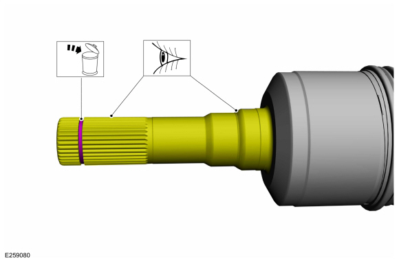
Inspect the inner halfshaft seal surface and splines for damage. Remove and discard the inner halfshaft circlip.
 |
-
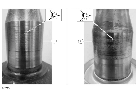
Inspect the inner CV housing.
-
Normal or acceptable wear.
-
Abnormal or excessive wear.
-
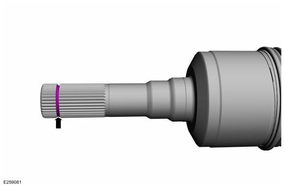
Normal or acceptable wear.
 |
Installation
-
NOTE: The halfshaft seal has to be replaced whenever the halfshaft is removed.
Replace the halfshaft seal.
Refer to: Rear Halfshaft Seal (205-02 Rear Drive Axle/Differential - Vehicles With: Ford 9.75 Inch Ring Gear, Removal and Installation).
-
Install a new inner halfshaft circlip.
 |
-
NOTICE: After insertion, pull the halfshaft inner end to make sure the circlip is locked.
NOTE: When seated correctly, the halfshaft retainer circlip can be felt as it snaps into the differential side gear groove.
Install the halfshaft until the halfshaft circlip is fully seated.
 |
-
Install the wheel knuckle.
Refer to: Wheel Knuckle (204-02 Rear Suspension, Removal and Installation).
-
Check and top off the rear differential fluid.
Refer to: Differential Fluid Level Check (205-02 Rear Drive Axle/Differential - Vehicles With: Ford 9.75 Inch Ring Gear, General Procedures).
 Outer Constant Velocity (CV) Joint Boot. Removal and Installation
Special Tool(s) /
General Equipment
Flat Headed Screw Driver
Boot Clamp Pliers
Removal
Remove the inner CV joint boot...
 Brake System
..
Other information:
Lincoln Navigator 2018-2026 Workshop Manual: Passive Anti-Theft System (PATS) - System Operation and Component Description. Description and Operation
System Operation System Diagram Item Description 1 IPC 2 Passive Key 3 RTM 4 GWM 5 GWM 6 PCM 7 PATS Center Antenna 8 Keyless Entry Rear Antenna 9 Ignition Switch 10 PATS Enable 11 BCM Netwo..
Lincoln Navigator 2018-2026 Workshop Manual: Side Airbag. Removal and Installation
Special Tool(s) / General Equipment Interior Trim Remover Removal WARNING: The following procedure prescribes critical repair steps required for correct restraint system operation during a crash. Follow all notes and steps carefully. Failure to follow step instructions may result in incorrect operation of the restraint system and increases the risk of ser..
Categories
- Manuals Home
- 4th Gen Lincoln Navigator Service Manual (2018 - 2026)
- Brake Service Mode Activation and Deactivation. General Procedures
- All Terrain Control Module (ATCM). Removal and Installation
- Head Up Display (HUD) Module Calibration. General Procedures
- Transmission Fluid Drain and Refill. General Procedures
- SYNC Module [APIM]. Removal and Installation
Wheel to Hub Runout Minimization. General Procedures
Check
NOTE: Wheel-to-hub optimization is important. Clearance between the wheel and hub can be used to offset or neutralize the Road Force® or run-out of the wheel and tire assembly. For every 0.001 inch of wheel-to-hub clearance, the Road Force® can be affected between 1 and 3 pounds depending on the tire stiffness.
NOTE: The example below illustrates how the clearance between the wheel and the hub can be used to offset the high spot of radial run-out or Road Force®. Following the procedure will make sure of the best optimization.
Position the wheel and tire assembly on the vehicle so that the high spot location of radial run-out or Road Force® is at the 6 o'clock position and