Lincoln Navigator: Engine Cooling - 3.5L EcoBoost (272kW/370PS) / Transmission Fluid Heater Coolant Control Valve. Removal and Installation
Special Tool(s) / General Equipment
| Hose Clamp Remover/Installer |
Removal
-


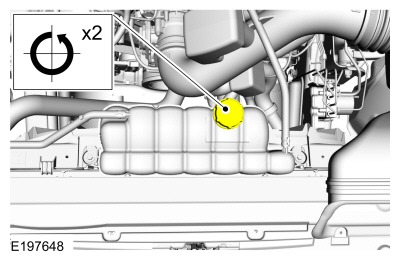
Release the cooling system pressure by slowly turning the degas bottle cap 2 turns. WARNING:
When releasing the cooling system pressure, cover the coolant expansion tank cap with a thick cloth.
WARNING:
When releasing the cooling system pressure, cover the coolant expansion tank cap with a thick cloth.
 |
-
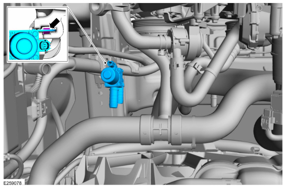
Remove the RH
CAC intake pipe.
Refer to: Charge Air Cooler (CAC) Intake Pipe (303-12 Intake Air Distribution and Filtering - 3.5L EcoBoost (272kW/370PS), Removal and Installation).
-
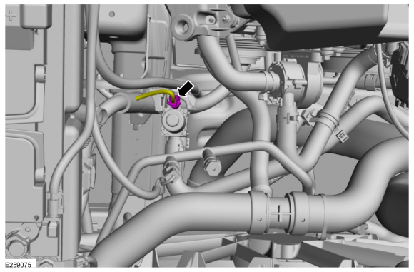
Disconnect the coolant control valve electrical connector.
 |
-
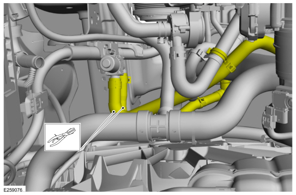
Clamp off the coolant control valve hoses.
 |
-
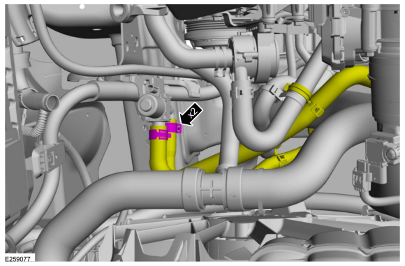
Release the clamps and disconnect the coolant hoses.
Use the General Equipment: Hose Clamp Remover/Installer
 |
-
Release the tab and remove the transmission fluid heater coolant control valve.
 |
Installation
-
To install, reverse the removal procedure.
-
Fill and bleed the cooling system without using a vacuum cooling system filler.
Refer to: Cooling System Draining, Vacuum Filling and Bleeding (303-03 Engine Cooling - 3.5L EcoBoost (272kW/370PS)) .
 Thermostat Housing. Removal and Installation
Special Tool(s) /
General Equipment
Hose Clamp Remover/Installer
Materials
Name
Specification
Motorcraft® Yellow Concentrated Antifreeze/CoolantVC-13-G
WSS-M97B57-A1
Motorcraft® Orange Concentrated Antifreeze/CoolantVC-3-B
WSS-M97B44-D
Removal
NOTE:
Removal steps in this procedure may contain installation details...

Other information:
Lincoln Navigator 2018-2026 Workshop Manual: Intake Air Flow. Diagnosis and Testing
Diagnostic Trouble Code (DTC) Chart Diagnostics in this manual assume a certain skill level and knowledge of Ford-specific diagnostic practices. REFER to: Diagnostic Methods (100-00 General Information, Description and Operation). Module DTC Description Action PCM P0111:00 Intake Air Temperature Sensor 1 Circuit Range/Performance (Bank 1): No Sub Type Information G..
Lincoln Navigator 2018-2026 Workshop Manual: Interior Lighting - System Operation and Component Description. Description and Operation
System Operation Overview The interior lighting system consists of: Courtesy lamps Demand lamps Ambient lighting The courtesy lamps subsystem consists of: Interior lamps Puddle lamps Door ajar switches (integrated into the door latches) Courtesy lamp switch (integrated into the front interior lamp) Cargo lamp C..
Categories
- Manuals Home
- 4th Gen Lincoln Navigator Service Manual (2018 - 2026)
- Transmission Fluid Drain and Refill. General Procedures
- Windshield Washer Pump. Removal and Installation
- Brake Service Mode Activation and Deactivation. General Procedures
- Body Control Module (BCM). Removal and Installation
- Front Bumper Cover. Removal and Installation
Wheel to Hub Runout Minimization. General Procedures
Check
NOTE: Wheel-to-hub optimization is important. Clearance between the wheel and hub can be used to offset or neutralize the Road Force® or run-out of the wheel and tire assembly. For every 0.001 inch of wheel-to-hub clearance, the Road Force® can be affected between 1 and 3 pounds depending on the tire stiffness.
NOTE: The example below illustrates how the clearance between the wheel and the hub can be used to offset the high spot of radial run-out or Road Force®. Following the procedure will make sure of the best optimization.
Position the wheel and tire assembly on the vehicle so that the high spot location of radial run-out or Road Force® is at the 6 o'clock position and