Lincoln Navigator: Side Panel Sheet Metal Repairs / Rocker Panel. Removal and Installation
Special Tool(s) / General Equipment
| 6.5 mm Drill Bit | |
| Spherical Cutter | |
| Self-Piercing Rivet (SPR) Remover/Installer | |
| Belt Sander | |
| Air Body Saw | |
| MIG/MAG Welding Equipment | |
| Locking Pliers |
Materials
| Name | Specification |
|---|---|
| Metal Bonding Adhesive TA-1, TA-1-B, 3M™ 08115, LORD Fusor® 108B, Henkel Teroson EP 5055 |
- |
| Seam Sealer TA-2-B, 3M™ 08308, LORD Fusor® 803DTM |
- |
| Flexible Foam Repair 3M™ 08463, LORD Fusor® 121 |
- |
Removal
NOTICE: Body side sectioning is prohibited within 50 mm of door hinge, door striker and restraints anchoring points.
NOTE: Aluminum body panels are highly receptive to heat transfer. With the extensive use of structural adhesives and non-structural sealers used in vehicle construction, the potential of heat transfer could impact adhesives and sealers in non-associated panels during the repair process. Many repairs areas that utilize structural adhesive may be separated after fastener removal by using a panel chisel along the joint/flange. Using heat not exceeding 425° F to loosen a bonded panel should only be done when all panels in the joint will be replaced and new adhesive applied.
NOTE: The rocker outer panel may be sectioned. The following assumes complete component replacement. Sectioning may be adjusted to meet repair requirement as long as door hinge, striker and restraints requirements are met.
NOTE: LH side shown, RH side similar.
-
Depower the SRS .
Refer to: Supplemental Restraint System (SRS) Depowering (501-20B Supplemental Restraint System, General Procedures).
-
Remove the front and rear door scuff plates and front and rear door opening weather strips.
-
Remove the front fender.
Refer to: Fender (501-02 Front End Body Panels, Removal and Installation).
-
Remove the front and rear doors.
Refer to: Front Door (501-03 Body Closures, Removal and Installation).
Refer to: Rear Door (501-03 Body Closures, Removal and Installation).
-
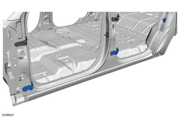
Remove the front and rear door lower hinges and striker.
 |
-
Verify the vehicle is dimensionally correct.
Refer to: Body and Frame (501-26 Body Repairs - Vehicle Specific Information and Tolerance Checks, Description and Operation).
-
Remove the quarter panel.
Refer to: Quarter Panel (501-30 Rear End Sheet Metal Repairs, Removal and Installation).
-
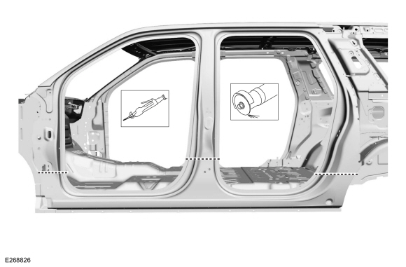
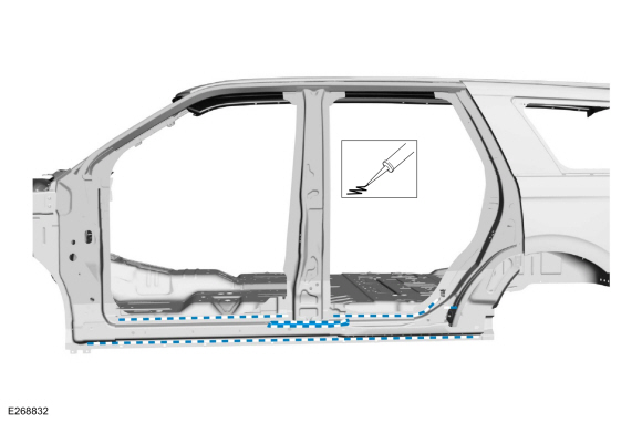
Carefully cut through the outer panel only as indicated.
Use the General Equipment: Air Body Saw
Use the General Equipment: Spherical Cutter
 |
-
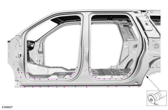
Remove the SPR fasteners and grind the lower wheelhouse flange.
Use the General Equipment: Self-Piercing Rivet (SPR) Remover/Installer
Use the General Equipment: Belt Sander
Use the General Equipment: Spherical Cutter
 |
-
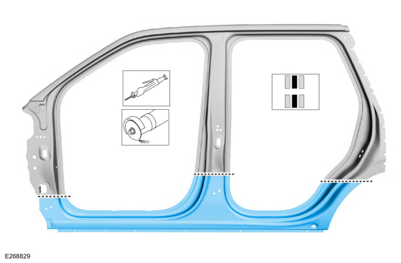
NOTE: Aluminum body panels are highly receptive to heat transfer. With the extensive use of structural adhesives and non-structural sealers used in vehicle construction, the potential of heat transfer could impact adhesives and sealers in non-associated panels during the repair process. Many repairs areas that utilize structural adhesive may be separated after fastener removal by using a panel chisel along the joint/flange. Using heat not exceeding 425° F to loosen a bonded panel should only be done when all panels in the joint will be replaced and new adhesive applied.
NOTE: Pay particular attention to NVH foam and baffle locations to aid in assembly.
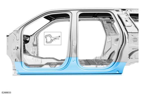
Break the adhesive bond and remove the rocker outer panel section.
 |
Installation
NOTICE: Body side sectioning is prohibited within 50 mm of door hinge, door striker and restraints anchoring points.
NOTE: SPR fasteners may not be placed directly over original SPR location. They must be placed adjacent to original location matching original quantity.
-
Cut a section from service panel to fit repair.
Use the General Equipment: Air Body Saw
Use the General Equipment: Spherical Cutter
 |
-
Sand using 80 grit sand paper to remove old adhesive and e-coat and clean.
 |
-
Sand using 80 grit sand paper to remove old adhesive and clean.
 |
-
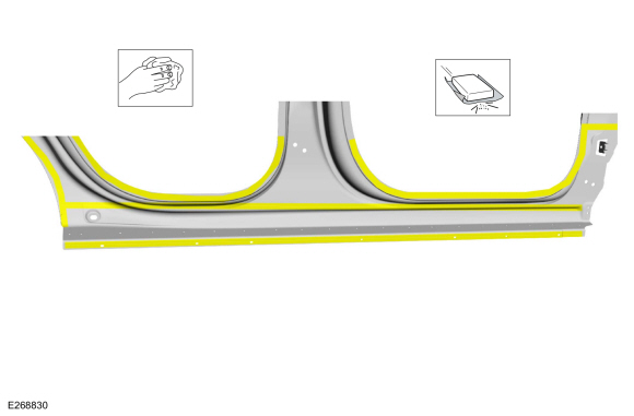
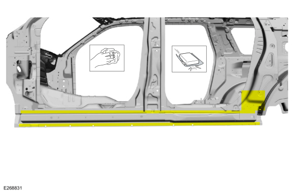
Apply adhesive and NVH foam to the mating surfaces as noted during removal.
Material: Flexible Foam Repair / 3M™ 08463, LORD Fusor® 121
Material: Metal Bonding Adhesive / TA-1, TA-1-B, 3M™ 08115, LORD Fusor® 108B, Henkel Teroson EP 5055
 |
-
NOTE: The use of a backer plate when creating butt weld joints will produce a stronger and more uniform repair.
In butt-weld areas:
Create a backer plate from an unused portion of the old body panel or service replacement panel and install on the vehicle at each sectioning joint.
Refer to: Joining Techniques (501-25 Body Repairs - General Information, General Procedures).
-
Install the rocker panel and clamp in position.
Use the General Equipment: Locking Pliers
 |
-
Drill for fasteners.
Use the General Equipment: 6.5 mm Drill Bit
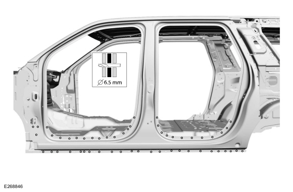 |
-
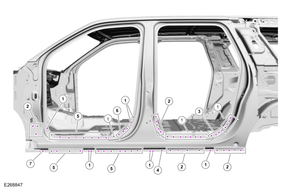
NOTE: SPR fasteners may not be placed directly over original SPR location. They must be placed adjacent to original location matching original quantity.
Install fasteners.Item SPR Number SPR Code Henrob® Mandrel Pro-Spot® Mandrel Blind Rivet Solid Rivet Rivnut® 1 W717752-S900 RB DP10-200/H SA-0400/SA-0402 W790377-S900 - 2 W717186-S900 EN DP11-220/H SA-0400/SA-0401 - W790376-S900 - 3 W717188-S900 PW DG10-200/H SA-0400/SA-0402 - W790376-S900 - 4 W708717-S900 AW DP11-200/H SA-0400/SA-0402 - W790377-S900 - 5 W717186-S900 EN DP11-200/H SA-0400/SA-0402 - W790377-S900 - 6 W717184-S900 QA DP10-200/H SA-0400/SA-0402 - W790377-S900 - 7 W710246-S900 BN DP10-200/H SA-0400/SA-0402 - W790377-S900
Refer to: Joining Techniques (501-25 Body Repairs - General Information, General Procedures).
Use the General Equipment: Self-Piercing Rivet (SPR) Remover/Installer
 |
-
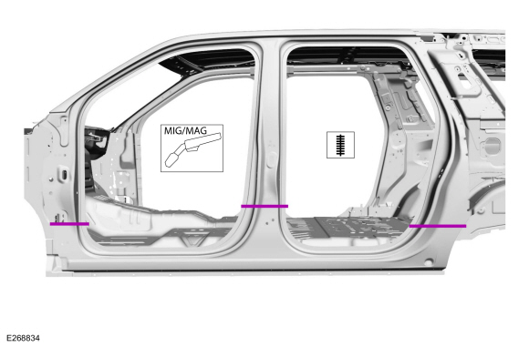
Complete joining of body side section to backing plates and seam weld at the sectioning joints.
Refer to: Joining Techniques (501-25 Body Repairs - General Information, General Procedures).
Use the General Equipment: MIG/MAG Welding Equipment
 |
-
Metal finish the repair using typical aluminum metal finishing techniques and a fiber-based body filler.
Refer to: Special Repair Considerations for Aluminum Repairs (501-25 Body Repairs - General Information, Description and Operation).
-
Seam Sealing:All areas must be sealed to production level.
Material: Seam Sealer / TA-2-B, 3M™ 08308, LORD Fusor® 803DTM
-
Install the quarter panel.
Refer to: Quarter Panel (501-30 Rear End Sheet Metal Repairs, Removal and Installation).
-
Refinish using a Ford approved paint system and typical refinishing techniques.
-
Install the front and rear door hinges and strikers.
-
Front door hinge.
Torque: 21 lb.ft (28 Nm)
-
Rear door hinge.
Torque: 22 lb.ft (30 Nm)
-
Door striker.
Torque: 18 lb.ft (25 Nm)
-
Front door hinge.
|
-
Install the front and rear doors.
Refer to: Front Door (501-03 Body Closures, Removal and Installation).
Refer to: Rear Door (501-03 Body Closures, Removal and Installation).
-
Install the front fender.
Refer to: Fender (501-02 Front End Body Panels, Removal and Installation).
-
Install the front and rear door scuff plates and front and rear door opening weather strips.
-
Align the front and rear doors.
Refer to: Front Door Alignment (501-03 Body Closures, General Procedures).
Refer to: Rear Door Alignment (501-03 Body Closures, General Procedures).

 Rocker Panel Inner Reinforcement. Removal and Installation
Special Tool(s) /
General Equipment
6.5 mm Drill Bit
Spherical Cutter
Grinder
Polydrive Bit Socket
Rivet Gun
Self-Piercing Rivet (SPR) Remover/Installer
Belt Sander
Hot Air Gun
Air Body Saw
MIG/MAG Welding Equipment
Locking Pliers
Materials
Name
Specification
Metal Bonding AdhesiveTA-1, ..
Other information:
Lincoln Navigator 2018-2026 Workshop Manual: Third Row Seat. Removal and Installation
Removal WARNING: The following procedure describes critical repair steps required for correct seat component installation. Follow all notes and steps carefully. Do not place any objects between the seat components and the body of the vehicle, nor any objects within a joint internal to the seat structure. Failure to follow step instructions may result in incorrect operatio..
Lincoln Navigator 2018-2026 Workshop Manual: Floor Panel Reinforcement. Removal and Installation
Special Tool(s) / General Equipment 6.5 mm Drill Bit Scraper for Straight Edges Self-Piercing Rivet (SPR) Remover/Installer Belt Sander Blind Rivet Gun Hot Air Gun Locking Pliers Materials Name Specification Metal Bonding AdhesiveTA-1, TA-1-B, 3M™ 08115, LORD Fusor® 108B, Henkel Teroson EP 5055 - ..
Categories
- Manuals Home
- 4th Gen Lincoln Navigator Service Manual (2018 - 2026)
- Front Bumper Cover. Removal and Installation
- Vehicle Dynamics Control Module (VDM). Removal and Installation
- Rear Bumper. Removal and Installation
- Windshield Washer Pump. Removal and Installation
- Telematics Control Unit (TCU) Module. Removal and Installation
Axle Tube Bearing. Removal and Installation
Special Tool(s) / General Equipment
 205-123
(T78P-1177-A)
205-123
(T78P-1177-A)
Installer, Axle Shaft Oil Seal
 308-047
(T77F-1102-A)
308-047
(T77F-1102-A)
Remover, Bearing Cup Slide Hammer