Lincoln Navigator: Side Panel Sheet Metal Repairs / Rocker Panel Inner Reinforcement. Removal and Installation
Special Tool(s) /
General Equipment
| 6.5 mm Drill Bit |
| Spherical Cutter |
| Grinder |
| Polydrive Bit Socket |
| Rivet Gun |
| Self-Piercing Rivet (SPR) Remover/Installer |
| Belt Sander |
| Hot Air Gun |
| Air Body Saw |
| MIG/MAG Welding Equipment |
| Locking Pliers |
Materials
| Name |
Specification |
Metal Bonding Adhesive
TA-1, TA-1-B, 3M™ 08115, LORD Fusor® 108B, Henkel Teroson EP 5055 |
-
|
Seam Sealer
TA-2-B, 3M™ 08308, LORD Fusor® 803DTM |
-
|
Flexible Foam Repair
3M™ 08463, LORD Fusor® 121 |
-
|
Removal
NOTICE:
Bodyside sectioning is prohibited within 50 mm of door hinge, door striker and restraints anchoring points.
NOTE:
SPR fasteners may not be placed directly over original SPR location.
They must be placed adjacent to original location matching original
quantity.
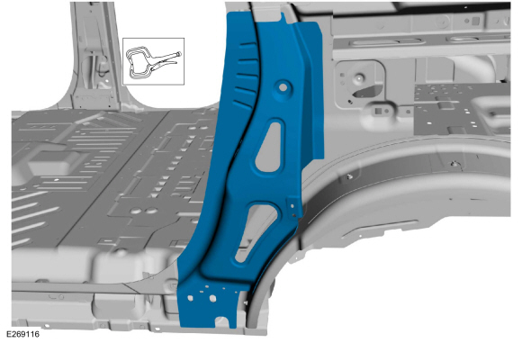
NOTE:
The rocker panel inner reinforcement is a two-piece
component consisting of a front and rear sections which can be service
individually. The front portion is an extrusion casting and may not be sectioned.
The rear portion only may be sectioned using a backer plate, adhesive
and blind rivets. The following procedure assumes full component
replacement, adjust to meet repair needs.
NOTE:
Aluminum body panels are highly receptive to heat transfer.
With the extensive use of structural adhesives and non-structural
sealers used in vehicle construction, the potential of heat transfer
could impact adhesives and sealers in non-associated panels during the
repair process. Many repairs areas that utilize structural adhesive may
be separated after fastener removal by using a panel chisel along the
joint/flange. Using heat not exceeding 425° F to loosen a bonded panel
should only be done when all panels in the joint will be replaced and
new adhesive applied.
NOTE:
Flow Drill Screws (FDS) are not to be reused. Remove and discard.
NOTE:
LH side shown, RH side similar.
-
Depower the SRS .
Refer to: Supplemental Restraint System (SRS) Depowering (501-20B Supplemental Restraint System, General Procedures).
-
Remove the fender.
Refer to: Fender (501-02 Front End Body Panels, Removal and Installation).
-
Remove the front and rear door scuff plates and front and rear door opening weather strips.
-
Verify the vehicle is dimensionally correct.
Refer to: Body and Frame (501-26 Body Repairs - Vehicle Specific Information and Tolerance Checks, Description and Operation).
-
Remove the front and rear doors.
Refer to: Front Door (501-03 Body Closures, Removal and Installation).
Refer to: Rear Door (501-03 Body Closures, Removal and Installation).
-
Remove the quarter panel.
Refer to: Quarter Panel (501-30 Rear End Sheet Metal Repairs, Removal and Installation).
-
Remove the front and rear door hinges and strikers.
-
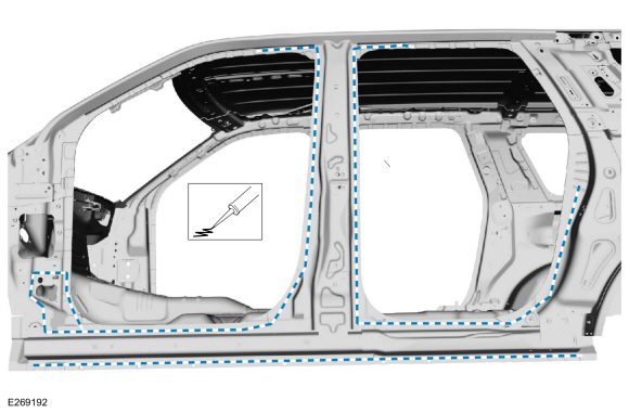
Cut through the outer layer only of the bodyside panel as indicated.
Use the General Equipment: Air Body Saw
Use the General Equipment: Spherical Cutter
-
NOTE:
Make note of fastener quantity during removal.
Remove the rivet fasteners and grind the lower wheelhouse flange.
Use the General Equipment: Grinder
Use the General Equipment: Belt Sander
-
NOTE:
Pay particular attention to NVH foam locations when removing outer panel.
Remove the outer bodyside section.
-
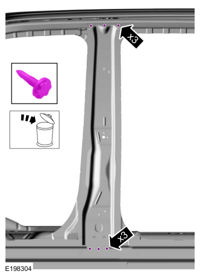
Remove and discard the B-pillar reinforcement FDS fasteners.
Use the General Equipment: Polydrive Bit Socket
-
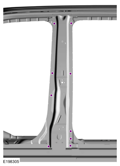
Remove the SPR fasteners in the B-pillar reinforcement.
Use the General Equipment: Self-Piercing Rivet (SPR) Remover/Installer
Use the General Equipment: Belt Sander
-
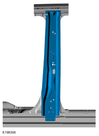
Break the adhesive bond and remove the B-pillar reinforcement.
-
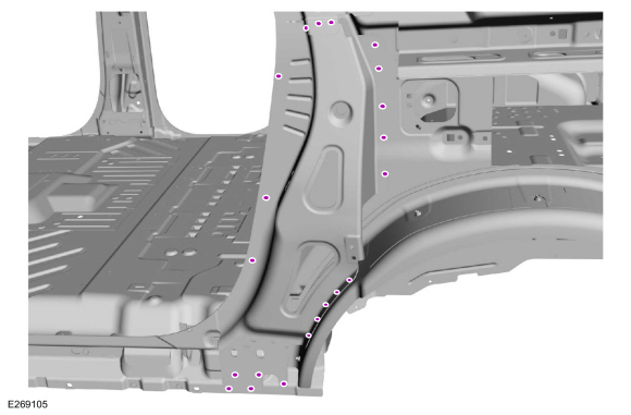
Remove the C-pillar lower reinforcement fasteners.
Use the General Equipment: Self-Piercing Rivet (SPR) Remover/Installer
Use the General Equipment: Belt Sander
-
NOTE:
Long wheelbase (LWB) shown, short wheelbase (SWB) similar.
Note NVH foam locations when removing panel.
Break the adhesive bond and remove the reinforcement.
Use the General Equipment: Hot Air Gun
-
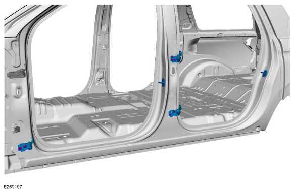
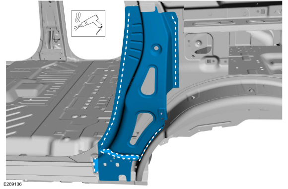
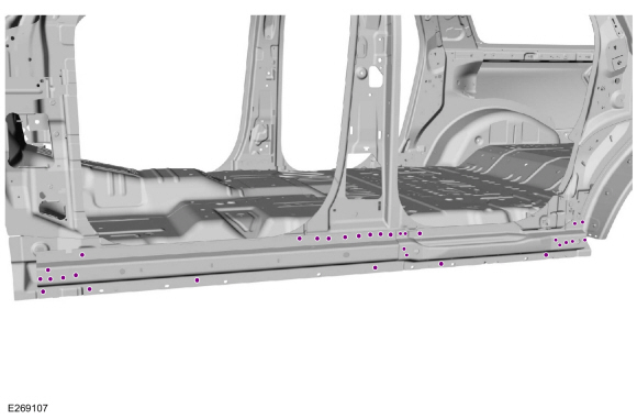
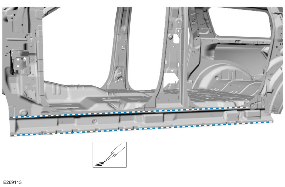
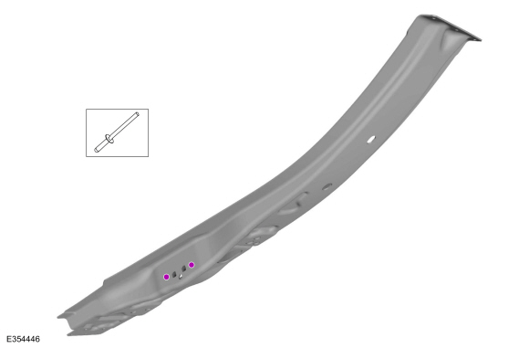
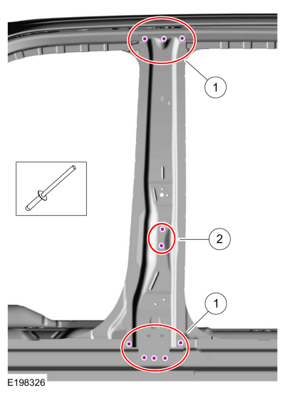
Remove the SPR fasteners in the front and rear rocker panel inner reinforcement.
Use the General Equipment: Self-Piercing Rivet (SPR) Remover/Installer
Use the General Equipment: Belt Sander
-
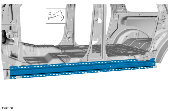
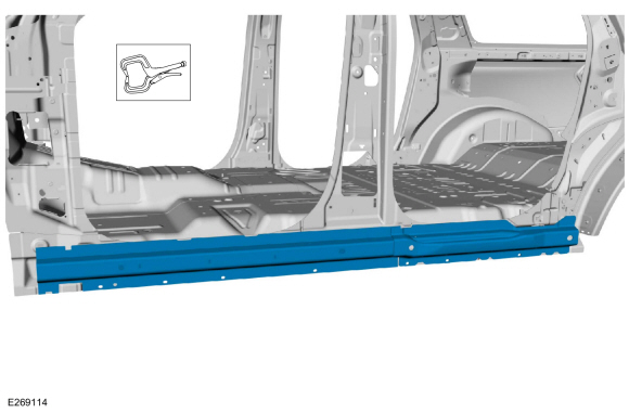
Break the adhesive bond and remove the rocker panel inner reinforcement(s).
Use the General Equipment: Hot Air Gun
Installation
NOTICE:
Bodyside sectioning is prohibited within 50 mm of door hinge, door striker and restraints anchoring points.
NOTE:
SPR fasteners may not be placed directly over original SPR location.
They must be placed adjacent to original location matching original
quantity.
NOTE:
Left hand (LH) side shown, right hand (RH) side similar.
-
80-120 Grit Sand Paper
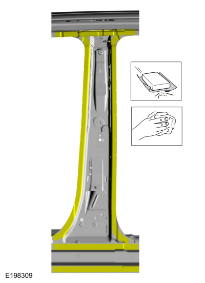
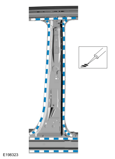
Sand to remove old adhesive, paint and clean the inner B-pillar reinforcement mating surfaces.
-
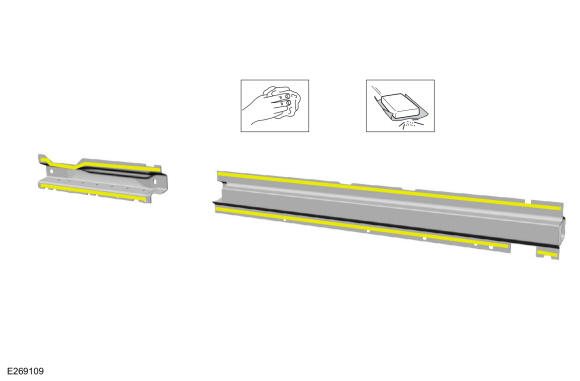
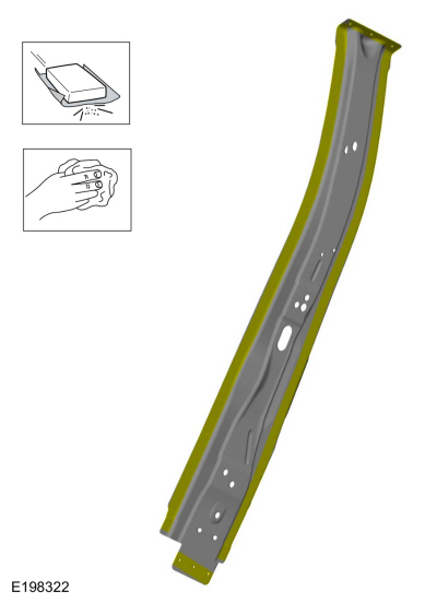
80-120 Grit Sand Paper
Sand to remove the old adhesive, paint and clean the inner rocker panel reinforcement mating surfaces.
-
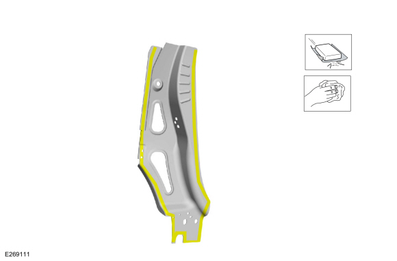
80-120 Grit Sand Paper:
Sand to remove e-coat from the front rocker panel reinforcements and clean.
-
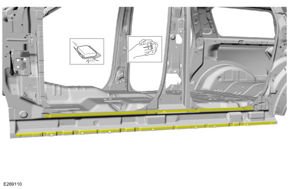
Apply adhesive to the rocker panel inner reinforcement mating surface.
Material: Metal Bonding Adhesive
/ TA-1, TA-1-B, 3M™ 08115, LORD Fusor® 108B, Henkel Teroson EP 5055
-
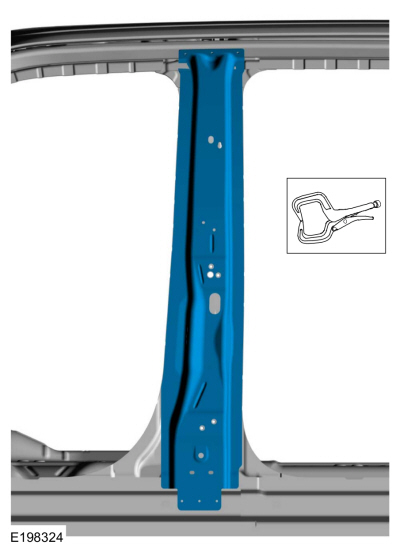
Install, properly position and clamp the rocker panel inner reinforcements.
Use the General Equipment: Locking Pliers
-
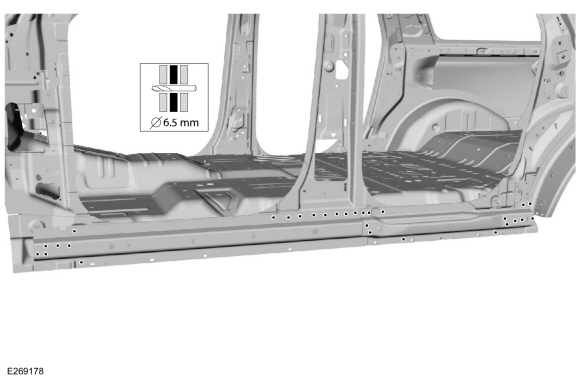
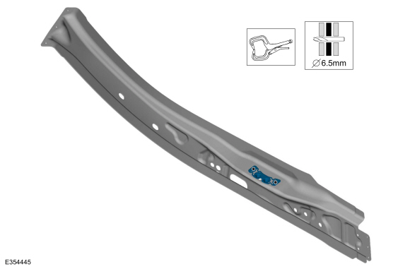
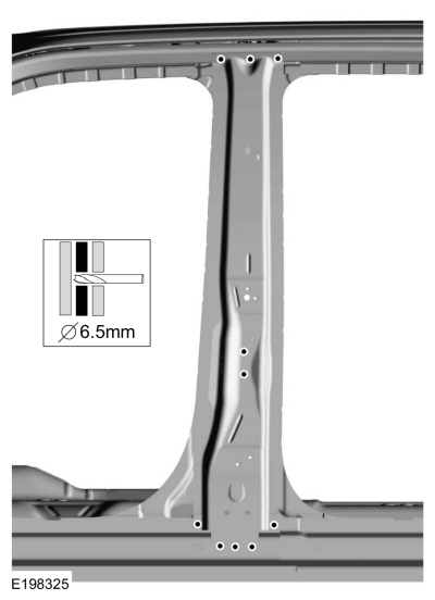
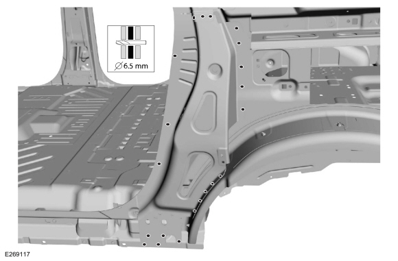
Drill for fasteners.
Use the General Equipment: 6.5 mm Drill Bit
-
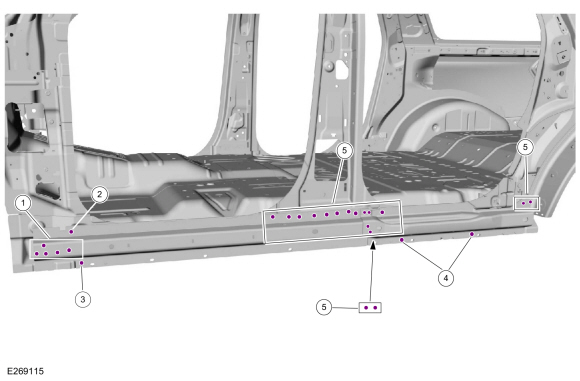
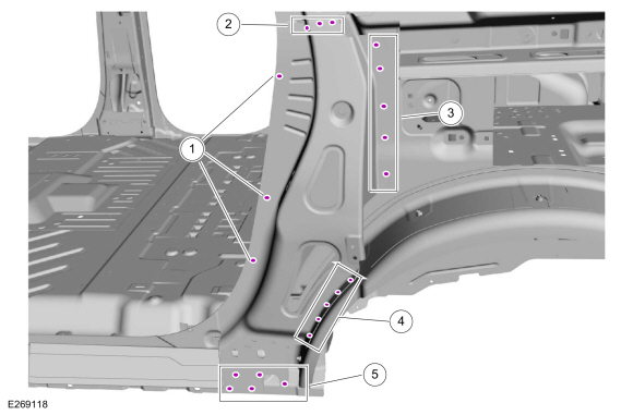
Install fasteners.
|
Item
|
SPR Number
|
SPR Code
|
Henrob®, Car-O-Liner ®, CMO®, Chief®, Spanesi®, Wielander and Schill® Mandrel
|
Pro-Spot® Mandrel
|
Blind Rivet
|
Solid Rivet
|
Rivnut®
|
|
1
|
-
|
-
|
-
|
-
|
W702554-S900C
|
-
|
-
|
|
2
|
-
|
-
|
-
|
-
|
W702512-S900C
|
-
|
-
|
|
3
|
W710246-S900
|
BN
|
DP10-200/H
|
SA-0400/SA-0401
|
-
|
W790377-S900
|
-
|
|
4
|
W708713-S900
|
AS
|
DZ09-025/H
|
SA-0400/SA-0401
|
-
|
W790377-S900
|
-
|
|
5
|
-
|
-
|
-
|
-
|
W708777-S900C
|
-
|
-
|
Use the General Equipment: Rivet Gun
-
80-120 grit sand paper.
Sand to remove e-coat from the B-pillar reinforcement mating surfaces and clean.
-
Install, properly position, clamp and drill the striker plate reinforcement.
Use the General Equipment: Locking Pliers
Use the General Equipment: 6.5 mm Drill Bit
-
Install the fasteners.
|
Item
|
SPR Number
|
SPR Code
|
Henrob®, Car-O-Liner ®, CMO®, Chief®, Spanesi®, Wielander and Schill® Mandrel
|
Pro-Spot® Mandrel
|
Blind Rivet
|
Solid Rivet
|
Rivnut®
|
|
1
|
-
|
-
|
-
|
-
|
W702512-S900C
|
-
|
-
|
Use the General Equipment: Rivet Gun
-
Apply adhesive to the B-pillar mating surfaces.
Material: Metal Bonding Adhesive
/ TA-1, TA-1-B, 3M™ 08115, LORD Fusor® 108B, Henkel Teroson EP 5055
-
Install, properly position and clamp the B-pillar reinforcement.
Use the General Equipment: Locking Pliers
-
Drill for fasteners.
Use the General Equipment: 6.5 mm Drill Bit
-
Install blind rivet fasteners in B-pillar reinforcement.
|
Item
|
SPR Number
|
SPR Code
|
Henrob®, Car-O-Liner ®, CMO®, Chief®, Spanesi®, Wielander and Schill® Mandrel
|
Pro-Spot® Mandrel
|
Blind Rivet
|
Solid Rivet
|
Rivnut®
|
|
1
|
-
|
-
|
-
|
-
|
W708777-S900C
|
-
|
-
|
|
2
|
-
|
-
|
-
|
-
|
W702512-S900C
|
-
|
-
|
Use the General Equipment: Rivet Gun
-
80-120 Grit Sand Paper
Sand and clean the C-pillar reinforcement flanges.
-
80-120 Grit Sand Paper
Sand and clean the C-pillar mating surface.
-
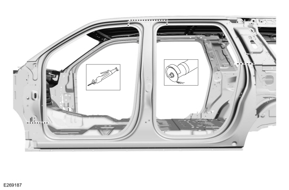
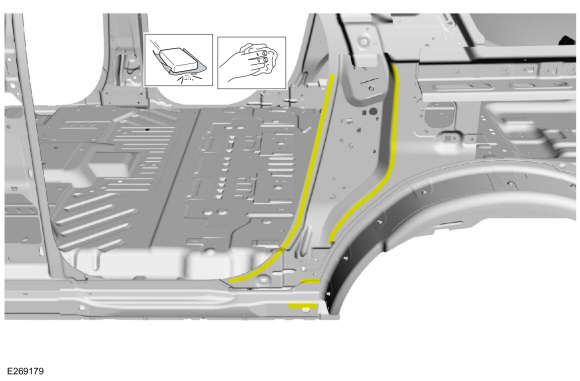
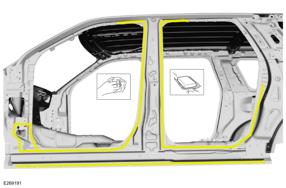
Apply adhesive and NVH foam to the C-pillar mating surface as indicated.
Material: Metal Bonding Adhesive
/ TA-1, TA-1-B, 3M™ 08115, LORD Fusor® 108B, Henkel Teroson EP 5055
Material: Flexible Foam Repair
/ 3M™ 08463, LORD Fusor® 121
-
Install, properly position and clamp the C-pillar reinforcement.
-
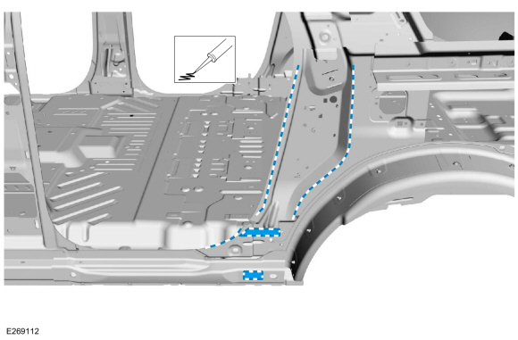
Drill for fasteners.
Use the General Equipment: 6.5 mm Drill Bit
-
NOTE:
SPR fasteners may be replaced with solid rivets or blind rivet fasteners after enlarging hole to 6.5 mm.
NOTE:
SPR
fasteners may not be placed directly over original location. They must
equal original quantity and be placed adjacent to original location.
NOTE:
Long wheelbase (LWB) shown, standard wheelbase (SWB) similar.
|
Item
|
SPR Number
|
SPR Code
|
Henrob®, Car-O-Liner ®, CMO®, Chief®, Spanesi®, Wielander and Schill® Mandrel
|
Pro-Spot® Mandrel
|
Blind Rivet
|
Solid Rivet
|
Rivnut®
|
|
1
|
W712218-S900C
|
DB
|
DZ09-025/H
|
SA-0400/SA-0401
|
W702512-S900C
|
W790376-S900C
|
-
|
|
2
|
-
|
-
|
-
|
-
|
W702512-S900C
|
-
|
-
|
|
3
|
-
|
-
|
-
|
-
|
W702512-S900C
|
-
|
-
|
|
4
|
-
|
-
|
|
-
|
W707638-S900C
|
-
|
-
|
|
5
|
-
|
-
|
-
|
-
|
W08777-S900C
|
-
|
-
|
-
80-120 Grit Sand Paper:
Sand to remove old adhesive, paint, e-coat and clean.
-
NOTE:
The use of a backer plate sectioning joints will produce a stronger and more uniform repair.
In sectioning joint areas: Create a backer
plate from an unused portion of the old body panel or service
replacement panel and install on the vehicle at each sectioning joint.
Refer to: Joining Techniques (501-25 Body Repairs - General Information, General Procedures).
-
Apply adhesive.
Material: Metal Bonding Adhesive
/ TA-1, TA-1-B, 3M™ 08115, LORD Fusor® 108B, Henkel Teroson EP 5055
-
Complete the backer plate attachment at all sectioning joints.
Refer to: Joining Techniques (501-25 Body Repairs - General Information, General Procedures).
-
Install, properly position and clamp the bodyside section.
Use the General Equipment: Locking Pliers
 |
|
-
NOTE:
SPR fasteners may be replaced with solid rivets or blind rivet fasteners after enlarging hole to 6.5 mm.
NOTE:
SPR
fasteners may not be placed directly over original location. They must
equal original quantity and be placed adjacent to original location.
Install the fasteners.
|
Item
|
SPR Number
|
SPR Code
|
Henrob®, Car-O-Liner ®, CMO®, Chief®, Spanesi®, Wielander and Schill® Mandrel
|
Pro-Spot® Mandrel
|
Blind Rivet
|
Solid Rivet
|
Rivnut®
|
|
1
|
W708713-S900
|
AS
|
DZ09-025/H
|
SA-0400/SA-0401
|
-
|
W790376-S900
|
-
|
|
2
|
W717184-S900
|
QA
|
DP10-200/H
|
SA-0400/SA-0402
|
-
|
W790377-S900
|
-
|
|
3
|
W717186-S900
|
EN
|
DP11-200/H
|
SA-0400/SA-0402
|
-
|
W790377-S900
|
-
|
|
4
|
W708717-S900
|
AW
|
DP11-200/H
|
SA-0400/SA-0402
|
-
|
W790377-S900
|
-
|
|
5
|
W710246-S900
|
BN
|
DP10-200/H
|
SA-0400/SA-0402
|
-
|
W790377-S900
|
-
|
|
6
|
W708717-S900
|
AW
|
DG10-220/H
|
SA-0400/SA-0402
|
-
|
W790377-S900
|
-
|
|
7
|
W717186-S900
|
EN
|
DG11-220/H
|
SA-0400/SA-0402
|
-
|
W790377-S900
|
-
|
Use the General Equipment: Self-Piercing Rivet (SPR) Remover/Installer
 |
|
-
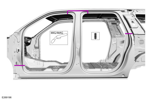
Seam weld the sectioning joints with a welder set up for aluminum welding.
Refer to: Special Repair Considerations for Aluminum Repairs (501-25
Body Repairs - General Information, Description and Operation).
Refer to: Welding Precautions (501-25 Body Repairs - General Information, General Procedures).
Use the General Equipment: MIG/MAG Welding Equipment
-
Metal finish the repair using typical aluminum metal finishing techniques and a fiber-based body filler.
Refer to: Special Repair Considerations for Aluminum Repairs (501-25
Body Repairs - General Information, Description and Operation).
Refer to: Joining Techniques (501-25 Body Repairs - General Information, General Procedures).
-
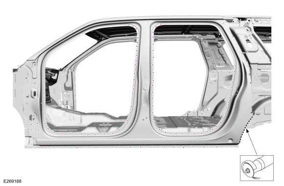
Seam Sealing:
All areas must be sealed to production level.
Material: Seam Sealer
/ TA-2-B, 3M™ 08308, LORD Fusor® 803DTM
-
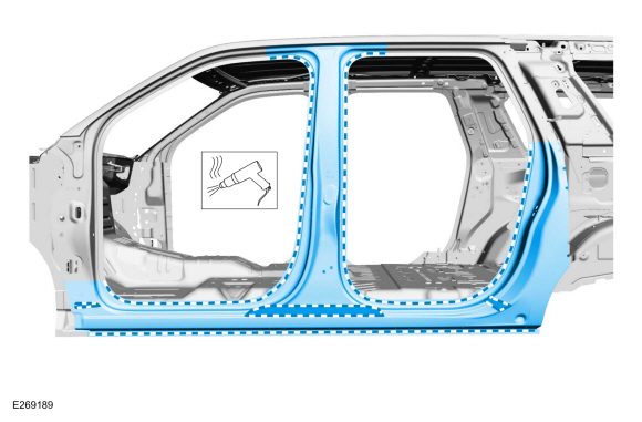
Refinish the repair area using a Ford approved paint system.
-
Install the quarter panel.
Refer to: Quarter Panel (501-30 Rear End Sheet Metal Repairs, Removal and Installation).
-
Install the fender.
Refer to: Fender (501-02 Front End Body Panels, Removal and Installation).
-
Install the door hinges and strikers.
Torque:
Front door hinge :
21 lb.ft (28 Nm)
Rear door hinges :
22 lb.ft (30 Nm)
Strikers :
18 lb.ft (25 Nm)
-
Install the front and rear doors.
Refer to: Front Door (501-03 Body Closures, Removal and Installation).
Refer to: Rear Door (501-03 Body Closures, Removal and Installation).
-
Align the front and rear doors as required.
Refer to: Front Door Alignment (501-03 Body Closures, General Procedures).
Refer to: Rear Door Alignment (501-03 Body Closures, General Procedures).
-
Install the front and rear door scuff plates and front and rear door opening weather strips.
-
Repower the SRS .
Refer to: Supplemental Restraint System (SRS) Repowering (501-20B Supplemental Restraint System, General Procedures).
Other information:
Activation
WARNING:
Shifting the transfer case to its neutral position for
neutral flat towing may allow the vehicle to be able to roll even if the
transmission is in park (P). Make sure the foot brake is depressed and
the vehicle is in a secure and safe position while the transfer case is
being shifted to its neutral position. Failure to follow this
instruction may resul..
Removal
NOTE:
Removal steps in this procedure may contain installation details.
NOTE:
High series heated steering wheel shown, all others similar.
NOTE:
Make sure the wheels are in the straight ahead position.
Remove the driver airbag.
Refer to: Driver Airbag (501-20B Supplemental Restraint System, Removal and Installation).
Disconne..