Lincoln Navigator: Handles, Locks, Latches and Entry Systems / Rear Door Latch. Removal and Installation
Removal
NOTE: LH side shown, RH side similar.
NOTE: Removal steps in this procedure may contain installation details.
-
Remove the rear door trim panel.
Refer to: Rear Door Trim Panel (501-05 Interior Trim and Ornamentation, Removal and Installation).
-
Remove the exterior rear door handle.
Refer to: Exterior Rear Door Handle (501-14 Handles, Locks, Latches and Entry Systems) .
-
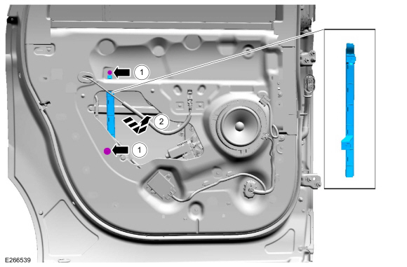
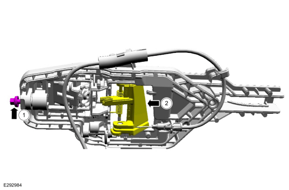
Remove the aft rear door glass run and bracket.
-
Remove the bolts from the aft rear door glass run and bracket.
Torque: 71 lb.in (8 Nm)
-
Remove the aft rear door glass run and bracket.
-
Remove the bolts from the aft rear door glass run and bracket.
 |
-
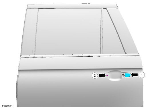
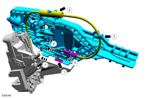
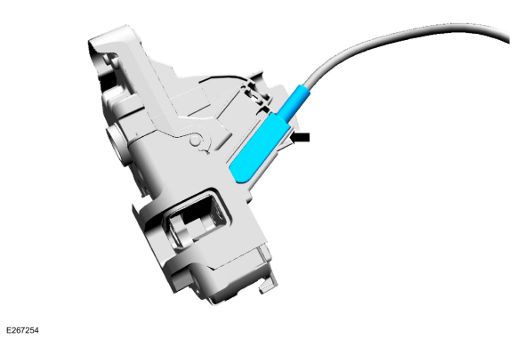
Remove the exterior rear door handle plug and the exterior rear door handle reinforcement screw.
-
Remove the exterior rear door handle plug.
-
Remove the screw from the exterior rear door handle reinforcement.
Torque: 62 lb.in (7 Nm)
-
Remove the exterior rear door handle plug.
 |
-
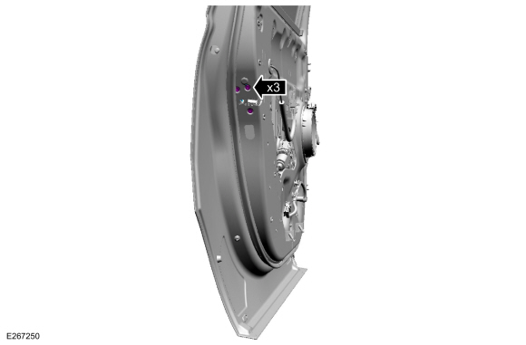
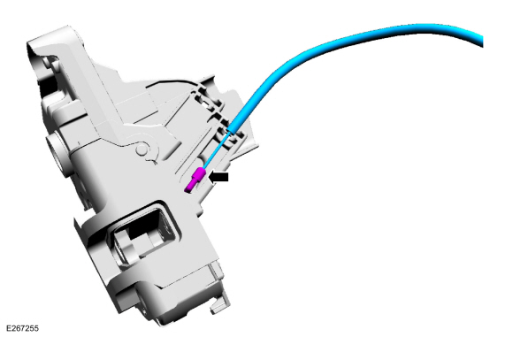
Remove the rear door latch bolts.
Torque: 71 lb.in (8 Nm)
 |
-
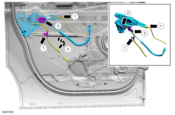
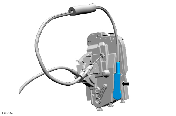
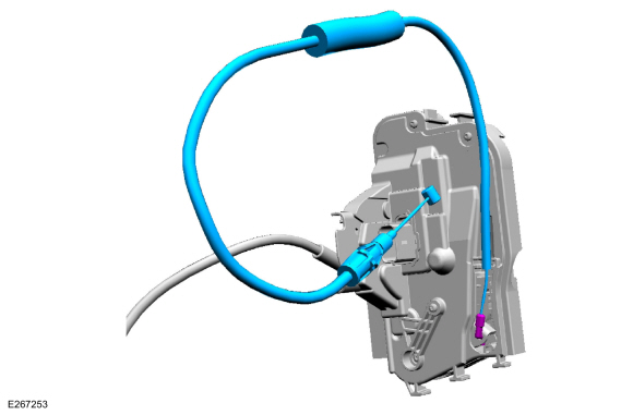
Remove the rear door latch.
-
Disconnect the wiring harness routing clip and
position the exterior rear door handle reinforcement wiring harness
aside.
-
Disconnect the rear door latch electrical connector.
-
Route the interior rear door handle cable through the inner door.
-
Remove the rear door latch.
-
Disconnect the wiring harness routing clip and
position the exterior rear door handle reinforcement wiring harness
aside.
 |
-
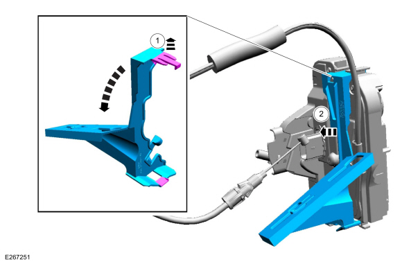
NOTE: This step is only necessary when installing a new component.
Release the cable tension by turning the release screw until the handle lever releases from the stop.
-
Turn the release screw until the handle lever releases from the stop.
-
Release the handle lever from the stop.
-
Turn the release screw until the handle lever releases from the stop.
 |
-
NOTE: This step is only necessary when installing a new component.
Remove the exterior front door handle reinforcement.
-
Press the locking tab down and detach the exterior front door handle reinforcement.
-
Remove the cable from the routing clip.
-
Remove the cable from the routing clip.
-
Remove the cable eyelet from the lever.
-
Detach the cable from the exterior front door handle reinforcement.
-
Press the locking tab down and detach the exterior front door handle reinforcement.
 |
-
NOTE: This step is only necessary when installing a new component.
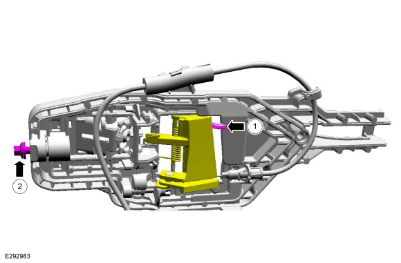
Remove the rear door latch bracket.
-
Release the retaining tabs on the rear door latch bracket.
-
Remove the rear door latch bracket.
-
Release the retaining tabs on the rear door latch bracket.
 |
-
NOTE: This step is only necessary when installing a new component.
Remove the exterior rear door handle reinforcement to rear door latch cable access cover.
 |
-
NOTE: This step is only necessary when installing a new component.
Remove the exterior rear door handle reinforcement to rear door latch cable.
 |
-
NOTE: This step is only necessary when installing a new component.
Remove the interior rear door handle cable access cover.
 |
-
NOTE: This step is only necessary when installing a new component.
Remove the interior rear door handle cable.
 |
Installation
-
To install, reverse the removal procedure.
-
NOTE: This step is only necessary when installing a new component.
NOTE: This step must be done correctly or the exterior door handle will not engage the lever on installation.
Position the exterior rear door handle reinforcement in the service position.
-
While keeping tension on the cable and holding the handle lever in the engaged position against the stop.
-
Turn the release screw until the handle lever is positioned against the stop.
-
While keeping tension on the cable and holding the handle lever in the engaged position against the stop.
 |
-
Carry out the power door window initialization.
Refer to: Power Door Window Initialization (501-11 Glass, Frames and Mechanisms, General Procedures).
 Liftgate Window Latch. Removal and Installation
Removal
Remove the liftgate trim panel.
Refer to: Liftgate Trim Panel (501-05 Interior Trim and Ornamentation, Removal and Installation)...

Other information:
Lincoln Navigator 2018-2026 Workshop Manual: Wheel and Tire. Removal and Installation
Materials Name Specification Motorcraft® High Temperature Nickel Anti-Seize LubricantXL-2 - Removal With the vehicle in NEUTRAL, position it on a hoist. Refer to: Jacking and Lifting (100-02 Jacking and Lifting, Description and Operation). If equipped. Remove the wheel cap. NOT..
Lincoln Navigator 2018-2026 Workshop Manual: Interior Camera System - System Operation and Component Description. Description and Operation
System Operation System Operation Overview The interior camera system works with the active drive assist system to continuously observe the driver when the active drive assist system is in use. The interior camera system observes the drivers eyes and head position to determine if the driver is attentive or distracted. The interior camera system consists of: Driver sid..
Categories
- Manuals Home
- 4th Gen Lincoln Navigator Service Manual (2018 - 2026)
- Neutral Flat Tow Activation and Deactivation. General Procedures
- Vehicle Dynamics Control Module (VDM). Removal and Installation
- Remote Function Actuator (RFA) Module. Removal and Installation
- Brake Service Mode Activation and Deactivation. General Procedures
- Windshield Washer Pump. Removal and Installation
Rear Camber Adjustment. General Procedures
Special Tool(s) / General Equipment
Wheel Alignment SystemActivation
NOTICE: Suspension fasteners are critical parts that affect the performance of vital components and systems. Failure of these fasteners may result in major service expense. Use the same or equivalent parts if replacement is necessary. Do not use a replacement part of lesser quality or substitute design. Tighten fasteners as specified.
Using alignment equipment and the manufacturer's instructions, measure the rear camber.Use the General Equipment: Wheel Alignment System