Lincoln Navigator: Handles, Locks, Latches and Entry Systems / Liftgate Window Latch. Removal and Installation
Removal
-
Remove the liftgate trim panel.
Refer to: Liftgate Trim Panel (501-05 Interior Trim and Ornamentation, Removal and Installation).
-
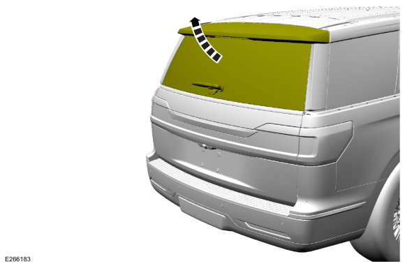
Open the liftgate window glass.
 |
-
Remove the liftgate window latch.
-
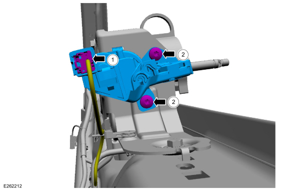
Disconnect the liftgate window latch electrical connector.
-
Remove the bolts and the liftgate window latch.
-
Disconnect the liftgate window latch electrical connector.
 |
Installation
-
To install, reverse the removal procedure.
 Liftgate Window Glass Release Switch. Removal and Installation
Removal
Remove the reversing lamp assembly.
Refer to: Reversing Lamp (417-01 Exterior Lighting, Removal and Installation).
Disconnect the coaxial cable connector...
 Rear Door Latch. Removal and Installation
Removal
NOTE:
LH side shown, RH side similar.
NOTE:
Removal steps in this procedure may contain installation details.
Remove the rear door trim panel...
Other information:
Lincoln Navigator 2018-2026 Workshop Manual: Frame Members-Rear Frame Section. Removal and Installation
Special Tool(s) / General Equipment Grinder MIG/MAG Welding Equipment Removal Restore the vehicle to manufacturer's dimensions. Refer to: Body and Frame (501-26 Body Repairs - Vehicle Specific Information and Tolerance Checks, Description and Operation)...
Lincoln Navigator 2018-2026 Workshop Manual: Parking Brake - Component Location. Description and Operation
Item Description 1 ABS module 2 Parking brake switch 3 Parking brake actuator motor (2 required) ..
Categories
- Manuals Home
- 4th Gen Lincoln Navigator Service Manual (2018 - 2026)
- Remote Function Actuator (RFA) Module. Removal and Installation
- Windshield Washer Pump. Removal and Installation
- Vehicle Dynamics Control Module (VDM). Removal and Installation
- Neutral Flat Tow Activation and Deactivation. General Procedures
- Body Control Module (BCM). Removal and Installation
Wheel to Hub Runout Minimization. General Procedures
Check
NOTE: Wheel-to-hub optimization is important. Clearance between the wheel and hub can be used to offset or neutralize the Road Force® or run-out of the wheel and tire assembly. For every 0.001 inch of wheel-to-hub clearance, the Road Force® can be affected between 1 and 3 pounds depending on the tire stiffness.
NOTE: The example below illustrates how the clearance between the wheel and the hub can be used to offset the high spot of radial run-out or Road Force®. Following the procedure will make sure of the best optimization.
Position the wheel and tire assembly on the vehicle so that the high spot location of radial run-out or Road Force® is at the 6 o'clock position and