Lincoln Navigator: Voltage Converter/Inverter / Alternating Current (AC) Power Outlet Socket. Removal and Installation
Special Tool(s) / General Equipment
| Interior Trim Remover |
Removal
 WARNING:
Disconnect the 12 volt battery before servicing the direct
current to alternating current (DC-AC) inverter or alternating current
(AC) powerpoint to prevent the risk of high voltage shock. Failure to
follow this instruction may result in serious personal injury.
WARNING:
Disconnect the 12 volt battery before servicing the direct
current to alternating current (DC-AC) inverter or alternating current
(AC) powerpoint to prevent the risk of high voltage shock. Failure to
follow this instruction may result in serious personal injury.
-
Disconnect the negative battery cable from the battery.
Refer to: Battery Disconnect and Connect (414-01 Battery, Mounting and Cables, General Procedures).
-
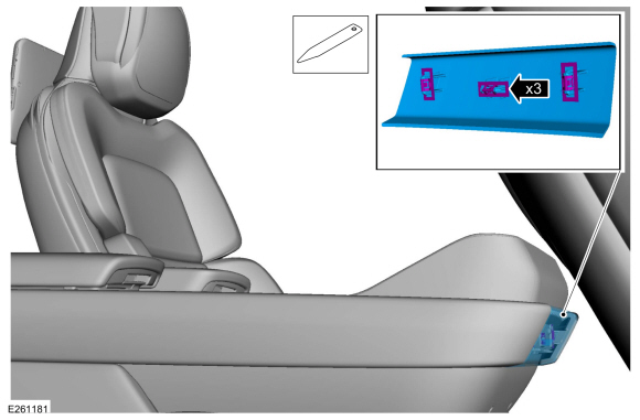
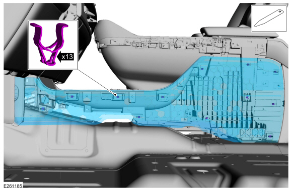
Release the clips and remove the front floor console trim panel.
Use the General Equipment: Interior Trim Remover
 |
-
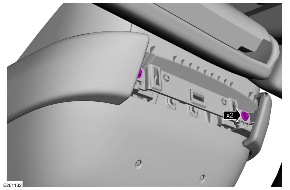
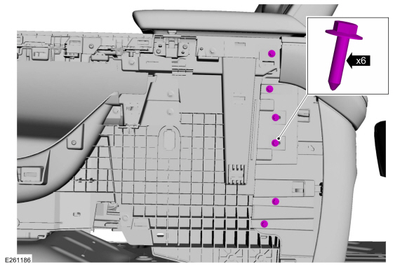
Remove the bolts.
 |
-
Position the floor console armrest.
 |
-
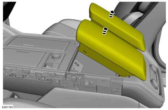
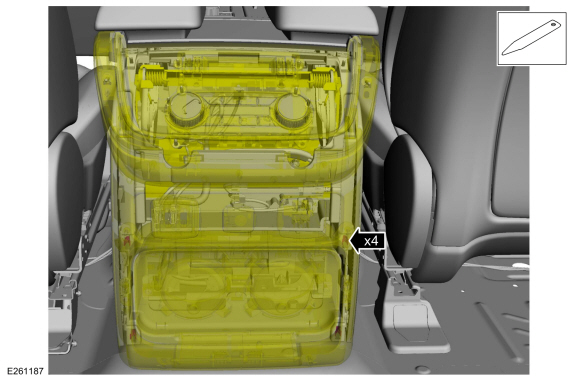
On both sides
Release the clips and remove the floor console finish panel.
Use the General Equipment: Interior Trim Remover
 |
-
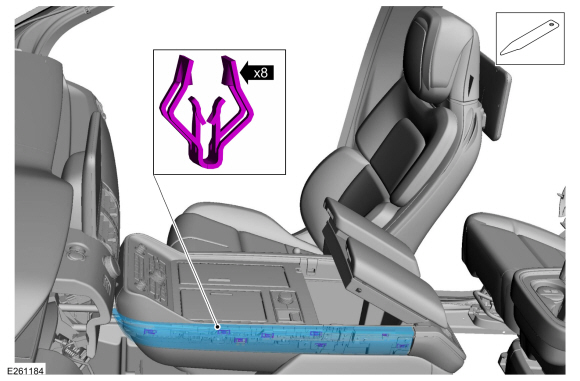
On both sides
Release the clips and remove the floor console side trim panel.
Use the General Equipment: Interior Trim Remover
 |
-
Remove the bolts.
 |
-
Release the clips and position the floor console rear trim panel out.
Use the General Equipment: Interior Trim Remover
 |
-
Disconnect the electrical connectors and remove the floor console rear trim panel.
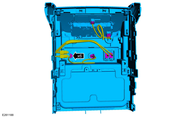 |
-
Press the retainers inward and remove the AC power outlet socket.
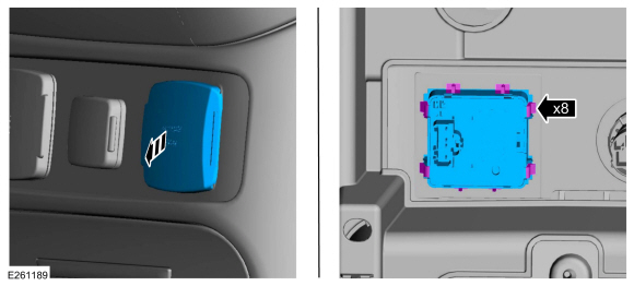 |
Installation
-
To install, reverse the removal procedure.
 Direct Current/Direct Current (DC/DC) Converter Control Module. Diagnosis and Testing
Diagnostics in this manual assume a certain skill level and knowledge of Ford-specific diagnostic practices. REFER to: Diagnostic Methods (100-00 General Information, Description and Operation)...
 Direct Current/Alternating Current (DC/AC) Inverter. Removal and Installation
Removal
WARNING:
Disconnect the 12 volt battery before servicing the direct
current to alternating current (DC-AC) inverter or alternating current
(AC) powerpoint to prevent the risk of high voltage shock...
Other information:
Lincoln Navigator 2018-2026 Workshop Manual: Headlamp Assembly. Removal and Installation
Removal NOTE: Removal steps in this procedure may contain installation details. NOTE: LH (left-hand) headlamp assembly shown, RH (right-hand) similar. Remove the front bumper cover. Refer to: Front Bumper Cover (501-19 Bumpers, Removal and Installation)...
Lincoln Navigator 2018-2026 Workshop Manual: Rear Evaporator. Removal and Installation
Removal NOTICE: During the removal or installation of components, cap, tape or otherwise appropriately protect all openings and tubes/fittings to prevent the ingress of dirt or other contamination. Remove caps, tape and other protective materials prior to installation...
Categories
- Manuals Home
- 4th Gen Lincoln Navigator Service Manual (2018 - 2026)
- Remote Function Actuator (RFA) Module. Removal and Installation
- SYNC Module [APIM]. Removal and Installation
- Telematics Control Unit (TCU) Module. Removal and Installation
- Brake Service Mode Activation and Deactivation. General Procedures
- Windshield Washer Pump. Removal and Installation
Rear Drive Axle and Differential. Diagnosis and Testing
Symptom Chart(s)
Diagnostics in this manual assume a certain skill level and knowledge of Ford-specific diagnostic practices.
REFER to: Diagnostic Methods (100-00 General Information, Description and Operation).
Symptom Chart - Differential
Symptom Chart - Differential
Condition Actions Axle overheating GO to Pinpoint Test A Broken gear teeth on the ring gear or pinion GO to Pi