Lincoln Navigator: Rear Climate Control / Rear Climate Control Housing. Removal and Installation
Removal
NOTICE: During the removal or installation of components, cap, tape or otherwise appropriately protect all openings and tubes/fittings to prevent the ingress of dirt or other contamination. Remove caps, tape and other protective materials prior to installation.
NOTE: Removal steps in this procedure may contain installation details.
-
Recover the refrigerant. Refer to the appropriate Recovery procedure in Group 412.
-
Drain the cooling system.
Refer to: Cooling System Draining, Vacuum Filling and Bleeding (303-03 Engine Cooling - 3.5L EcoBoost (272kW/370PS)) .
-
Remove the RH loadspace trim panel.
Refer to: Loadspace Trim Panel (501-05 Interior Trim and Ornamentation, Removal and Installation).
-
NOTE: Be prepared to collect escaping fluid.
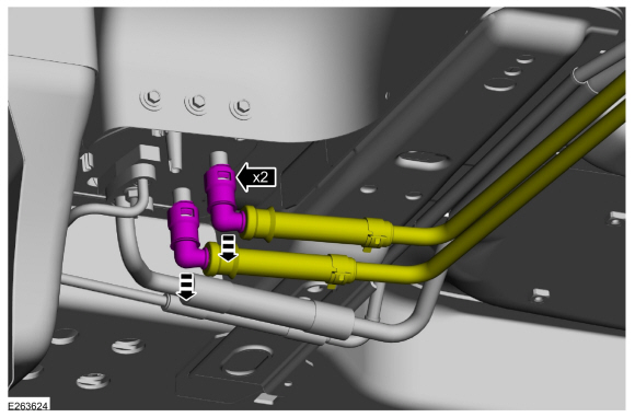
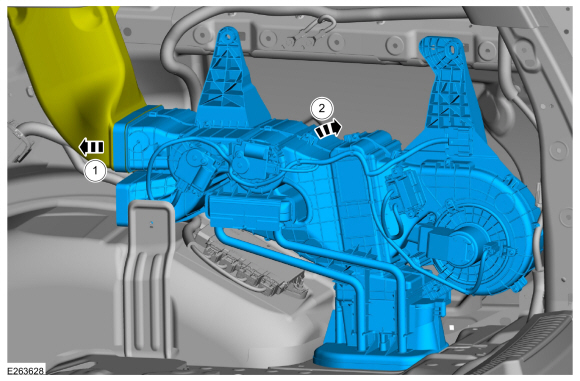
Disconnect the quick release couplings from the rear heater core.
Refer to: Quick Release Coupling (310-00 Fuel System - General Information - 3.5L EcoBoost (272kW/370PS)) .
 |
-
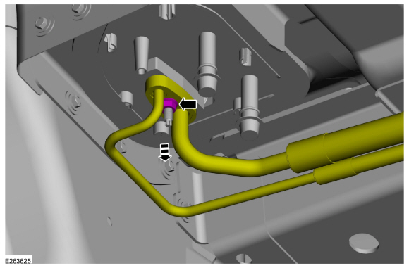
Remove the nut and position the rear thermostatic expansion valve manifold and tube assembly aside.
-
Make sure to cover any open ports to prevent debris from entering the system.
Torque: 80 lb.in (9 Nm)
-
Make sure to cover any open ports to prevent debris from entering the system.
 |
-
-
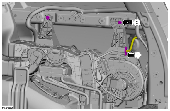
Disconnect the electrical connector.
-
Remove the bolts.
Torque: 71 lb.in (8 Nm)
-
Disconnect the electrical connector.
 |
-
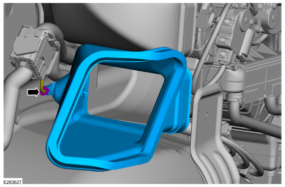
Disconnect the electrical connector and remove the rear footwell duct.
 |
-
-
Disconnect the duct.
-
Remove the rear climate control housing.
-
Disconnect the duct.
 |
Installation
-
To install, reverse the removal procedure.
-
NOTICE: Only use the specified material to lubricate the seals.
Install and lubricate new O-ring seals. Refer to the appropriate Specifications in Group 412.
-
Lubricate the refrigerant system with the correct amount
of clean PAG oil. Refer to the appropriate Refrigerant Oil Adding
procedure in Group 412.
-
Fill and bleed the cooling system.
Refer to: Cooling System Draining, Vacuum Filling and Bleeding (303-03 Engine Cooling - 3.5L EcoBoost (272kW/370PS)) .
 Rear Blower Motor Speed Control. Removal and Installation
Removal
NOTE:
Removal steps in this procedure may contain installation details.
Remove the RH loadspace trim panel.
Refer to: Loadspace Trim Panel (501-05 Interior Trim and Ornamentation, Removal and Installation)...
 Rear Evaporator. Removal and Installation
Removal
NOTICE:
During the removal or installation of components, cap, tape
or otherwise appropriately protect all openings and tubes/fittings to
prevent the ingress of dirt or other contamination...
Other information:
Lincoln Navigator 2018-2026 Workshop Manual: Vehicle Dynamics Control Module (VDM). Removal and Installation
Removal NOTICE: Electronic modules are sensitive to static electrical charges. If exposed to these charges, damage may result. NOTE: Removal steps in this procedure may contain installation details. NOTE: The current PMI process must begin with the current VDM installed...
Lincoln Navigator 2018-2026 Workshop Manual: Center Registers. Removal and Installation
Special Tool(s) / General Equipment Interior Trim Remover Removal NOTE: Removal steps in this procedure may contain installation details. Release the clips and remove the FDIM bracket cover. Use the General Equipment: Interior Trim Remover Remove the bolt and disconnect the LVDS connector...
Categories
- Manuals Home
- 4th Gen Lincoln Navigator Service Manual (2018 - 2026)
- SYNC Module [APIM]. Removal and Installation
- Power Running Board (PRB). Diagnosis and Testing
- Telematics Control Unit (TCU) Module. Removal and Installation
- Brake Service Mode Activation and Deactivation. General Procedures
- Rear Bumper. Removal and Installation
Rear Camber Adjustment. General Procedures
Special Tool(s) / General Equipment
Wheel Alignment SystemActivation
NOTICE: Suspension fasteners are critical parts that affect the performance of vital components and systems. Failure of these fasteners may result in major service expense. Use the same or equivalent parts if replacement is necessary. Do not use a replacement part of lesser quality or substitute design. Tighten fasteners as specified.
Using alignment equipment and the manufacturer's instructions, measure the rear camber.Use the General Equipment: Wheel Alignment System