Lincoln Navigator: Automatic Transmission - 10-Speed Automatic Transmission – 10R80 / Planetary Assembly. Description and Operation
Planetary Gearset Exploded View
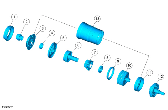
| Item | Description |
| 1 | Ring gear No. 1 |
| 2 | Sun gear No. 1 |
| 3 | Planetary carrier No. 1 |
| 4 | Sun gear No. 2 |
| 5 | Planetary carrier No. 2 |
| 6 | Ring gear No. 2 |
| 7 | Planetary carrier No. 3 |
| 8 | Sun gear No. 3 |
| 9 | Ring gear No. 3 |
| 10 | Shell and sun gear No. 4 |
| 11 | Ring gear No. 4 |
| 12 | Output shaft and planetary carrier No. 4 assembly |
| 13 | Cylinder (clutch and planetary container) |
The 10-speed transmission has 4 planetary gearsets. Each gearset consists of a ring gear, a sun gear and a carrier. The gear sets are numbered 1 through 4, from the front to the back of the transmission. There are several direct connections between the gearsets:
- Sun gears No. 1 and 2 are directly connected together with gear splines.
- Planetary carrier No. 1 and ring gear No. 4 are directly connected together with the cylinder (clutch and planetary container).
- Ring gear No. 2 and sun gear No. 3 are directly connected together with a shaft.
- Ring gear No. 3 and shell and sun gear No. 4 are directly connected together through the shell of the shell and sun gear No. 4.

 Transmission Fluid Auxiliary Pump. Description and Operation
Item
Description
1
Transmission fluid auxiliary pump
2
Transmission fluid auxiliary pump tube
3
Transmission fluid auxiliary pump tube seal
4
Transmission fluid auxiliary pump tube O-ring
5
Transmission fluid auxiliary pump fluid inl..
Other information:
Lincoln Navigator 2018-2026 Workshop Manual: Liftgate Trim Panel. Removal and Installation
Removal Release the clips and remove the liftgate upper middle trim panel. NOTE: LH shown, RH similar. On both sides. Release the clips and remove the liftgate side trim panel. Release the tabs and remove the liftgate handle bolt cover. ..
Lincoln Navigator 2018-2026 Workshop Manual: Rear Bumper Cover. Removal and Installation
Special Tool(s) / General Equipment Interior Trim Remover Removal NOTE: Removal steps in this procedure may contain installation details. With the vehicle in NEUTRAL, position it on a hoist. Refer to: Jacking and Lifting (100-02 Jacking and Lifting, Description and Operation). On both sides. Remove the push pins and the screw. To..
Categories
- Manuals Home
- 4th Gen Lincoln Navigator Service Manual (2018 - 2026)
- Front Seat. Removal and Installation
- Front Bumper Cover. Removal and Installation
- Telematics Control Unit (TCU) Module. Removal and Installation
- SYNC Module [APIM]. Removal and Installation
- Rear View Mirrors - System Operation and Component Description. Description and Operation
Differential Case Runout Check. General Procedures
Special Tool(s) / General Equipment
 205-1016
Installer, Differential Bearing
TKIT-2014D-ROW2
TKIT-2014D-FL_ROW
 205-153
(T80T-4000-W)
205-153
(T80T-4000-W)
Handle
 205-D061
(D83T-4205-C2)
205-D061
(D83T-4205-C2)
Step Plate Dial Indicator Three Leg Puller Punch