Lincoln Navigator: Automatic Transmission - 10-Speed Automatic Transmission – 10R80 / Output Shaft Seal. Removal and Installation
Special Tool(s) / General Equipment
 |
100-001
(T50T-100-A)
Slide Hammer |
 |
307-309 Remover, Torque Converter Seal TKIT-1994-FMH/FLMH TKIT-1994-LMH/MH TKIT-1994-FH |
 |
307-660 Installer, Front Pump Seal TKIT-2009C-F TKIT-2009C-ROW |
 |
307-776 Socket, Outputshaft Locknut |
Materials
| Name | Specification |
|---|---|
| Motorcraft® High Temperature 4x4 Front Axle and Wheel Bearing Grease XG-11 |
WSS-M1C267-A1 |
Removal
-
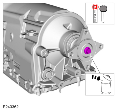
With the vehicle in NEUTRAL, position it on a hoist.
Refer to: Jacking and Lifting (100-02 Jacking and Lifting, Description and Operation).
Rear Wheel Drive (RWD) vehicles
-
Remove the rear driveshaft assembly.
Refer to: Rear Driveshaft (205-01 Driveshaft, Removal and Installation).
-
Remove and discard the output shaft flange bolt (7N134).
 |
-
Slide the output shaft flange back to index mark the output shaft to the flange.
 |
-
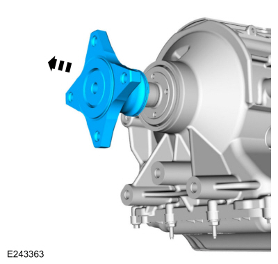
Remove the output shaft flange.
 |
-
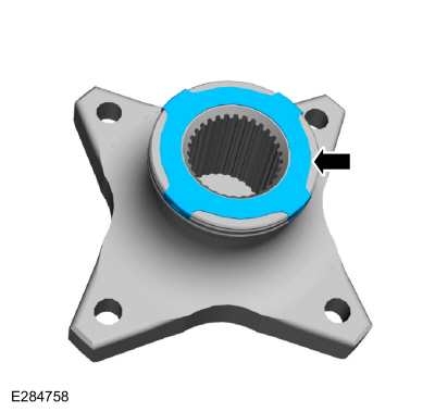
Remove the anti-ting ring.
 |
-
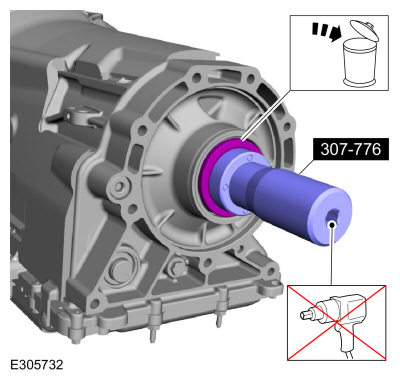
Using the special tool, remove and discard the output shaft nut (7085).
Use Special Service Tool: 307-776 Socket, Outputshaft Locknut.
 |
Four-Wheel Drive (4WD) vehicles
-
Remove the transfer case assembly.
All vehicles
-
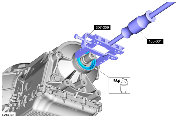
Using the special tools, remove and discard the output shaft seal (7052).
Use Special Service Tool: 307-309 Remover, Torque Converter Seal. , 100-001 (T50T-100-A) Slide Hammer.
 |
Installation
-
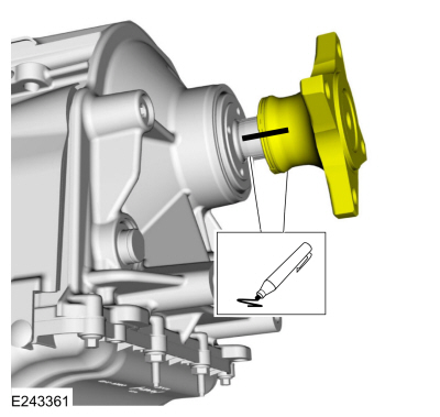
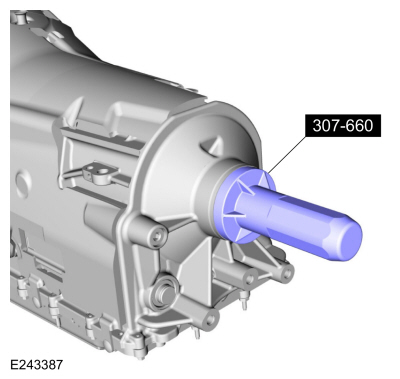
Using the special tool, install the new output shaft seal.
Use Special Service Tool: 307-660 Installer, Front Pump Seal.
 |
Rear Wheel Drive (RWD) vehicles
-
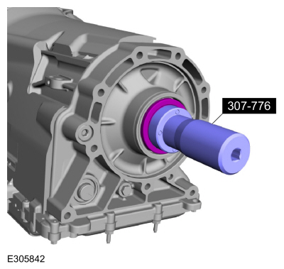
Using the special tool, install the new output shaft nut.
Use Special Service Tool: 307-776 Socket, Outputshaft Locknut.
Torque: 148 lb.ft (200 Nm)
 |
-
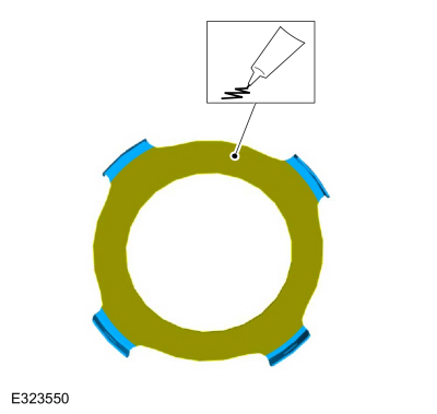
Apply a light coating of the lubrication to the back side of the anti-ting ring.
Material: Motorcraft® High Temperature 4x4 Front Axle and Wheel Bearing Grease / XG-11 (WSS-M1C267-A1)
 |
-
Install the anti-ting ring.
|
-
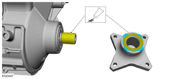
Apply a light coating of the lubrication to the output shaft splines and the anti-ting ring.
Material: Motorcraft® High Temperature 4x4 Front Axle and Wheel Bearing Grease / XG-11 (WSS-M1C267-A1)
 |
-
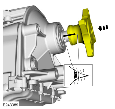
Align the index marks on the output shaft and the output shaft flange made during removal.
 |
-
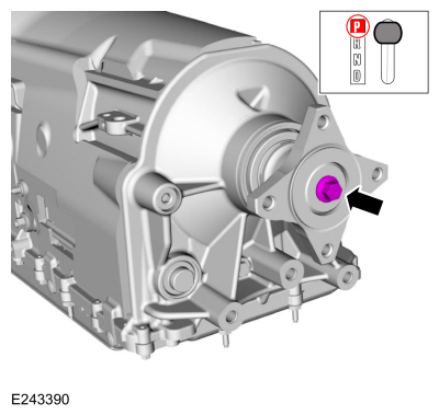
Install the new output shaft flange bolt.
Torque: 81 lb.ft (110 Nm)
 |
-
Install the rear driveshaft assembly.
Refer to: Rear Driveshaft (205-01 Driveshaft, Removal and Installation).
Four-Wheel Drive (4WD) vehicles
-
Install the transfer case assembly.
All vehicles
-
Check the transmission fluid level.
Refer to: Transmission Fluid Level Check (307-01 Automatic Transmission - 10-Speed Automatic Transmission – 10R80, General Procedures).
 Intermediate Speed Sensor B (ISSB). Removal and Installation
Removal
Remove the main control valve body.
Refer to: Main Control Valve Body (307-01 Automatic Transmission -
10-Speed Automatic Transmission – 10R80, Removal and Installation)...
 Output Shaft Speed (OSS) Sensor. Removal and Installation
Removal
Remove the main control valve body.
Refer to: Main Control Valve Body (307-01 Automatic Transmission -
10-Speed Automatic Transmission – 10R80, Removal and Installation)...
Other information:
Lincoln Navigator 2018-2026 Workshop Manual: Direct Current/Direct Current (DC/DC) Converter Control Module - Overview. Description and Operation
OVERVIEW The Low voltage Direct Current/Direct Current (DC/DC) converter, also known as the Voltage Quality Module (VQM), is on vehicles equipped with the auto-start-stop system. Auto-start-stop technology provides fuel savings by turning the engine off when the vehicle is stopped and then automatically restarting the engine when the driver is ready to continue driving...
Lincoln Navigator 2018-2026 Workshop Manual: Third Row Seat Head Restraint. Removal and Installation
Removal NOTE: Double seat shown, single seat similar. Remove the third row seat. Refer to: Third Row Seat (501-10C Third Row Seats, Removal and Installation). Remove the child safety seat tether anchor bezels...
Categories
- Manuals Home
- 4th Gen Lincoln Navigator Service Manual (2018 - 2026)
- Transmission Fluid Level Check. General Procedures
- Identification Codes. Description and Operation
- All Terrain Control Module (ATCM). Removal and Installation
- Remote Function Actuator (RFA) Module. Removal and Installation
- Rear Bumper. Removal and Installation
Wheel to Hub Runout Minimization. General Procedures
Check
NOTE: Wheel-to-hub optimization is important. Clearance between the wheel and hub can be used to offset or neutralize the Road Force® or run-out of the wheel and tire assembly. For every 0.001 inch of wheel-to-hub clearance, the Road Force® can be affected between 1 and 3 pounds depending on the tire stiffness.
NOTE: The example below illustrates how the clearance between the wheel and the hub can be used to offset the high spot of radial run-out or Road Force®. Following the procedure will make sure of the best optimization.
Position the wheel and tire assembly on the vehicle so that the high spot location of radial run-out or Road Force® is at the 6 o'clock position and