Lincoln Navigator: Supplemental Restraint System / Clockspring. Removal and Installation
Removal
 WARNING:
The following procedure prescribes critical repair steps
required for correct restraint system operation during a crash. Follow
all notes and steps carefully. Failure to follow step instructions may
result in incorrect operation of the restraint system and increases the
risk of serious personal injury or death in a crash.
WARNING:
The following procedure prescribes critical repair steps
required for correct restraint system operation during a crash. Follow
all notes and steps carefully. Failure to follow step instructions may
result in incorrect operation of the restraint system and increases the
risk of serious personal injury or death in a crash.
NOTE: Removal steps in this procedure may contain installation details.
-
Refer to: Pyrotechnic Device Health and Safety Precautions (100-00 General Information, Description and Operation).
WARNING:
Before beginning any service procedure in this
manual, refer to health and safety warnings in section 100-00 General
Information. Failure to follow this instruction may result in serious
personal injury.
-
Remove the following items:
-
NOTE: Follow the unique instructions or graphic for this step in installation.
Remove the steering wheel.
Refer to: Steering Wheel (211-04 Steering Column, Removal and Installation).
-
Remove the steering column shrouds.
Refer to: Steering Column Shrouds (501-05 Interior Trim and Ornamentation, Removal and Installation).
-
-
-
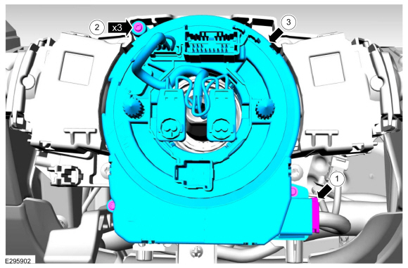
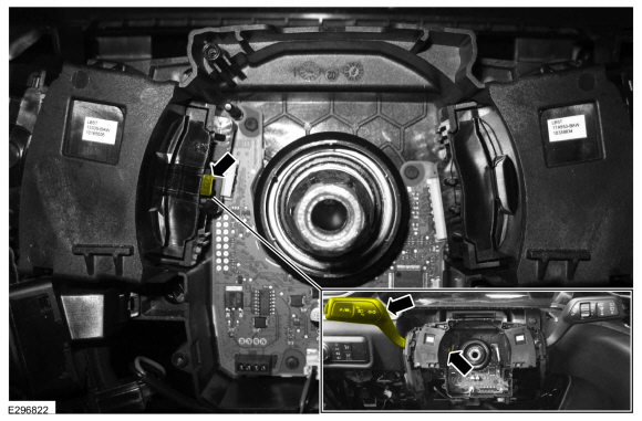
Disconnect the clockspring electrical connector.
-
Remove the clockspring screws.
-
NOTE: Follow the unique instructions or graphic for this step in installation.
Remove the clockspring.
-
Disconnect the clockspring electrical connector.
 |
Installation
NOTICE: If installing a new clockspring, do not remove the clockspring anti-rotation key until the steering wheel is installed. If the anti-rotation key has been removed before installing the steering wheel, the clockspring must be centered. Failure to follow this instruction may result in component damage and/or system failure.
-
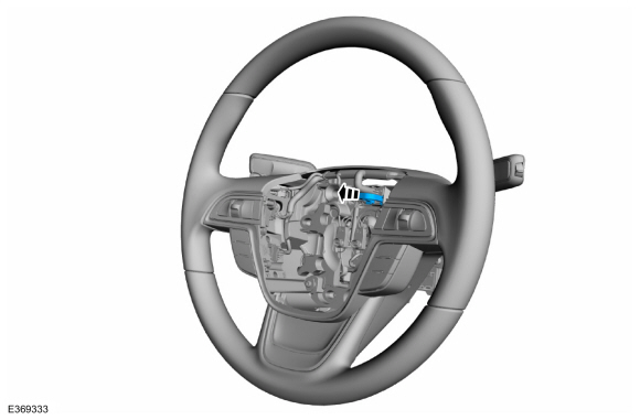
NOTE: Illustration shows the cancel tab in the off position.
Before installing the clockspring, position the turn signal stalk to the off position.
-
Ensure the turn signal cancel tab is in the off position.
-
Ensure the turn signal cancel tab is in the off position.
 |
-
To install, reverse the removal procedure.
-
NOTE: This step is only necessary if adjustment is required.
Adjust the clockspring.
Refer to: Clockspring Adjustment (501-20B Supplemental Restraint System, General Procedures).
-
Install the steering wheel.
-
Remove the anti-rotation key from a new clockspring after installing the steering wheel.
Refer to: Steering Wheel (211-04 Steering Column, Removal and Installation).
-
Remove the anti-rotation key from a new clockspring after installing the steering wheel.
 |
 C-Pillar Side Impact Sensor. Removal and Installation
Special Tool(s) /
General Equipment
Interior Trim Remover
Removal
WARNING:
The following procedure prescribes critical repair steps
required for correct restraint system operation during a crash...
 Driver Airbag. Removal and Installation
Removal
WARNING:
The following procedure prescribes critical repair steps
required for correct restraint system operation during a crash...
Other information:
Lincoln Navigator 2018-2026 Workshop Manual: Jacking and Lifting. Description and Operation
Stay in Neutral Mode NOTE: Always put your vehicle in Stay in Neutral mode when entering an automatic car wash. Failure to do this could result in vehicle damage not covered by warranty. Stay in Neutral mode allows your vehicle to stay in Neutral when you exit your vehicle...
Lincoln Navigator 2018-2026 Workshop Manual: Rear Door Window Glass. Removal and Installation
Special Tool(s) / General Equipment Interior Trim Remover Removal NOTE: LH side shown, RH side similar. Remove the fore rear door upper moulding. Refer to: Rear Door Upper Moulding (501-08 Exterior Trim and Ornamentation, Removal and Installation)...
Categories
- Manuals Home
- 4th Gen Lincoln Navigator Service Manual (2018 - 2026)
- All Terrain Control Module (ATCM). Removal and Installation
- Power Running Board (PRB). Diagnosis and Testing
- Rear Bumper. Removal and Installation
- Transmission Fluid Drain and Refill. General Procedures
- Head Up Display (HUD) Module Calibration. General Procedures
Rear Drive Axle and Differential. Diagnosis and Testing
Symptom Chart(s)
Diagnostics in this manual assume a certain skill level and knowledge of Ford-specific diagnostic practices.
REFER to: Diagnostic Methods (100-00 General Information, Description and Operation).
Symptom Chart - Differential
Symptom Chart - Differential
Condition Actions Axle overheating GO to Pinpoint Test A Broken gear teeth on the ring gear or pinion GO to Pi