Lincoln Navigator: Supplemental Restraint System / C-Pillar Side Impact Sensor. Removal and Installation
Special Tool(s) / General Equipment
| Interior Trim Remover |
Removal
 WARNING:
The following procedure prescribes critical repair steps
required for correct restraint system operation during a crash. Follow
all notes and steps carefully. Failure to follow step instructions may
result in incorrect operation of the restraint system and increases the
risk of serious personal injury or death in a crash.
WARNING:
The following procedure prescribes critical repair steps
required for correct restraint system operation during a crash. Follow
all notes and steps carefully. Failure to follow step instructions may
result in incorrect operation of the restraint system and increases the
risk of serious personal injury or death in a crash.
NOTE: LH shown, RH similar.
NOTE: Removal steps in this procedure may contain installation details.
-
Refer to: Pyrotechnic Device Health and Safety Precautions (100-00 General Information, Description and Operation).
WARNING:
Before beginning any service procedure in this
manual, refer to health and safety warnings in section 100-00 General
Information. Failure to follow this instruction may result in serious
personal injury.
-
Depower the SRS .
Refer to: Supplemental Restraint System (SRS) Depowering (501-20B Supplemental Restraint System, General Procedures).
-
Remove the C-pillar trim panel.
Refer to: C-Pillar Trim Panel (501-05 Interior Trim and Ornamentation, Removal and Installation).
-
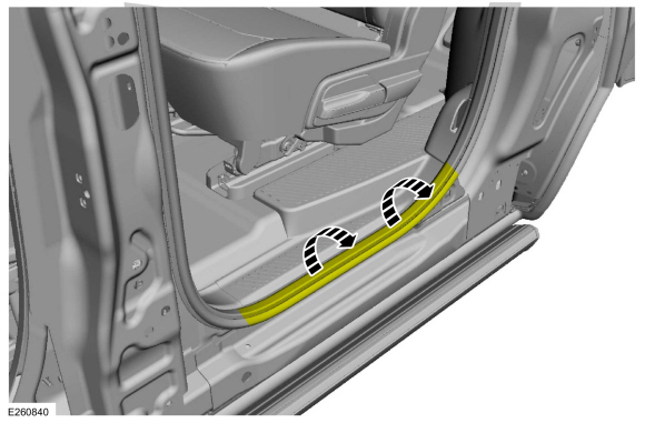
Position the rear door weather-strip aside.
 |
-
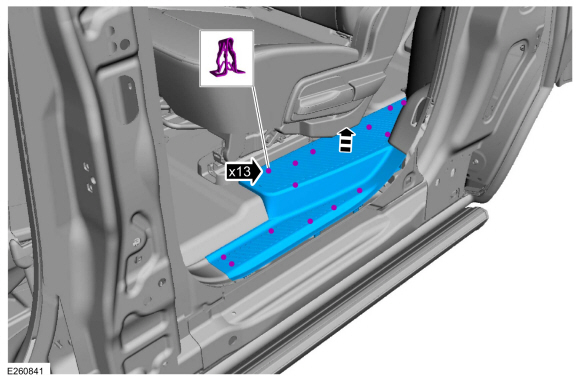
NOTE: Long wheelbase shown, short wheelbase similar.
Release the clips and remove the rear door scuff plate trim panel.
 |
-
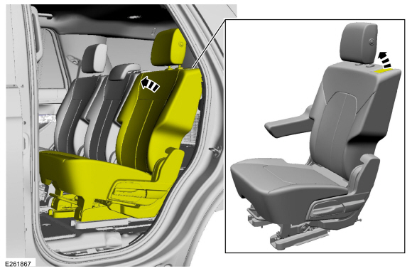
Position the second row seat forward.
 |
-
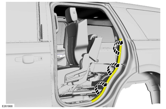
Position the weather-strip away from the C-pillar trim panel.
 |
-
Remove the loadspace trim panel screw cover and the screws.
Use the General Equipment: Interior Trim Remover
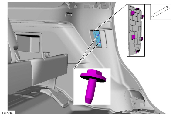 |
-
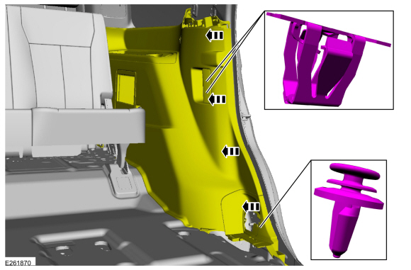
NOTE: Second row seat removed for clarity.
NOTE: Short wheelbase shown, long wheelbase similar.
Release the clips and position the loadspace trim panel away enough to access the side impact sensor.
 |
-
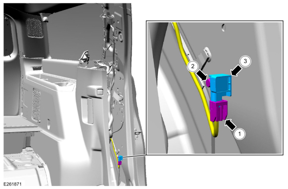
For short wheelbase vehicles.
-
Disconnect the electrical connector.
-
Remove the bolt.
Torque: 93 lb.in (10.5 Nm)
-
Remove the C-pillar side impact sensor.
-
Disconnect the electrical connector.
 |
-
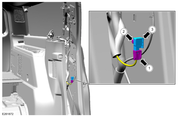
For long wheelbase vehicles.
-
Disconnect the electrical connector.
-
Remove the bolt.
Torque: 93 lb.in (10.5 Nm)
-
Remove the C-pillar side impact sensor.
-
Disconnect the electrical connector.
 |
Installation
-
NOTE: The C-pillar side impact sensor mating surfaces must be smooth and allow for a flush attachment to each other.
To install, reverse the removal procedure.
-
Repower the SRS .
Refer to: Supplemental Restraint System (SRS) Repowering (501-20B Supplemental Restraint System, General Procedures).
 Supplemental Restraint System (SRS) Repowering. General Procedures
Repower
WARNING:
Incorrect repair techniques or actions can cause an
accidental Supplemental Restraint System (SRS) deployment. Never
compromise or depart from these instructions...
 Clockspring. Removal and Installation
Removal
WARNING:
The following procedure prescribes critical repair steps
required for correct restraint system operation during a crash...
Other information:
Lincoln Navigator 2018-2026 Workshop Manual: Shift Solenoids (SS). Removal and Installation
Materials Name Specification Motorcraft® MERCON® ULV Automatic Transmission FluidXT-12-QULV WSS-M2C949-A, MERCON® ULV Removal NOTE: If a new SS is installed, carry out the adaptive learning drive cycle procedure at the end of the repair...
Lincoln Navigator 2018-2026 Workshop Manual: Coolant Pump. Removal and Installation
Special Tool(s) / General Equipment Hose Clamp Remover/Installer Materials Name Specification Motorcraft® Yellow Concentrated Antifreeze/CoolantVC-13-G WSS-M97B57-A1 Motorcraft® Orange Concentrated Antifreeze/CoolantVC-3-B WSS-M97B44-D Removal Drain the cooling system...
Categories
- Manuals Home
- 4th Gen Lincoln Navigator Service Manual (2018 - 2026)
- Rear Bumper. Removal and Installation
- Neutral Flat Tow Activation and Deactivation. General Procedures
- Identification Codes. Description and Operation
- Transmission Fluid Level Check. General Procedures
- Windshield Washer Pump. Removal and Installation
Front Stabilizer Bar Link. Removal and Installation
Removal
NOTICE: Suspension fasteners are critical parts that affect the performance of vital components and systems. Failure of these fasteners may result in major service expense. Use the same or equivalent parts if replacement is necessary. Do not use a replacement part of lesser quality or substitute design. Tighten fasteners as specified.
NOTE: Removal steps in this procedure may contain installation details.
With the vehicle in NEUTRAL, position it on a hoist.Refer to: Jacking and Lifting (100-02 Jacking and Lifting, Description and Operation).
NOTICE: Do not use power tools to remove or install the stabilizer bar