Lincoln Navigator: Front End Sheet Metal Repairs / Cowl Panel. Removal and Installation
Special Tool(s) /
General Equipment
| 6.5 mm Drill Bit |
| Polydrive Bit Socket |
| Rivet Gun |
| Self-Piercing Rivet (SPR) Remover/Installer |
| Belt Sander |
| Hot Air Gun |
| Locking Pliers |
Materials
| Name |
Specification |
Metal Bonding Adhesive
TA-1, TA-1-B, 3M™ 08115, LORD Fusor® 108B, Henkel Teroson EP 5055 |
-
|
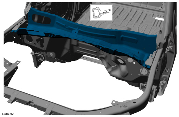
Removal
NOTE:
The cowl panel is available as a top panel, inner panel and
side panels. The following assumes full component replacement of the top
and inner panels. Adjust to meet repair needs.
NOTE:
Aluminum body panels are highly receptive to heat transfer.
With the extensive use of structural adhesives and non-structural
sealers used in vehicle construction, the potential of heat transfer
could impact adhesives and sealers in non-associated panels during the
repair process. Many repairs areas that utilize structural adhesive may
be separated after fastener removal by using a panel chisel along the
joint/flange. Using heat not exceeding 425° F to loosen a bonded panel
should only be done when all panels in the joint will be replaced and new adhesive applied.
NOTE:
Flow drill screw (FDS) fasteners are not to be reused. Remove and discard.
NOTE:
Adequately protect all adjacent areas against cutting and grinding procedures.
-
Depower the SRS .
Refer to: Supplemental Restraint System (SRS) Depowering (501-20B Supplemental Restraint System, General Procedures).
-
On Both Sides:
Remove the fender.
Refer to: Fender (501-02 Front End Body Panels, Removal and Installation).
-
Remove the hood, cowl panel grille and cowl panel.
Refer to: Hood (501-02 Front End Body Panels, Removal and Installation).
Refer to: Cowl Panel Grille (501-02 Front End Body Panels, Removal and Installation).
Refer to: Cowl Panel (501-02 Front End Body Panels, Removal and Installation).
-
Remove the windshield wiper motor and associated linkage.
Refer to: Rear Window Wiper Pivot Arm (501-16 Wipers and Washers, Removal and Installation).
Refer to: Wiper Linkage Assembly (501-16 Wipers and Washers, Removal and Installation).
Refer to: Windshield Wiper Motor (501-16 Wipers and Washers, Removal and Installation).
-
Remove the windshield glass.
Refer to: Fixed Glass (501-11 Glass, Frames and Mechanisms, General Procedures).
-
If Required:
Dimensionally restore the vehicle to pre-damage condition.
Refer to: Body and Frame (501-26 Body Repairs - Vehicle Specific Information and Tolerance Checks, Description and Operation).
-
Remove the instrument panel and console.
Refer to: Floor Console (501-12 Instrument Panel and Console, Removal and Installation).
Refer to: Instrument Panel Upper Section (501-12 Instrument Panel and Console, Removal and Installation).
Refer to: Instrument Panel (501-12 Instrument Panel and Console, Removal and Installation).
-
Position the carpet, electrical modules and wiring harnesses away from the working area.
-
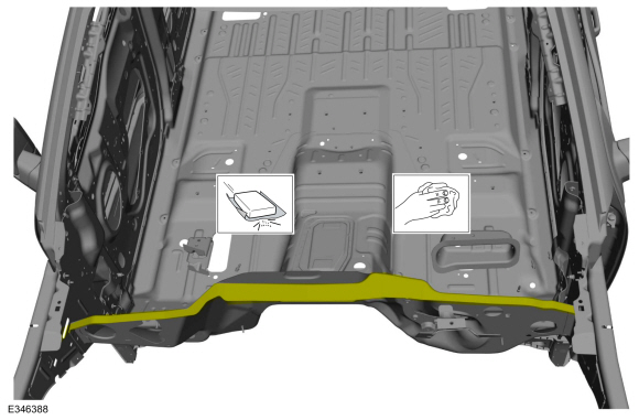
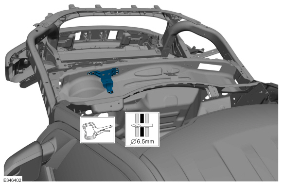
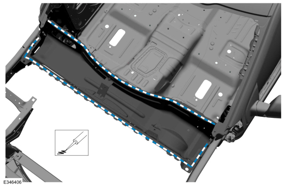
NOTE:
Pay particular attention to the location of adhesives or sealers to aid in installation.
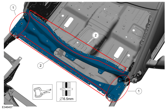
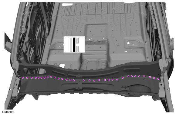
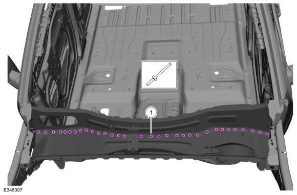
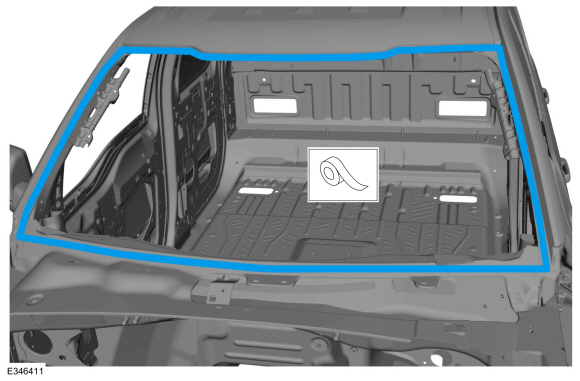
Remove the fasteners and the cowl top.
Use the General Equipment: Self-Piercing Rivet (SPR) Remover/Installer
Use the General Equipment: Belt Sander
Use the General Equipment: Polydrive Bit Socket
Use the General Equipment: Hot Air Gun
-
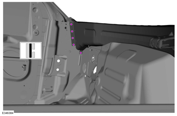
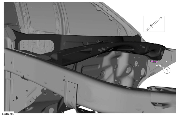
On Both Sides:
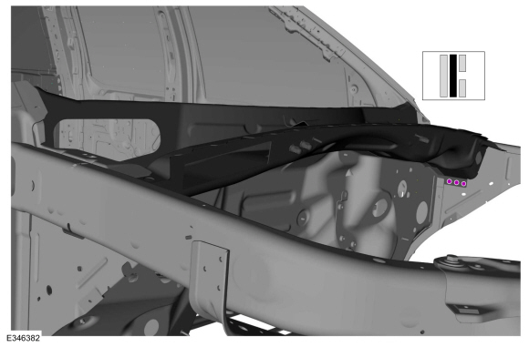
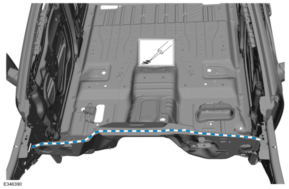
Remove the fasteners.
Use the General Equipment: Self-Piercing Rivet (SPR) Remover/Installer
Use the General Equipment: Belt Sander
Use the General Equipment: Polydrive Bit Socket
-
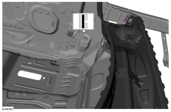
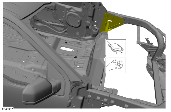
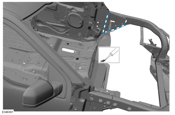
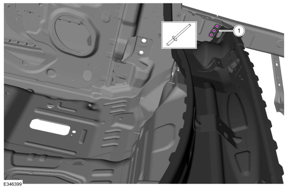
On Both Sides:
Remove the fasteners.
Use the General Equipment: Self-Piercing Rivet (SPR) Remover/Installer
Use the General Equipment: Belt Sander
Use the General Equipment: Polydrive Bit Socket
-
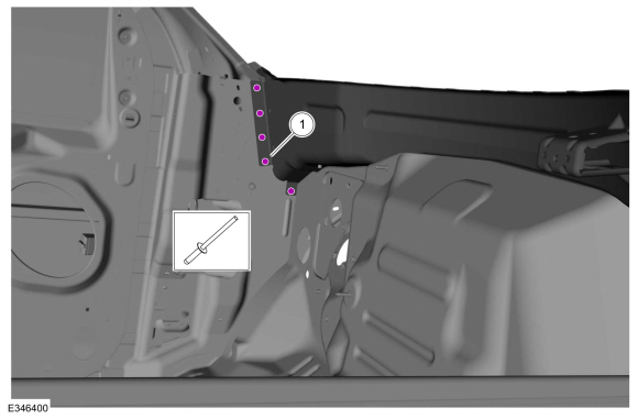
Remove the fasteners.
Use the General Equipment: Self-Piercing Rivet (SPR) Remover/Installer
Use the General Equipment: Belt Sander
Use the General Equipment: Polydrive Bit Socket
-
Remove the fasteners.
Use the General Equipment: Self-Piercing Rivet (SPR) Remover/Installer
Use the General Equipment: Belt Sander
Use the General Equipment: Polydrive Bit Socket
-
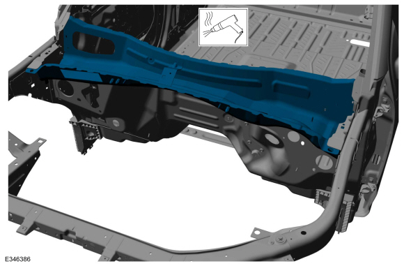
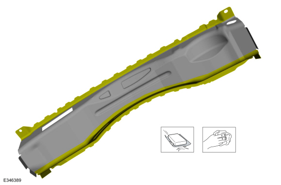
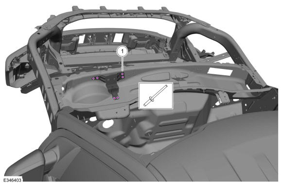
NOTE:
Pay particular attention to the location of adhesives or sealers to aid in installation.
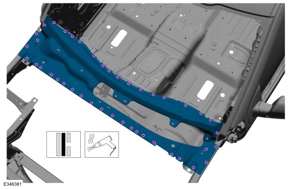
Remove the inner cowl panel.
Use the General Equipment: Hot Air Gun
Installation
NOTE:
The cowl panel is available as a top panel, inner panel and
side panels. The following assumes full component replacement of the top
and inner panels. Adjust to meet repair needs.
NOTE:
Self-Piercing Rivet (SPR) fasteners may not be placed
directly over original self-piercing rivet (SPR) fastener location. They
must be placed adjacent to original location matching original
quantity.
NOTE:
Blind or solid rivets may be used in place of self-piercing
rivet (SPR) fasteners in the original self-piercing rivet (SPR)
fasteners location after enlarging hole to 6.5 mm.
NOTE:
Adequately protect all adjacent areas against cutting and grinding procedures.
-
On Both Sides: Using 80-120 grit sand paper, sand to remove old adhesive and clean.
-
Using 80-120 grit sand paper, sand to remove old adhesive and clean.
-
Using 80-120 grit sand paper, sand to remove e-coat and clean.
-
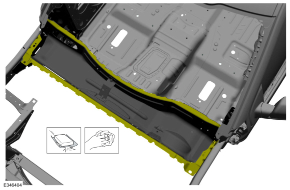
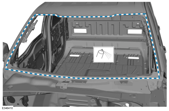
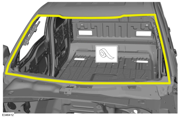
Apply adhesive.
Material: Metal Bonding Adhesive
/ TA-1, TA-1-B, 3M™ 08115, LORD Fusor® 108B, Henkel Teroson EP 5055
-
On Both Sides:
Apply adhesive.
Material: Metal Bonding Adhesive
/ TA-1, TA-1-B, 3M™ 08115, LORD Fusor® 108B, Henkel Teroson EP 5055
-
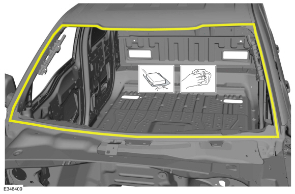
Install, properly position and clamp the inner cowl panel.
Use the General Equipment: Locking Pliers
-
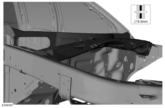
On Both Sides:
Drill for blind rivet fasteners.
Use the General Equipment: 6.5 mm Drill Bit
-
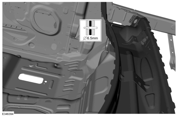
On Both Sides:
Drill for blind rivet fasteners.
Use the General Equipment: 6.5 mm Drill Bit
-
On Both Sides:
Drill for blind rivet fasteners.
Use the General Equipment: 6.5 mm Drill Bit
-
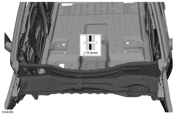
Drill for blind rivet fasteners.
Use the General Equipment: 6.5 mm Drill Bit
-
Install the fasteners.
|
Item
|
SPR Number
|
SPR Code
|
Henrob®, Car-O-Liner®, CMO®, Chief®, Spanesi®, Wielander and Schill® Mandrel
|
Pro-Spot® Mandrel
|
Blind Rivet
|
Solid Rivet
|
Rivnut®
|
|
1
|
-
|
-
|
-
|
-
|
W702512-S900C
|
-
|
-
|
Use the General Equipment: Rivet Gun
-
On Both Sides:
Install the fasteners.
|
Item
|
SPR Number
|
SPR Code
|
Henrob®, Car-O-Liner®, CMO®, Chief®, Spanesi®, Wielander and Schill® Mandrel
|
Pro-Spot® Mandrel
|
Blind Rivet
|
Solid Rivet
|
Rivnut®
|
|
1
|
-
|
-
|
-
|
-
|
W708777-S900C
|
-
|
-
|
Use the General Equipment: Rivet Gun
-
On Both Sides:
Install the fasteners.
|
Item
|
SPR Number
|
SPR Code
|
Henrob®, Car-O-Liner®, CMO®, Chief®, Spanesi®, Wielander and Schill® Mandrel
|
Pro-Spot® Mandrel
|
Blind Rivet
|
Solid Rivet
|
Rivnut®
|
|
1
|
-
|
-
|
-
|
-
|
W708777-S900C
|
-
|
-
|
Use the General Equipment: Rivet Gun
-
On Both Sides:
Install the fasteners.
|
Item
|
SPR Number
|
SPR Code
|
Henrob®, Car-O-Liner®, CMO®, Chief®, Spanesi®, Wielander and Schill® Mandrel
|
Pro-Spot® Mandrel
|
Blind Rivet
|
Solid Rivet
|
Rivnut®
|
|
1
|
-
|
-
|
-
|
-
|
W708777-S900C
|
-
|
-
|
Use the General Equipment: Rivet Gun
-
Install, properly position, clamp the reinforcement and drill for blind rivet fasteners.
Use the General Equipment: Locking Pliers
Use the General Equipment: 6.5 mm Drill Bit
-
Install the fasteners.
|
Item
|
SPR Number
|
SPR Code
|
Henrob®, Car-O-Liner®, CMO®, Chief®, Spanesi®, Wielander and Schill® Mandrel
|
Pro-Spot® Mandrel
|
Blind Rivet
|
Solid Rivet
|
Rivnut®
|
|
1
|
-
|
-
|
-
|
-
|
W702512-S900C
|
-
|
-
|
Use the General Equipment: Rivet Gun
-
Using 80-120 grit sand paper, sand to remove old adhesive or e-coat and clean.
-
Using 80-120 grit sand paper, sand to remove e-coat and clean.
-
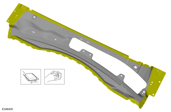
Apply adhesive.
Material: Metal Bonding Adhesive
/ TA-1, TA-1-B, 3M™ 08115, LORD Fusor® 108B, Henkel Teroson EP 5055
-
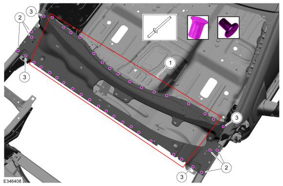
NOTE:
Item 2 should not be drilled if using self-piercing rivet (SPR) fasteners.
Install, properly position, clamp and drill the cowl top panel for fasteners installation.
Use the General Equipment: Locking Pliers
Use the General Equipment: 6.5 mm Drill Bit
 |
|
-
NOTE:
Self-piercing rivet (SPR) fasteners may not be
placed directly over original self-piercing rivet (SPR) location. They
must be placed adjacent to original location matching original quantity.
NOTE:
Blind rivet or solid rivet fasteners may be used in
place of self-piercing rivet (SPR) fasteners after enlarging holes to
6.5 mm.
NOTE:
Blind rivet or solid rivet fasteners may be used in
place of self-piercing rivet (SPR) fasteners after enlarging holes to
6.5 mm.
Install the fasteners.
|
Item
|
SPR Number
|
SPR Code
|
Henrob®, Car-O-Liner®, CMO®, Chief®, Spanesi®, Wielander and Schill® Mandrel
|
Pro-Spot® Mandrel
|
Blind Rivet
|
Solid Rivet
|
Rivnut®
|
|
1
|
W708713-S900
|
AS
|
DZ09-025/H
|
SA-0400/SA-0401
|
W702512-S900C
|
W790376-S900
|
-
|
|
2
|
-
|
-
|
-
|
-
|
W702512-S900C
|
-
|
-
|
|
3
|
-
|
-
|
-
|
-
|
W708777-S900C
|
-
|
-
|
Use the General Equipment: Self-Piercing Rivet (SPR) Remover/Installer
Use the General Equipment: Rivet Gun
-
Sand to remove old adhesive, paint, e-coat and clean.
-
Apply a Ford approved epoxy-based primer and allow to dry.
-
Mask the windshield channel.
-
Refinish the entire repair using a Ford approved paint system.
-
Unmask the windshield channel.
-
Install a new VIN plate.
Refer to: Identification Codes (100-01 Identification Codes, Description and Operation).
-
Install the windshield glass.
Refer to: Fixed Glass (501-11 Glass, Frames and Mechanisms, General Procedures).
-
Restore corrosion protection.
Refer to: Corrosion Prevention (501-25 Body Repairs - General Information, General Procedures).
-
Reposition all electrical modules, wiring harnesses and the carpet to original location.
-
Install the instrument panel and console.
Refer to: Instrument Panel (501-12 Instrument Panel and Console, Removal and Installation).
Refer to: Instrument Panel Upper Section (501-12 Instrument Panel and Console, Removal and Installation).
Refer to: Floor Console (501-12 Instrument Panel and Console, Removal and Installation).
-
Install the windshield wiper motor and associated linkage.
Refer to: Rear Window Wiper Motor (501-16 Wipers and Washers, Removal and Installation).
Refer to: Wiper Linkage Assembly (501-16 Wipers and Washers, Removal and Installation).
Refer to: Windshield Wiper Pivot Arm (501-16 Wipers and Washers, Removal and Installation).
-
On Both Sides:
Install the fender.
Refer to: Fender (501-02 Front End Body Panels, Removal and Installation).
-
Install the cowl panel, cowl panel grille and hood.
Refer to: Cowl Panel (501-02 Front End Body Panels, Removal and Installation).
Refer to: Cowl Panel Grille (501-02 Front End Body Panels, Removal and Installation).
Refer to: Hood (501-02 Front End Body Panels, Removal and Installation).
-
Align the hood.
Refer to: Hood Alignment (501-03 Body Closures, General Procedures).
-
Repower the SRS .
Refer to: Supplemental Restraint System (SRS) Repowering (501-20B Supplemental Restraint System, General Procedures).
Special Tool(s) /
General Equipment
6.5 mm Drill Bit
11 mm Drill Bit
Rivet Gun
Self-Piercing Rivet (SPR) Remover/Installer
Belt Sander
Hot Air Gun
8 mm Drill Bit
Locking Pliers
Materials
Name
Specification
Metal Bonding AdhesiveTA-1, TA-1-B, 3M™ 08115, LORD Fusor® 108B, Henkel Teroson EP 5055
-
..
Other information:
Removal
NOTE:
This step is only necessary when installing a new component.
NOTE:
The PMI (programmable module installation) process must begin with the
current SCMJ installed. If the current SCMJ does not respond to the
diagnostic scan tool, the tool may prompt for As-Built Data as part of
the repair.
Using a diagnostic scan tool, begin the PMI process for the SCM..
Removal
Remove the main control valve body.
Refer to: Main Control Valve Body (307-01 Automatic Transmission -
10-Speed Automatic Transmission – 10R80, Removal and Installation).
Remove the intermediate speed sensor B.
Slide the plastic lock to the unlocked position.
While pressing the plastic tab, disconnect the electrical connector.
..


 Cowl Side Panel. Removal and Installation