Lincoln Navigator: Supplemental Restraint System / Occupant Classification System (OCS) Sensor. Removal and Installation
Special Tool(s) / General Equipment
| Flat Headed Screw Driver | |
| Interior Trim Remover |
Removal
 WARNING:
The following procedure prescribes critical repair steps
required for correct restraint system operation during a crash. Follow
all notes and steps carefully. Failure to follow step instructions may
result in incorrect operation of the restraint system and increases the
risk of serious personal injury or death in a crash.
WARNING:
The following procedure prescribes critical repair steps
required for correct restraint system operation during a crash. Follow
all notes and steps carefully. Failure to follow step instructions may
result in incorrect operation of the restraint system and increases the
risk of serious personal injury or death in a crash.
NOTICE: To prevent system failure, carry out the OCS reset when a front passenger seat cushion assembly is removed, a new seat cushion heater mat is installed or an OCS service kit is installed. Use a diagnostic scan tool to carry out the OCS reset command.
NOTE: The OCS components (seat cushion foam and trim cover, heater mat, plastic carrier, seat cushion adjustable bolsters (if equipped) and OCS bladder with OCSM ) are calibrated to each other and serviced as an assembly. The OCS service kit components are not to be installed separately. If a new OCS or OCS components are needed, a new OCS service kit must be installed. A new passenger seat cushion heater mat can be installed separately.
NOTE: Removal steps in this procedure may contain installation details.
All seats
-
Refer to: Pyrotechnic Device Health and Safety Precautions (100-00 General Information, Description and Operation).
WARNING:
Before beginning any service procedure in this
manual, refer to health and safety warnings in section 100-00 General
Information. Failure to follow this instruction may result in serious
personal injury.
-
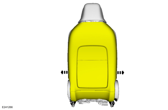
Raise the seat to its highest point of travel.
 |
-
If equipped with a power leg extension.
Raise and extend the leg extensions.
 |
-
NOTE: Follow the unique instructions or graphic for this step in the installation.
Remove the front passenger seat.
Refer to: Front Seat (501-10A Front Seats, Removal and Installation).
-
Release the front seat wiring harness and electrical
connector retainers and position the front seat wiring harnesses aside.
 |
-
Detach the back panel straps from the seat track and position the back panel aside.
 |
-
If equipped with multi-contour seat.
Release the coupling retainers and separate the cushion adjuster bolster hoses from the cushion SCMH .
 |
-
Detach the wiring harness retainers and disconnect the cushion heater mat electrical connector.
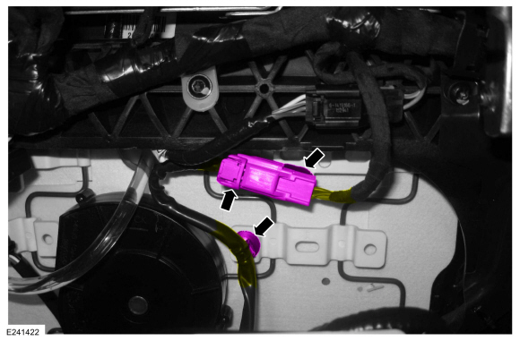 |
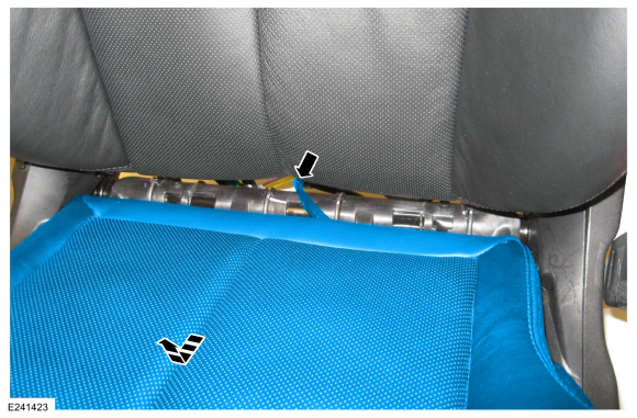
-
Disconnect the OCS sensor, remove the OCS sensor bracket screw and route out the sensor with the bracket.
Torque: 44 lb.in (5 Nm)
 |
-
Release the cushion cover J-clips from the leg extensions.
 |
Vehicles with multi-contour seats
-
If equipped.
Remove the video display.
Refer to: Information and Entertainment System - Component Location (415-00 Information and Entertainment System - General Information - Vehicles With: SYNC 4, Description and Operation).
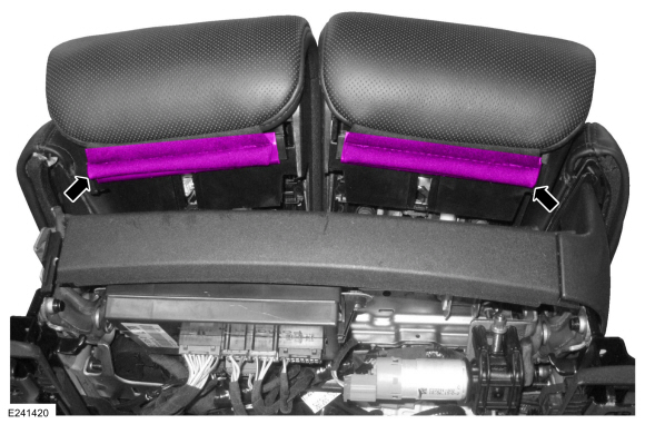
-
NOTICE: The back panel finish can be easily marred or torn, use care when working around it.
Raise and partially separate the head restraint rear cover enough to disengage the clips from the back panel.
Use the General Equipment: Interior Trim Remover
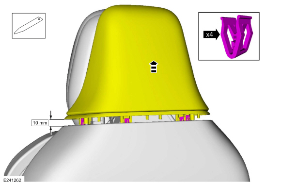 |
-
On both sides.
Grasp the back panel where it meets the module trim, pull to release the clips and separate the back panel from the module trim.
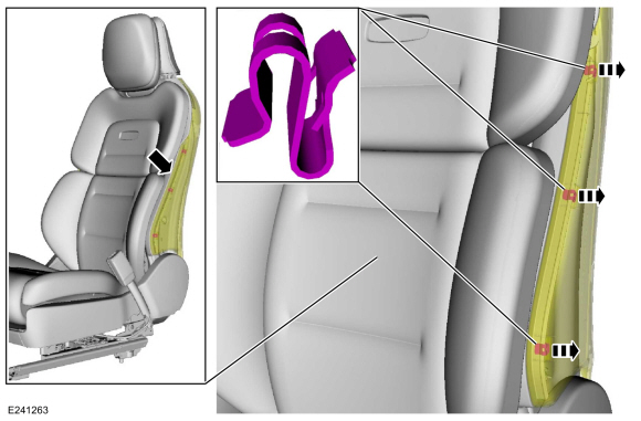 |
-
On both sides.
Using the interior trim remover, place it in between the plastic substrate and the clip, pry and detach the module clips from the back panel windows.
Use the General Equipment: Interior Trim Remover
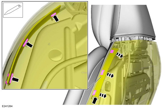 |
-
Pull out at the bottom, release the clips and detach the back panel from the backrest frame.
 |
-
Pull out at the sides of the back panel.
 |
-
Pull down and out and remove the back panel.
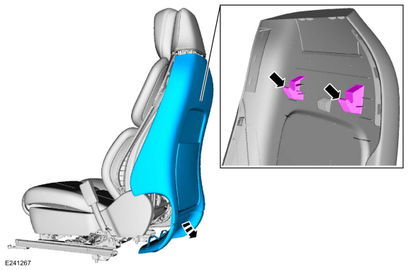 |
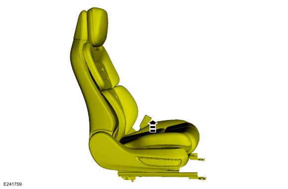
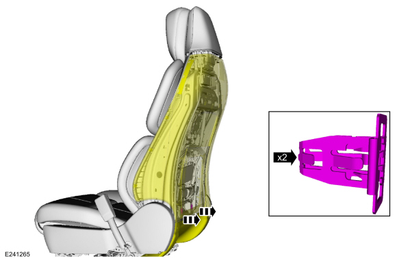
All seats
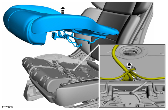
-
At the attachment points, slide the seat cushion and OCS assembly
rearward and upward, detaching the carrier from the cushion module.
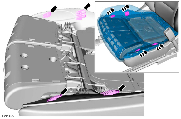 |
-
-
NOTE: Only the carrier portion of the seat cushion and OCS assembly is shown.
Push the rear of the seat cushion and OCS assembly up, disengaging the carrier from the locator pins.
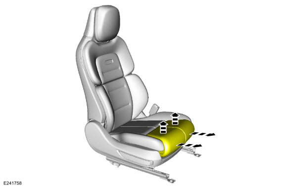
-
Pull the seat cushion and OCS assembly out from between the seat track and backrest.
-
 |
-
Route the cushion heater mat wiring harness pigtail
out from between the seat track and backrest and continue seat cushion
and OCS assembly removal.
 |
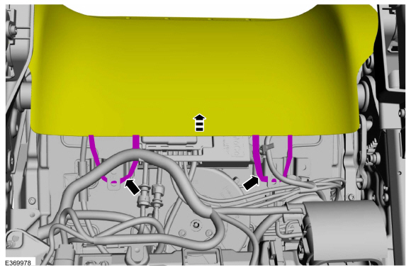
-
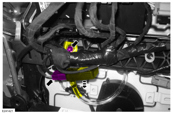
NOTICE: During installation, do not kink the OCS hose or the SRS will not operate correctly.
NOTICE: During installation, do not kink the multi-contour seat hose assembly or the multi-contour seat will not operate correctly.
NOTE: For proper installation, note the location of the OCS hose and multi-contour seat hose assembly (if equipped) as they pass through the seat.
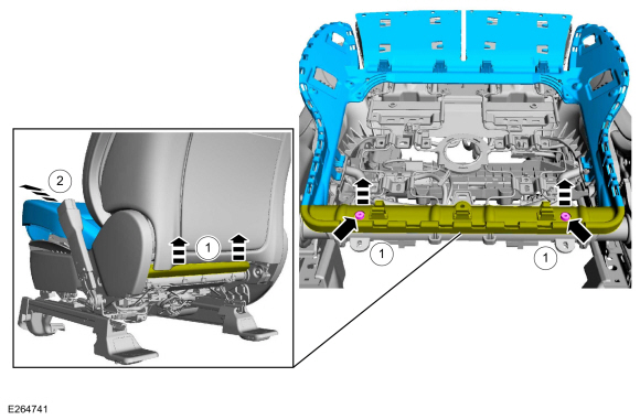
Remove the seat cushion and OCS assembly.
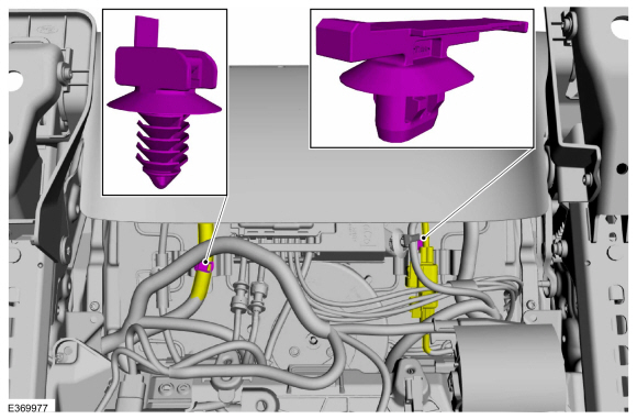
-
Route out the OCS hose with sensor and the multi-contour seat hose assembly (if equipped).
-
Route out the OCS hose with sensor and the multi-contour seat hose assembly (if equipped).
 |
-
NOTE: This step is only necessary if installing a new OCS .
NOTE: Follow the unique instructions or graphic for this step in the installation.
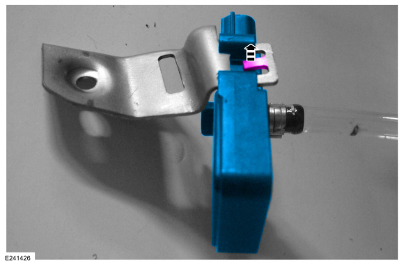
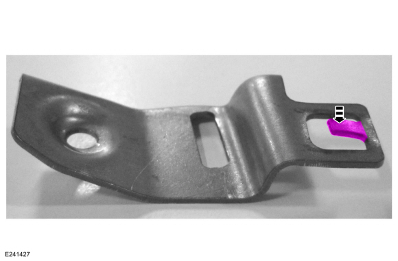
Bend the tab away from the OCS sensor and slide the sensor off the bracket.
 |
Installation
-
NOTICE: Inspect the OCS bladder, seat cushion pan and support assembly for any foreign objects before installing the OCS to the seat cushion pan. Remove any foreign objects. Failure to follow these instructions may result in incorrect operation of the OCS and may cause system failure.
NOTICE: Do not trap the pressure sensor hose incorrectly over the seat's suspension or spring. Route the hose so that it lays in a natural bend, and is not twisted due to being forced into an unnatural position. Failure to follow these instructions may result in component damage and/or system failure.
To install, reverse the removal procedure.
-
If required.
Install a new cushion heater mat.
Refer to: Seat Heater Mat Installation (501-10A Front Seats, General Procedures).
-
Bend the OCS sensor bracket tab back.
Use the General Equipment: Flat Headed Screw Driver
 |
-
Install the front passenger seat. Do not prove out the SRS at this time.
Refer to: Front Seat (501-10A Front Seats, Removal and Installation).
-
Sit in the driver seat in an upright position. Make sure
no objects are between you and any pyrotechnic device. Move the driver
seat to the rearmost position to maintain the maximum possible distance
from the driver airbag.
-
WARNING:
Occupant Classification System (OCS) parts are
calibrated as an assembly and must only be replaced in the configuration
they are sold. Never separate parts of an assembly. Failure to follow
this instruction may result in incorrect operation of the OCS and
increases the risk of serious personal injury or death in a crash.
WARNING:
Make sure the front passenger seat repair is
complete, the seat and all attached components (head restraint, seat
side shield, etc.) are correctly assembled, and the seat is correctly
installed to the vehicle before using System Reset to rezero the seat
weight. Failure to follow these instructions may result in incorrect
operation of the occupant classification system (OCS) and increases the
risk of serious personal injury or death in a crash.
NOTICE: To prevent system failure, take the following precautions before carrying out the OCS reset.
- Make sure the voltage to the OCSM is greater than 8 volts and less than 18 volts.
- Make sure the OCS is not below 42.8 °F ( 6 °C) or above 96.7 °F ( 36 °C) when initiating the OCS reset process. If the vehicle has been exposed to extreme cold or hot temperatures, the vehicle must be exposed and kept at a temperature between 42.8 °F ( 6 °C) to 96.7 °F ( 36 °C) for a minimum of 30 minutes.
- Make sure nothing is present on the passenger seat before and during the OCS reset process.
- Prior to carrying out the OCS reset, make sure a minimum of 8 seconds has elapsed after cycling the ignition switch on.
-
If the first system reset attempt was successful, proceed to prove out the SRS .
-
If the first system reset attempt was not successful, carry out a thorough visual inspection of the OCS
connector and wiring for damage, pressure sensor hose for kinks and or
damage, and seat-related wiring harness and body wiring harness
terminals and connectors for damage. Repair any concerns found and
proceed to the next step.
-
Carry out a second OCS reset. Cycle the ignition switch after the OCS
reset. If the second attempt is unsuccessful, install a new OCS service
kit.
-
Prove out the SRS
. Verify all airbags are installed and connected and the ignition is
OFF. Wait 10 seconds then turn the ignition ON and monitor the airbag
warning indicator. The airbag warning indicator illuminates continuously
for approximately 6 seconds and turns off. Continue to monitor the
airbag warning indicator for approximately 30 seconds, as this is the
time required for the RCM to complete testing of the SRS .
-
-
If a SRS
fault is present, the airbag warning indicator either fails to light,
remains lit continuously or flashes. The flashing may not occur until
approximately 30 seconds after the ignition has been turned from OFF to
ON. If this occurs, diagnose and repair any SRS faults before proceeding with other repairs.
-
If, after the ignition has been turned on for 30
seconds, the airbag warning indicator remains unlit with no chime or SRS
message displayed in the message center, no SRS fault is present.
-
If the airbag warning indicator is inoperative and a SRS
fault exists, a chime sounds in a pattern of 5 sets of 5 beeps or a
message displays in the message center. If this occurs, diagnose and
repair the airbag warning indicator and any SRS faults before proceeding with other repairs.
-
If a SRS
fault is present, the airbag warning indicator either fails to light,
remains lit continuously or flashes. The flashing may not occur until
approximately 30 seconds after the ignition has been turned from OFF to
ON. If this occurs, diagnose and repair any SRS faults before proceeding with other repairs.
-
Using a diagnostic scan tool, clear all Continuous Memory Diagnostic Trouble Codes (CMDTCs) from all modules.
 Front Impact Severity Sensor. Removal and Installation
Removal
WARNING:
The following procedure prescribes critical repair steps
required for correct restraint system operation during a crash...
 Passenger Airbag. Removal and Installation
Removal
WARNING:
The following procedure prescribes critical repair steps
required for correct supplemental restraint system operation during a
crash...
Other information:
Lincoln Navigator 2018-2026 Workshop Manual: Side Airbag. Removal and Installation
Special Tool(s) / General Equipment Interior Trim Remover Removal WARNING: The following procedure prescribes critical repair steps required for correct restraint system operation during a crash. Follow all notes and steps carefully...
Lincoln Navigator 2018-2026 Workshop Manual: Engine. Disassembly
Special Tool(s) / General Equipment 205-142 (T80T-4000-J) Installer, Differential Bearing Cone 205-150 (T80T-4000-S) Installer, Spindle Bearing 205-153 (T80T-4000-W) Handle 303-1246Engine Spreader BarTKIT-2006UF-FLMTKIT-2006UF-ROW 303-1247VCT Spark Plug Tube Seal Remover and InstallerTKIT-2006UF-FLMTKIT-2006UF-ROW 303-1..
Categories
- Manuals Home
- 4th Gen Lincoln Navigator Service Manual (2018 - 2026)
- All Terrain Control Module (ATCM). Removal and Installation
- Rear View Mirrors - System Operation and Component Description. Description and Operation
- Remote Function Actuator (RFA) Module. Removal and Installation
- Rear Bumper. Removal and Installation
- Power Running Board (PRB). Diagnosis and Testing
Differential Case Runout Check. General Procedures
Special Tool(s) / General Equipment
 205-1016
Installer, Differential Bearing
TKIT-2014D-ROW2
TKIT-2014D-FL_ROW
 205-153
(T80T-4000-W)
205-153
(T80T-4000-W)
Handle
 205-D061
(D83T-4205-C2)
205-D061
(D83T-4205-C2)
Step Plate Dial Indicator Three Leg Puller Punch