Lincoln Navigator: Electronic Engine Controls - 3.5L EcoBoost (272kW/370PS) / Intake Air Temperature (IAT) Sensor. Removal and Installation
Removal
NOTE: Removal steps in this procedure may contain installation details.
-
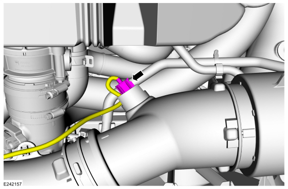
Disconnect the IAT sensor electrical connector.
 |
-
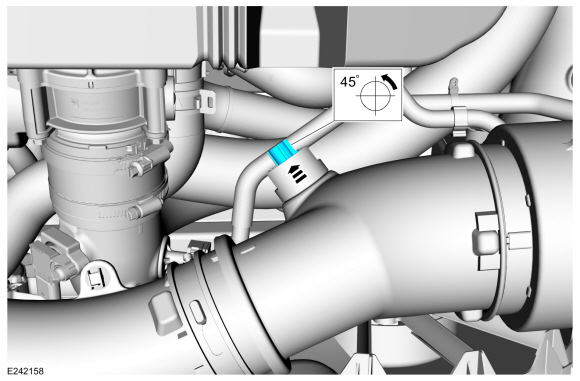
Remove the IAT sensor.
 |
Installation
-
To install, reverse the removal procedure.

 Knock Sensor (KS). Removal and Installation
Removal
NOTE:
Removal steps in this procedure may contain installation details.
Remove the direct injection fuel rail LH and RH side...
Other information:
Lincoln Navigator 2018-2026 Workshop Manual: Second Row Seat Manual Release Handle. Removal and Installation
Special Tool(s) / General Equipment Interior Trim Remover Removal NOTE: LH seat shown, others similiar. Remove the second row seat manual release handle bezel. Slide the release handle bezel rearward...
Lincoln Navigator 2018-2026 Workshop Manual: Transmission Case. Disassembly
Special Tool(s) / General Equipment 204-594Forcing screw 307-744Remover, Output Shaft Bearing Remove and discard the park pawl actuator rod sleeve roll pin (7G100), move the park pawl out of the park pawl actuator rod sleeve and remove the park pawl actuator rod sleeve...
Categories
- Manuals Home
- 4th Gen Lincoln Navigator Service Manual (2018 - 2026)
- Neutral Flat Tow Activation and Deactivation. General Procedures
- Power Running Board (PRB). Diagnosis and Testing
- Rear Bumper. Removal and Installation
- Telematics Control Unit (TCU) Module. Removal and Installation
- All Terrain Control Module (ATCM). Removal and Installation
Wheel to Hub Runout Minimization. General Procedures
Check
NOTE: Wheel-to-hub optimization is important. Clearance between the wheel and hub can be used to offset or neutralize the Road Force® or run-out of the wheel and tire assembly. For every 0.001 inch of wheel-to-hub clearance, the Road Force® can be affected between 1 and 3 pounds depending on the tire stiffness.
NOTE: The example below illustrates how the clearance between the wheel and the hub can be used to offset the high spot of radial run-out or Road Force®. Following the procedure will make sure of the best optimization.
Position the wheel and tire assembly on the vehicle so that the high spot location of radial run-out or Road Force® is at the 6 o'clock position and