Lincoln Navigator: Electronic Engine Controls - 3.5L EcoBoost (272kW/370PS) / Heated Oxygen Sensor (HO2S). Removal and Installation
Special Tool(s) / General Equipment
 |
303-476
(T94P-9472-A)
Socket, Exhaust Gas Oxygen Sensor TKIT-1994-LM/M TKIT-1994-F TKIT-1994-FLM/FM |
Materials
| Name | Specification |
|---|---|
| Motorcraft® High Temperature Nickel Anti-Seize Lubricant XL-2 |
- |
| Motorcraft® Penetrating and Lock Lubricant XL-1 |
- |
Removal
Right hand (RH) Heated oxygen sensor (HO2S)
-
With the vehicle in NEUTRAL, position it on a hoist.
Refer to: Jacking and Lifting (100-02 Jacking and Lifting, Description and Operation).
-
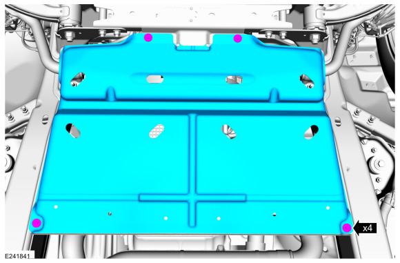
If equipped, remove the underbody shield.
 |
-
-
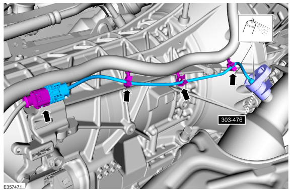
Disconnect the electrical connector and harness retainers.
-
Apply penetrating oil to sensor, using the special tool remove the HO2S .
Use Special Service Tool: 303-476 (T94P-9472-A) Socket, Exhaust Gas Oxygen Sensor.
Material: Motorcraft® Penetrating and Lock Lubricant / XL-1
-
Disconnect the electrical connector and harness retainers.
 |
Left hand (LH) Heated oxygen sensor (HO2S)
-
With the vehicle in NEUTRAL, position it on a hoist.
Refer to: Jacking and Lifting (100-02 Jacking and Lifting, Description and Operation).
-
If equipped, remove the underbody shield.
|
-
-
Disconnect the electrical connector and harness retainer.
-
Apply penetrating oil to sensor, using the special tool remove the HO2S .
Use Special Service Tool: 303-476 (T94P-9472-A) Socket, Exhaust Gas Oxygen Sensor.
Material: Motorcraft® Penetrating and Lock Lubricant / XL-1
-
Disconnect the electrical connector and harness retainer.
 |
Installation
Left hand (LH) Heated oxygen sensor (HO2S)
-
-
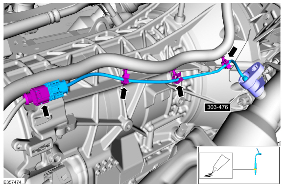
Apply anti-seize to thread of sensor, using special tool install the HO2S .
Torque: 35 lb.ft (48 Nm)
-
Connect the electrical connector and harness retainer.
Use Special Service Tool: 303-476 (T94P-9472-A) Socket, Exhaust Gas Oxygen Sensor.
Material: Motorcraft® High Temperature Nickel Anti-Seize Lubricant / XL-2
-
Apply anti-seize to thread of sensor, using special tool install the HO2S .
 |
-
If equipped, install the underbody shield.
Torque: 71 lb.in (8 Nm)
|
Right hand (RH) Heated oxygen sensor (HO2S)
-
-
Apply anti-seize to thread of sensor, using special tool install the HO2S .
Torque: 35 lb.ft (48 Nm)
-
Connect the electrical connector and harness retainers.
Use Special Service Tool: 303-476 (T94P-9472-A) Socket, Exhaust Gas Oxygen Sensor.
Material: Motorcraft® High Temperature Nickel Anti-Seize Lubricant / XL-2
-
Apply anti-seize to thread of sensor, using special tool install the HO2S .
 |
-
If equipped, install the underbody shield.
Torque: 71 lb.in (8 Nm)
|
 Fuel Rail Pressure and Temperature Sensor. Removal and Installation
Removal
Release the fuel system pressure.
Refer to: Fuel System Pressure Release (310-00 Fuel System - General
Information - 3.5L EcoBoost (272kW/370PS), General Procedures)...
 Intake Air Temperature (IAT) Sensor. Removal and Installation
Removal
NOTE:
Removal steps in this procedure may contain installation details.
Disconnect the IAT sensor electrical connector...
Other information:
Lincoln Navigator 2018-2026 Workshop Manual: Front Stabilizer Bar. Removal and Installation
Removal NOTICE: Suspension fasteners are critical parts that affect the performance of vital components and systems. Failure of these fasteners may result in major service expense. Use the same or equivalent parts if replacement is necessary...
Lincoln Navigator 2018-2026 Workshop Manual: Sealer, Underbody Protection Material and Adhesives. Description and Operation
Adhesives The correct adhesive bonding is essential to repairing the vehicle correctly. Adhesives and mechanical fasteners are used in all areas of the body structure in place of welding. In addition to providing a structural bond between components, adhesives can also help prevent wind noise, water leaks, exhaust fumes and dust from entering the vehicle...
Categories
- Manuals Home
- 4th Gen Lincoln Navigator Service Manual (2018 - 2026)
- Body Control Module (BCM). Removal and Installation
- Transmission Fluid Drain and Refill. General Procedures
- Brake Service Mode Activation and Deactivation. General Procedures
- Front Bumper Cover. Removal and Installation
- Windshield Washer Pump. Removal and Installation
Rear Drive Axle and Differential. Diagnosis and Testing
Symptom Chart(s)
Diagnostics in this manual assume a certain skill level and knowledge of Ford-specific diagnostic practices.
REFER to: Diagnostic Methods (100-00 General Information, Description and Operation).
Symptom Chart - Differential
Symptom Chart - Differential
Condition Actions Axle overheating GO to Pinpoint Test A Broken gear teeth on the ring gear or pinion GO to Pi