Lincoln Navigator: Information and Entertainment System - General Information - Vehicles With: SYNC 4 / Information and Entertainment System. Diagnosis and Testing
Diagnostic Trouble Code (DTC) Chart
Diagnostics in this manual assume a certain skill level and knowledge of Ford-specific diagnostic practices.
REFER to: Diagnostic Methods (100-00 General Information, Description and Operation).
| Module | DTC | Description | Action |
|---|---|---|---|
| ACM | B116A:01 | Handset Microphone: General Electrical Failure | GO to Pinpoint Test V |
| ACM | B116A:12 | Handset Microphone: Circuit Short To Battery | GO to Pinpoint Test V |
| ACM | B116A:14 | Handset Microphone: Circuit Short To Ground Or Open | GO to Pinpoint Test V |
| ACM | B117A:01 | Backup Microphone: General Electrical Failure | GO to Pinpoint Test V |
| ACM | B117A:12 | Backup Microphone: Circuit Short To Battery | GO to Pinpoint Test V |
| ACM | B117A:14 | Backup Microphone: Circuit Short To Ground Or Open | GO to Pinpoint Test V |
| ACM | B13F5:01 | Microphone 3: General Electrical Failure | GO to Pinpoint Test V |
| ACM | B13F5:12 | Microphone 3: Circuit Short To Battery | GO to Pinpoint Test V |
| ACM | B13F5:14 | Microphone 3: Circuit Short To Ground Or Open | GO to Pinpoint Test V |
| ACM | B150C:01 | Automobile Audio Bus (A2B) Node 1: General Electrical Failure | GO to Pinpoint Test C |
| ACM | B150C:11 | Automobile Audio Bus (A2B) Node 1: Circuit Short To Ground | GO to Pinpoint Test C |
| ACM | B150C:12 | Automobile Audio Bus (A2B) Node 1: Circuit Short To Battery | GO to Pinpoint Test C |
| ACM | B150C:13 | Automobile Audio Bus (A2B) Node 1: Circuit Open | GO to Pinpoint Test C |
| ACM | B150C:55 | Automobile Audio Bus (A2B) Node 1: Not Configured | GO to Pinpoint Test C |
| ACM | B150C:87 | Automobile Audio Bus (A2B) Node 1: Missing Message | GO to Pinpoint Test C |
| ACM | B150C:8F | Automobile Audio Bus (A2B) Node 1: Erratic | GO to Pinpoint Test C |
| ACM | B150C:95 | Automobile Audio Bus (A2B) Node 1: Incorrect Assembly | GO to Pinpoint Test C |
| ACM | B1511:01 | Automobile Audio Bus (A2B) Master Node: General Electrical Failure | GO to Pinpoint Test C |
| ACM | B1511:11 | Automobile Audio Bus (A2B) Master Node: Circuit Short To Ground | GO to Pinpoint Test C |
| ACM | B1511:12 | Automobile Audio Bus (A2B) Master Node: Circuit Short To Battery | GO to Pinpoint Test C |
| ACM | B1511:13 | Automobile Audio Bus (A2B) Master Node: Circuit Open | GO to Pinpoint Test C |
| ACM | B1511:95 | Automobile Audio Bus (A2B) Master Node: Incorrect Assembly | GO to Pinpoint Test C |
| ACM | B1A56:11 | Antenna: Circuit Short To Ground | GO to Pinpoint Test A |
| ACM | B1A56:15 | Antenna: Circuit Short To Battery Or Open | GO to Pinpoint Test A |
| ACM | B1A89:11 | Satellite Antenna: Circuit Short To Ground | GO to Pinpoint Test B |
| ACM | B1A89:13 | Satellite Antenna: Circuit Open | GO to Pinpoint Test B |
| ACM | U0100:00 | Lost Communication With ECM/PCM 'A': No Sub Type Information | GO to Pinpoint Test Y |
| ACM | U0121:00 | Lost Communication With Anti-Lock Brake System (ABS) Control Module 'A': No Sub Type Information | GO to Pinpoint Test Z |
| ACM | U0140:00 | Lost Communication With Body Control Module: No Sub Type Information | GO to Pinpoint Test AA |
| ACM | U0155:00 | Lost Communication With Instrument Panel Cluster (IPC) Control Module: No Sub Type Information | GO to Pinpoint Test AD |
| ACM | U0198:00 | Lost Communication With Telematic Control Module 'A': No Sub Type Information | GO to Pinpoint Test AF |
| ACM | U0238:00 | Lost Communication With Digital Audio Control Module 'D': No Sub Type Information | GO to Pinpoint Test AI |
| ACM | U0249:00 | Lost Communication With Entertainment Control Module -Rear 'B': No Sub Type Information | GO to Pinpoint Test AJ |
| ACM | U0253:00 | Lost Communication With Accessory Protocol Interface Module: No Sub Type Information | GO to Pinpoint Test AK |
| ACM | U0256:00 | Lost Communication With Front Controls Interface Module 'A': No Sub Type Information | GO to Pinpoint Test AL |
| ACM | U201A:51 | Control Module Main Calibration Data: Not Programmed | GO to Pinpoint Test AQ |
| ACM | U201B:04 | Control Module Calibration Data #2: System Internal Failures | GO to Pinpoint Test AQ |
| ACM | U201B:51 | Control Module Calibration Data #2: Not Programmed | GO to Pinpoint Test AQ |
| ACM | U201B:55 | Control Module Calibration Data #2: Not Configured | GO to Pinpoint Test AQ |
| ACM | U2024:00 | Control Module Cal-Config Data: No Sub Type Information | GO to Pinpoint Test AQ |
| ACM | U2024:57 | Control Module Cal-Config Data: Invalid/Incompatible Software Component | GO to Pinpoint Test AQ |
| ACM | U2026:54 | Control Module Cal-Config Data #3: Missing Calibration | GO to Pinpoint Test AQ |
| ACM | U2100:00 | Initial Configuration Not Complete: No Sub Type Information | GO to Pinpoint Test AQ |
| ACM | U2101:00 | Control Module Configuration Incompatible: No Sub Type Information | GO to Pinpoint Test AQ |
| ACM | U3000:41 | Control Module: General Checksum Failure | GO to Pinpoint Test AR |
| ACM | U3000:42 | Control Module: General Memory Failure | GO to Pinpoint Test AR |
| ACM | U3000:92 | Control Module: Performance Or Incorrect Operation | GO to Pinpoint Test AR |
| ACM | U3000:94 | Control Module: Unexpected Operation | GO to Pinpoint Test AR |
| ACM | U3000:96 | Control Module: Component Internal Failure | GO to Pinpoint Test AR |
| ACM | U3003:16 | Battery Voltage: Circuit Voltage Below Threshold | GO to Pinpoint Test AM |
| ACM | U3003:17 | Battery Voltage: Circuit Voltage Above Threshold | GO to Pinpoint Test AN |
| APIM | B108E:01 | Display: General Electrical Failure | GO to Pinpoint Test J |
| APIM | B108E:02 | Display: General Signal Failure | GO to Pinpoint Test J |
| APIM | B108E:4A | Display: Incorrect Component Installed | GO to Pinpoint Test J |
| APIM | B108E:4B | Display: Over Temperature | GO to Pinpoint Test J |
| APIM | B108E:87 | Display: Missing Message | GO to Pinpoint Test J |
| APIM | B119F:01 | GPS Antenna: General Electrical Failure | GO to Pinpoint Test S |
| APIM | B119F:13 | GPS Antenna: Circuit Open | GO to Pinpoint Test S |
| APIM | B1252:11 | USB Port: Circuit Short To Ground | GO to Pinpoint Test N |
| APIM | B1252:13 | USB Port: Circuit Open | GO to Pinpoint Test N |
| APIM | B14FD:11 | External Media Control Connectivity: Circuit Short To Ground | GO to Pinpoint Test N |
| APIM | B156D:54 | TCU Customer Connectivity Settings Synchronization With HMI: Missing Calibration | GO to Pinpoint Test AX |
| APIM | B156D:89 | TCU Customer Connectivity Settings Synchronization With HMI: Data Transfer Failure | GO to Pinpoint Test AX |
| APIM | B15EB:57 | Consumer Apps: Invalid/Incompatible Software Component | GO to Pinpoint Test AX |
| APIM | B1D79:11 | Microphone Input: Circuit Short To Ground | GO to Pinpoint Test L |
| APIM | B1D79:12 | Microphone Input: Circuit Short To Battery | GO to Pinpoint Test L |
| APIM | B1D79:13 | Microphone Input: Circuit Open | GO to Pinpoint Test L |
| APIM | U0100:00 | Lost Communication With ECM/PCM 'A': No Sub Type Information | GO to Pinpoint Test AV |
| APIM | U0121:00 | Lost Communication With Anti-Lock Brake System (ABS) Control Module 'A': No Sub Type Information | GO to Pinpoint Test AV |
| APIM | U0121:55 | Lost Communication With Anti-Lock Brake System (ABS) Control Module 'A': Not Configured | GO to Pinpoint Test AX |
| APIM | U0122:00 | Lost Communication With Vehicle Dynamics Control Module: No Sub Type Information | GO to Pinpoint Test AV |
| APIM | U0140:00 | Lost Communication With Body Control Module: No Sub Type Information | GO to Pinpoint Test AV |
| APIM | U0151:00 | Lost Communication With Restraints Control Module: No Sub Type Information | GO to Pinpoint Test AV |
| APIM | U0155:00 | Lost Communication With Instrument Panel Cluster (IPC) Control Module: No Sub Type Information | GO to Pinpoint Test AV |
| APIM | U0159:00 | Lost Communication With Parking Assist Control Module 'A': No Sub Type Information | GO to Pinpoint Test AV |
| APIM | U0162:00 | Lost Communication With Navigation Display Module: No Sub Type Information | GO to Pinpoint Test J |
| APIM | U0162:94 | Lost Communication With Navigation Display Module: Unexpected Operation | GO to Pinpoint Test J |
| APIM | U0184:00 | Lost Communication With Radio: No Sub Type Information | GO to Pinpoint Test AV |
| APIM | U0196:00 | Lost Communication With Entertainment Control Module-Rear 'A': No Sub Type Information | GO to Pinpoint Test AV |
| APIM | U0198:00 | Lost Communication With Telematic Control Module 'A': No Sub Type Information | GO to Pinpoint Test AV |
| APIM | U0208:00 | Lost Communication With 'Seat Control Module A': No Sub Type Information | GO to Pinpoint Test AV |
| APIM | U0209:00 | Lost Communication With 'Seat Control Module B': No Sub Type Information | GO to Pinpoint Test AV |
| APIM | U020C:00 | Lost Communication with Wireless Accessory Charging Module 'A': No Sub Type Information | GO to Pinpoint Test AV |
| APIM | U0212:00 | Lost Communication With Steering Column Control Module: No Sub Type Information | GO to Pinpoint Test AV |
| APIM | U0214:00 | Lost Communication With Remote Function Actuation Module: No Sub Type Information | GO to Pinpoint Test AV |
| APIM | U0232:00 | Lost Communication With Side Obstacle Detection Control Module 'A': No Sub Type Information | GO to Pinpoint Test AV |
| APIM | U0233:00 | Lost Communication With Side Obstacle Detection Control Module 'B': No Sub Type Information | GO to Pinpoint Test AV |
| APIM | U0238:00 | Lost Communication With Digital Audio Control Module 'D': No Sub Type Information | GO to Pinpoint Test AV |
| APIM | U023B:00 | Lost Communication With Image Processing Module B: No Sub Type Information | GO to Pinpoint Test AV |
| APIM | U024B:00 | Lost Communication with Seat Control Module 'G': No Sub Type Information | GO to Pinpoint Test AV |
| APIM | U024C:00 | Lost Communication with Seat Control Module 'H': No Sub Type Information | GO to Pinpoint Test AV |
| APIM | U0256:00 | Lost Communication With Front Controls Interface Module 'A': No Sub Type Information | GO to Pinpoint Test AV |
| APIM | U0415:00 | Invalid Data Received from Anti-Lock Brake System (ABS) Control Module 'A': No Sub Type Information | GO to Pinpoint Test AW |
| APIM | U0415:94 | Invalid Data Received from Anti-Lock Brake System (ABS) Control Module 'A': Unexpected Operation | GO to Pinpoint Test AW |
| APIM | U0416:00 | Invalid Data Received From Vehicle Dynamics Control Module: No Sub Type Information | GO to Pinpoint Test AW |
| APIM | U0422:00 | Invalid Data Received From Body Control Module: No Sub Type Information | GO to Pinpoint Test AW |
| APIM | U0452:00 | Invalid Data Received From Restraints Control Module: No Sub Type Information | GO to Pinpoint Test AW |
| APIM | U1A00:87 | Private Communication Network: Missing Message | GO to Pinpoint Test B |
| APIM | U1A00:94 | Private Communication Network: Unexpected Operation | GO to Pinpoint Test B |
| APIM | U2017:45 | Control Module Software #2: Program Memory Failure | GO to Pinpoint Test AX |
| APIM | U2017:51 | Control Module Software #2: Not Programmed | GO to Pinpoint Test AX |
| APIM | U2017:52 | Control Module Software #2: Not Activated | GO to Pinpoint Test AX |
| APIM | U2017:54 | Control Module Software #2: Missing Calibration | GO to Pinpoint Test AX |
| APIM | U2100:00 | Initial Configuration Not Complete: No Sub Type Information | GO to Pinpoint Test AX |
| APIM | U2101:00 | Control Module Configuration Incompatible: No Sub Type Information | GO to Pinpoint Test AX |
| APIM | U3000:04 | Control Module: System Internal Failures | GO to Pinpoint Test AY |
| APIM | U3000:05 | Control Module: System Programming Failures | GO to Pinpoint Test AY |
| APIM | U3000:09 | Control Module: Component Failures | GO to Pinpoint Test AY |
| APIM | U3000:41 | Control Module: General Checksum Failure | GO to Pinpoint Test AY |
| APIM | U3000:43 | Control Module: Special Memory Failure | GO to Pinpoint Test AY |
| APIM | U3000:57 | Control Module: Invalid/Incompatible Software Component | GO to Pinpoint Test AX |
| APIM | U3000:88 | Control Module: Bus Off | GO to Pinpoint Test AV |
| APIM | U3003:16 | Battery Voltage: Circuit Voltage Below Threshold | GO to Pinpoint Test AM |
| APIM | U3003:17 | Battery Voltage: Circuit Voltage Above Threshold | GO to Pinpoint Test AN |
| DSP | B128A:01 | Speaker #13: General Electrical Failure | GO to Pinpoint Test G |
| DSP | B128A:11 | Speaker #13: Circuit Short To Ground | GO to Pinpoint Test G |
| DSP | B128A:12 | Speaker #13: Circuit Short To Battery | GO to Pinpoint Test G |
| DSP | B128A:13 | Speaker #13: Circuit Open | GO to Pinpoint Test G |
| DSP | B128B:01 | Speaker #14: General Electrical Failure | GO to Pinpoint Test G |
| DSP | B128B:11 | Speaker #14: Circuit Short To Ground | GO to Pinpoint Test G |
| DSP | B128B:12 | Speaker #14: Circuit Short To Battery | GO to Pinpoint Test G |
| DSP | B128B:13 | Speaker #14: Circuit Open | GO to Pinpoint Test G |
| DSP | B128C:01 | Speaker #15: General Electrical Failure | GO to Pinpoint Test G |
| DSP | B128C:11 | Speaker #15: Circuit Short To Ground | GO to Pinpoint Test G |
| DSP | B128C:12 | Speaker #15: Circuit Short To Battery | GO to Pinpoint Test G |
| DSP | B128C:13 | Speaker #15: Circuit Open | GO to Pinpoint Test G |
| DSP | B128D:01 | Speaker #16: General Electrical Failure | GO to Pinpoint Test G |
| DSP | B128D:11 | Speaker #16: Circuit Short To Ground | GO to Pinpoint Test G |
| DSP | B128D:12 | Speaker #16: Circuit Short To Battery | GO to Pinpoint Test G |
| DSP | B128D:13 | Speaker #16: Circuit Open | GO to Pinpoint Test G |
| DSP | B128E:01 | Speaker #17: General Electrical Failure | GO to Pinpoint Test G |
| DSP | B128E:11 | Speaker #17: Circuit Short To Ground | GO to Pinpoint Test G |
| DSP | B128E:12 | Speaker #17: Circuit Short To Battery | GO to Pinpoint Test G |
| DSP | B128E:13 | Speaker #17: Circuit Open | GO to Pinpoint Test G |
| DSP | B128F:01 | Speaker #18: General Electrical Failure | GO to Pinpoint Test G |
| DSP | B128F:11 | Speaker #18: Circuit Short To Ground | GO to Pinpoint Test G |
| DSP | B128F:12 | Speaker #18: Circuit Short To Battery | GO to Pinpoint Test G |
| DSP | B128F:13 | Speaker #18: Circuit Open | GO to Pinpoint Test G |
| DSP | B1290:01 | Speaker #19: General Electrical Failure | GO to Pinpoint Test G |
| DSP | B1290:11 | Speaker #19: Circuit Short To Ground | GO to Pinpoint Test G |
| DSP | B1290:12 | Speaker #19: Circuit Short To Battery | GO to Pinpoint Test G |
| DSP | B1290:13 | Speaker #19: Circuit Open | GO to Pinpoint Test G |
| DSP | B1291:01 | Speaker #20: General Electrical Failure | GO to Pinpoint Test G |
| DSP | B1291:11 | Speaker #20: Circuit Short To Ground | GO to Pinpoint Test G |
| DSP | B1291:12 | Speaker #20: Circuit Short To Battery | GO to Pinpoint Test G |
| DSP | B1291:13 | Speaker #20: Circuit Open | GO to Pinpoint Test G |
| DSP | B13FB:11 | Audio Enable Line: Circuit Short To Ground | GO to Pinpoint Test C |
| DSP | B1A01:01 | Speaker #1: General Electrical Failure | GO to Pinpoint Test F |
| DSP | B1A01:01 | Speaker #1: General Electrical Failure | GO to Pinpoint Test G |
| DSP | B1A01:11 | Speaker #1: Circuit Short To Ground | GO to Pinpoint Test F |
| DSP | B1A01:11 | Speaker #1: Circuit Short To Ground | GO to Pinpoint Test G |
| DSP | B1A01:12 | Speaker #1: Circuit Short To Battery | GO to Pinpoint Test F |
| DSP | B1A01:12 | Speaker #1: Circuit Short To Battery | GO to Pinpoint Test G |
| DSP | B1A01:13 | Speaker #1: Circuit Open | GO to Pinpoint Test F |
| DSP | B1A01:13 | Speaker #1: Circuit Open | GO to Pinpoint Test G |
| DSP | B1A02:01 | Speaker #2: General Electrical Failure | GO to Pinpoint Test F |
| DSP | B1A02:01 | Speaker #2: General Electrical Failure | GO to Pinpoint Test G |
| DSP | B1A02:11 | Speaker #2: Circuit Short To Ground | GO to Pinpoint Test F |
| DSP | B1A02:11 | Speaker #2: Circuit Short To Ground | GO to Pinpoint Test G |
| DSP | B1A02:12 | Speaker #2: Circuit Short To Battery | GO to Pinpoint Test F |
| DSP | B1A02:12 | Speaker #2: Circuit Short To Battery | GO to Pinpoint Test G |
| DSP | B1A02:13 | Speaker #2: Circuit Open | GO to Pinpoint Test F |
| DSP | B1A02:13 | Speaker #2: Circuit Open | GO to Pinpoint Test G |
| DSP | B1A03:01 | Speaker #3: General Electrical Failure | GO to Pinpoint Test F |
| DSP | B1A03:01 | Speaker #3: General Electrical Failure | GO to Pinpoint Test G |
| DSP | B1A03:11 | Speaker #3: Circuit Short To Ground | GO to Pinpoint Test F |
| DSP | B1A03:11 | Speaker #3: Circuit Short To Ground | GO to Pinpoint Test G |
| DSP | B1A03:12 | Speaker #3: Circuit Short To Battery | GO to Pinpoint Test F |
| DSP | B1A03:12 | Speaker #3: Circuit Short To Battery | GO to Pinpoint Test G |
| DSP | B1A03:13 | Speaker #3: Circuit Open | GO to Pinpoint Test F |
| DSP | B1A03:13 | Speaker #3: Circuit Open | GO to Pinpoint Test G |
| DSP | B1A04:01 | Speaker #4: General Electrical Failure | GO to Pinpoint Test F |
| DSP | B1A04:01 | Speaker #4: General Electrical Failure | GO to Pinpoint Test G |
| DSP | B1A04:11 | Speaker #4: Circuit Short To Ground | GO to Pinpoint Test F |
| DSP | B1A04:11 | Speaker #4: Circuit Short To Ground | GO to Pinpoint Test G |
| DSP | B1A04:12 | Speaker #4: Circuit Short To Battery | GO to Pinpoint Test F |
| DSP | B1A04:12 | Speaker #4: Circuit Short To Battery | GO to Pinpoint Test G |
| DSP | B1A04:13 | Speaker #4: Circuit Open | GO to Pinpoint Test F |
| DSP | B1A04:13 | Speaker #4: Circuit Open | GO to Pinpoint Test G |
| DSP | B1A05:01 | Speaker #5: General Electrical Failure | GO to Pinpoint Test F |
| DSP | B1A05:01 | Speaker #5: General Electrical Failure | GO to Pinpoint Test G |
| DSP | B1A05:11 | Speaker #5: Circuit Short To Ground | GO to Pinpoint Test F |
| DSP | B1A05:11 | Speaker #5: Circuit Short To Ground | GO to Pinpoint Test G |
| DSP | B1A05:12 | Speaker #5: Circuit Short To Battery | GO to Pinpoint Test F |
| DSP | B1A05:12 | Speaker #5: Circuit Short To Battery | GO to Pinpoint Test G |
| DSP | B1A05:13 | Speaker #5: Circuit Open | GO to Pinpoint Test F |
| DSP | B1A05:13 | Speaker #5: Circuit Open | GO to Pinpoint Test G |
| DSP | B1A06:01 | Speaker #6: General Electrical Failure | GO to Pinpoint Test F |
| DSP | B1A06:01 | Speaker #6: General Electrical Failure | GO to Pinpoint Test G |
| DSP | B1A06:11 | Speaker #6: Circuit Short To Ground | GO to Pinpoint Test F |
| DSP | B1A06:11 | Speaker #6: Circuit Short To Ground | GO to Pinpoint Test G |
| DSP | B1A06:12 | Speaker #6: Circuit Short To Battery | GO to Pinpoint Test F |
| DSP | B1A06:12 | Speaker #6: Circuit Short To Battery | GO to Pinpoint Test G |
| DSP | B1A06:13 | Speaker #6: Circuit Open | GO to Pinpoint Test F |
| DSP | B1A06:13 | Speaker #6: Circuit Open | GO to Pinpoint Test G |
| DSP | B1A07:01 | Speaker #7: General Electrical Failure | GO to Pinpoint Test F |
| DSP | B1A07:01 | Speaker #7: General Electrical Failure | GO to Pinpoint Test G |
| DSP | B1A07:11 | Speaker #7: Circuit Short To Ground | GO to Pinpoint Test F |
| DSP | B1A07:11 | Speaker #7: Circuit Short To Ground | GO to Pinpoint Test G |
| DSP | B1A07:12 | Speaker #7: Circuit Short To Battery | GO to Pinpoint Test F |
| DSP | B1A07:12 | Speaker #7: Circuit Short To Battery | GO to Pinpoint Test G |
| DSP | B1A07:13 | Speaker #7: Circuit Open | GO to Pinpoint Test F |
| DSP | B1A07:13 | Speaker #7: Circuit Open | GO to Pinpoint Test G |
| DSP | B1A08:01 | Speaker #8: General Electrical Failure | GO to Pinpoint Test F |
| DSP | B1A08:01 | Speaker #8: General Electrical Failure | GO to Pinpoint Test G |
| DSP | B1A08:11 | Speaker #8: Circuit Short To Ground | GO to Pinpoint Test F |
| DSP | B1A08:11 | Speaker #8: Circuit Short To Ground | GO to Pinpoint Test G |
| DSP | B1A08:12 | Speaker #8: Circuit Short To Battery | GO to Pinpoint Test F |
| DSP | B1A08:12 | Speaker #8: Circuit Short To Battery | GO to Pinpoint Test G |
| DSP | B1A08:13 | Speaker #8: Circuit Open | GO to Pinpoint Test F |
| DSP | B1A08:13 | Speaker #8: Circuit Open | GO to Pinpoint Test G |
| DSP | B1A09:01 | Speaker #9: General Electrical Failure | GO to Pinpoint Test F |
| DSP | B1A09:01 | Speaker #9: General Electrical Failure | GO to Pinpoint Test G |
| DSP | B1A09:11 | Speaker #9: Circuit Short To Ground | GO to Pinpoint Test F |
| DSP | B1A09:11 | Speaker #9: Circuit Short To Ground | GO to Pinpoint Test G |
| DSP | B1A09:12 | Speaker #9: Circuit Short To Battery | GO to Pinpoint Test F |
| DSP | B1A09:12 | Speaker #9: Circuit Short To Battery | GO to Pinpoint Test G |
| DSP | B1A09:13 | Speaker #9: Circuit Open | GO to Pinpoint Test F |
| DSP | B1A09:13 | Speaker #9: Circuit Open | GO to Pinpoint Test G |
| DSP | B1A10:01 | Speaker #10: General Electrical Failure | GO to Pinpoint Test F |
| DSP | B1A10:01 | Speaker #10: General Electrical Failure | GO to Pinpoint Test G |
| DSP | B1A10:11 | Speaker #10: Circuit Short To Ground | GO to Pinpoint Test F |
| DSP | B1A10:11 | Speaker #10: Circuit Short To Ground | GO to Pinpoint Test G |
| DSP | B1A10:12 | Speaker #10: Circuit Short To Battery | GO to Pinpoint Test F |
| DSP | B1A10:12 | Speaker #10: Circuit Short To Battery | GO to Pinpoint Test G |
| DSP | B1A10:13 | Speaker #10: Circuit Open | GO to Pinpoint Test F |
| DSP | B1A10:13 | Speaker #10: Circuit Open | GO to Pinpoint Test G |
| DSP | B1A11:01 | Speaker #11: General Electrical Failure | GO to Pinpoint Test F |
| DSP | B1A11:01 | Speaker #11: General Electrical Failure | GO to Pinpoint Test G |
| DSP | B1A11:11 | Speaker #11: Circuit Short To Ground | GO to Pinpoint Test F |
| DSP | B1A11:11 | Speaker #11: Circuit Short To Ground | GO to Pinpoint Test G |
| DSP | B1A11:12 | Speaker #11: Circuit Short To Battery | GO to Pinpoint Test F |
| DSP | B1A11:12 | Speaker #11: Circuit Short To Battery | GO to Pinpoint Test G |
| DSP | B1A11:13 | Speaker #11: Circuit Open | GO to Pinpoint Test F |
| DSP | B1A11:13 | Speaker #11: Circuit Open | GO to Pinpoint Test G |
| DSP | B1A12:01 | Speaker #12: General Electrical Failure | GO to Pinpoint Test F |
| DSP | B1A12:01 | Speaker #12: General Electrical Failure | GO to Pinpoint Test G |
| DSP | B1A12:11 | Speaker #12: Circuit Short To Ground | GO to Pinpoint Test F |
| DSP | B1A12:11 | Speaker #12: Circuit Short To Ground | GO to Pinpoint Test G |
| DSP | B1A12:12 | Speaker #12: Circuit Short To Battery | GO to Pinpoint Test F |
| DSP | B1A12:12 | Speaker #12: Circuit Short To Battery | GO to Pinpoint Test G |
| DSP | B1A12:13 | Speaker #12: Circuit Open | GO to Pinpoint Test F |
| DSP | B1A12:13 | Speaker #12: Circuit Open | GO to Pinpoint Test G |
| DSP | U0100:00 | Lost Communication With ECM/PCM 'A': No Sub Type Information | GO to Pinpoint Test Y |
| DSP | U0140:00 | Lost Communication With Body Control Module: No Sub Type Information | GO to Pinpoint Test AA |
| DSP | U0155:00 | Lost Communication With Instrument Panel Cluster (IPC) Control Module: No Sub Type Information | GO to Pinpoint Test AD |
| DSP | U0184:00 | Lost Communication With Radio: No Sub Type Information | GO to Pinpoint Test AE |
| DSP | U0253:00 | Lost Communication With Accessory Protocol Interface Module: No Sub Type Information | GO to Pinpoint Test AK |
| DSP | U0256:00 | Lost Communication With Front Controls Interface Module 'A': No Sub Type Information | GO to Pinpoint Test AL |
| DSP | U0422:00 | Invalid Data Received From Body Control Module: No Sub Type Information | GO to Pinpoint Test AP |
| DSP | U0423:00 | Invalid Data Received from Instrument Panel Cluster Control Module: No Sub Type Information | GO to Pinpoint Test AP |
| DSP | U201A:51 | Control Module Main Calibration Data: Not Programmed | GO to Pinpoint Test AQ |
| DSP | U2024:41 | Control Module Cal-Config Data: General Checksum Failure | GO to Pinpoint Test AQ |
| DSP | U2024:48 | Control Module Cal-Config Data: Supervision Software Failure | GO to Pinpoint Test AQ |
| DSP | U2024:51 | Control Module Cal-Config Data: Not Programmed | GO to Pinpoint Test AQ |
| DSP | U2100:00 | Initial Configuration Not Complete: No Sub Type Information | GO to Pinpoint Test AQ |
| DSP | U2101:00 | Control Module Configuration Incompatible: No Sub Type Information | GO to Pinpoint Test AQ |
| DSP | U3000:41 | Control Module: General Checksum Failure | GO to Pinpoint Test AR |
| DSP | U3000:42 | Control Module: General Memory Failure | GO to Pinpoint Test AR |
| DSP | U3003:16 | Battery Voltage: Circuit Voltage Below Threshold | GO to Pinpoint Test AM |
| DSP | U3003:17 | Battery Voltage: Circuit Voltage Above Threshold | GO to Pinpoint Test AN |
| FCIM | B10B8:63 | Push Buttons: Circuit/Component Protection Time-Out | GO to Pinpoint Test AR |
| FCIM | U0100:00 | Lost Communication With ECM/PCM 'A': No Sub Type Information | GO to Pinpoint Test Y |
| FCIM | U0140:00 | Lost Communication With Body Control Module: No Sub Type Information | GO to Pinpoint Test AA |
| FCIM | U0151:00 | Lost Communication With Restraints Control Module: No Sub Type Information | GO to Pinpoint Test AC |
| FCIM | U0155:00 | Lost Communication With Instrument Panel Cluster (IPC) Control Module: No Sub Type Information | GO to Pinpoint Test AD |
| FCIM | U0253:00 | Lost Communication With Accessory Protocol Interface Module: No Sub Type Information | GO to Pinpoint Test AK |
| FCIM | U0401:00 | Invalid Data Received from ECM/PCM A: No Sub Type Information | GO to Pinpoint Test AP |
| FCIM | U0401:82 | Invalid Data Received from ECM/PCM A: Alive/Sequence Counter Incorrect/Not Updated | GO to Pinpoint Test AP |
| FCIM | U0422:68 | Invalid Data Received From Body Control Module: Event Information | GO to Pinpoint Test AP |
| FCIM | U0422:81 | Invalid Data Received From Body Control Module: Invalid Serial Data Received | GO to Pinpoint Test AP |
| FCIM | U1000:00 | Solid State Driver Protection Active -Driver Disabled: No Sub Type Information | GO to Pinpoint Test AS |
| FCIM | U2024:51 | Control Module Cal-Config Data: Not Programmed | GO to Pinpoint Test AQ |
| FCIM | U2100:00 | Initial Configuration Not Complete: No Sub Type Information | GO to Pinpoint Test AQ |
| FCIM | U3000:41 | Control Module: General Checksum Failure | GO to Pinpoint Test AR |
| FCIM | U3000:49 | Control Module: Internal Electronic Failure | GO to Pinpoint Test AR |
| FCIM | U3003:16 | Battery Voltage: Circuit Voltage Below Threshold | GO to Pinpoint Test AM |
| FCIM | U3003:17 | Battery Voltage: Circuit Voltage Above Threshold | GO to Pinpoint Test AN |
| RACM | U0100:00 | Lost Communication With ECM/PCM 'A': No Sub Type Information | GO to Pinpoint Test Y |
| RACM | U0140:00 | Lost Communication With Body Control Module: No Sub Type Information | GO to Pinpoint Test AA |
| RACM | U0155:00 | Lost Communication With Instrument Panel Cluster (IPC) Control Module: No Sub Type Information | GO to Pinpoint Test AD |
| RACM | U0162:00 | Lost Communication With Navigation Display Module: No Sub Type Information | GO to Pinpoint Test AR |
| RACM | U0184:00 | Lost Communication With Radio: No Sub Type Information | GO to Pinpoint Test AE |
| RACM | U0198:00 | Lost Communication With Telematic Control Module 'A': No Sub Type Information | GO to Pinpoint Test AG |
| RACM | U0211:00 | Lost Communication With 'Seat Control Module D': No Sub Type Information | GO to Pinpoint Test AH |
| RACM | U0238:00 | Lost Communication With Digital Audio Control Module 'D': No Sub Type Information | GO to Pinpoint Test AI |
| RACM | U0253:00 | Lost Communication With Accessory Protocol Interface Module: No Sub Type Information | GO to Pinpoint Test AK |
| RACM | U2100:00 | Initial Configuration Not Complete: No Sub Type Information | GO to Pinpoint Test AQ |
| RACM | U2101:00 | Control Module Configuration Incompatible: No Sub Type Information | GO to Pinpoint Test AQ |
| RACM | U3000:41 | Control Module: General Checksum Failure | GO to Pinpoint Test AR |
| RACM | U3000:42 | Control Module: General Memory Failure | GO to Pinpoint Test AR |
| RACM | U3003:16 | Battery Voltage: Circuit Voltage Below Threshold | GO to Pinpoint Test AM |
| RACM | U3003:17 | Battery Voltage: Circuit Voltage Above Threshold | GO to Pinpoint Test AN |
| SCCM | B137F:11 | Steering Wheel Left Switch Pack: Circuit Short To Ground | GO to Pinpoint Test I |
| SCCM | B137F:13 | Steering Wheel Left Switch Pack: Circuit Open | GO to Pinpoint Test I |
| SCCM | B137F:96 | Steering Wheel Left Switch Pack: Component Internal Failure | GO to Pinpoint Test I |
| SCCM | B137F:9E | Steering Wheel Left Switch Pack: Stuck On | GO to Pinpoint Test I |
| SCCM | B1380:11 | Steering Wheel Right Switch Pack: Circuit Short To Ground | GO to Pinpoint Test I |
| SCCM | B1380:13 | Steering Wheel Right Switch Pack: Circuit Open | GO to Pinpoint Test I |
| SCCM | B1380:96 | Steering Wheel Right Switch Pack: Component Internal Failure | GO to Pinpoint Test I |
| SCCM | B1380:9E | Steering Wheel Right Switch Pack: Stuck On | GO to Pinpoint Test I |
| TCU | B116C:04 | External SIM Cable/SIM Card: System Internal Failures | GO to Pinpoint Test AR |
| TCU | B116C:57 | External SIM Cable/SIM Card: Invalid/Incompatible Software Component | GO to Pinpoint Test AR |
| TCU | B1246:11 | GSM (Group System for Mobile) Antenna: Circuit Short To Ground | GO to Pinpoint Test T |
| TCU | B1246:13 | GSM (Group System for Mobile) Antenna: Circuit Open | GO to Pinpoint Test T |
| TCU | B1D55:11 | Antenna #2: Circuit Short To Ground | GO to Pinpoint Test U |
| TCU | B1D55:13 | Antenna #2: Circuit Open | GO to Pinpoint Test U |
| TCU | C006A:00 | Multi-axis Acceleration Sensor: No Sub Type Information | GO to Pinpoint Test AR |
| TCU | U0001:09 | High Speed CAN Communication Bus: Component Failures | GO to Pinpoint Test AO |
| TCU | U0100:00 | Lost Communication With ECM/PCM 'A': No Sub Type Information | GO to Pinpoint Test Y |
| TCU | U0140:00 | Lost Communication With Body Control Module: No Sub Type Information | GO to Pinpoint Test AA |
| TCU | U0146:09 | Lost Communication With Serial Data Gateway 'A': Component Failures | GO to Pinpoint Test AB |
| TCU | U0422:00 | Invalid Data Received From Body Control Module: No Sub Type Information | GO to Pinpoint Test AP |
| TCU | U0554:00 | Invalid Data Received From Accessory Protocol Interface Module: No Sub Type Information | GO to Pinpoint Test AP |
| TCU | U1A01:09 | Communication Link: Component Failures | GO to Pinpoint Test AQ |
| TCU | U1A01:93 | Communication Link: No Operation | GO to Pinpoint Test AR |
| TCU | U1A4B:52 | Control Module Processor B: Not Activated | GO to Pinpoint Test AR |
| TCU | U2100:00 | Initial Configuration Not Complete: No Sub Type Information | GO to Pinpoint Test AQ |
| TCU | U2101:00 | Control Module Configuration Incompatible: No Sub Type Information | GO to Pinpoint Test AQ |
| TCU | U2101:56 | Control Module Configuration Incompatible: Invalid/Incompatible Configuration | GO to Pinpoint Test AQ |
| TCU | U2200:00 | Control Module Configuration Memory Corrupt: No Sub Type Information | GO to Pinpoint Test AR |
| TCU | U3000:04 | Control Module: System Internal Failures | GO to Pinpoint Test AT |
| TCU | U3000:09 | Control Module: Component Failures | GO to Pinpoint Test AR |
| TCU | U3000:43 | Control Module: Special Memory Failure | GO to Pinpoint Test AR |
| TCU | U3000:49 | Control Module: Internal Electronic Failure | GO to Pinpoint Test AR |
| TCU | U3000:57 | Control Module: Invalid/Incompatible Software Component | GO to Pinpoint Test AU |
| TCU | U3000:96 | Control Module: Component Internal Failure | GO to Pinpoint Test AR |
| TCU | U3003:16 | Battery Voltage: Circuit Voltage Below Threshold | GO to Pinpoint Test AM |
| TCU | U3003:17 | Battery Voltage: Circuit Voltage Above Threshold | GO to Pinpoint Test AN |
Symptom Charts
Symptom Chart: Radio
Diagnostics in this manual assume a certain skill level and knowledge of Ford-specific diagnostic practices.
REFER to: Diagnostic Methods (100-00 General Information, Description and Operation).
| Condition | Actions |
|---|---|
| A module does not respond to the diagnostic scan tool |
REFER to: Controller Area Network (CAN) Module Communications Network (418-00A Controller Area Network (CAN) Module Communications Network, Diagnosis and Testing). |
| The AM radio is inoperative | GO to Pinpoint Test A |
| The FM radio is inoperative | GO to Pinpoint Test A |
| Poor AM reception | GO to Pinpoint Test A |
| Poor FM reception | GO to Pinpoint Test A |
| Continuous seek or scan in AM / FM mode | GO to Pinpoint Test A |
| The DAB feature is inoperative | GO to Pinpoint Test A |
| Poor satellite radio reception | GO to Pinpoint Test B |
| SIRIUS™ on-demand streaming content does not play or is not available | GO to Pinpoint Test B |
| SIRIUS™ content pausing repeatedly | GO to Pinpoint Test B |
| Poor sound quality or no sound while in satellite radio mode - all other functions operate correctly | GO to Pinpoint Test B |
| The satellite radio is inoperative or does not operate correctly | GO to Pinpoint Test B |
| The audio system does not operate correctly from the FCIM | GO to Pinpoint Test H |
| The audio system does not operate correctly from the RACM | CARRY OUT the RACM self-test. DIAGNOSE the DTC present. |
| One or more audio steering wheel control button is inoperative | GO to Pinpoint Test I |
| The speed compensated volume is inoperative | GO to Pinpoint Test E |
| Unable to change the audio source | GO to Pinpoint Test C |
| The touchscreen displays Audio System Off at regular intervals | GO to Pinpoint Test C |
Symptom Chart: Speakers and Sound Quality - 14 Speaker System
Diagnostics in this manual assume a certain skill level and knowledge of Ford-specific diagnostic practices.
REFER to: Diagnostic Methods (100-00 General Information, Description and Operation).
| Condition | Actions |
|---|---|
| No sound from all speakers | GO to Pinpoint Test C |
| The left speakers are inoperative when using Bluetooth and USB hub SYNC features | GO to Pinpoint Test K |
| The right speakers are inoperative when using Bluetooth and USB hub SYNC features | GO to Pinpoint Test K |
| Poor sound quality or distorted sound from one or more speakers (not all speakers) | GO to Pinpoint Test D |
| The instrument panel center speaker is inoperative | GO to Pinpoint Test F |
| The left front door tweeter speaker is inoperative | GO to Pinpoint Test F |
| The right front door tweeter speaker is inoperative | GO to Pinpoint Test F |
| The left front door midrange speaker is inoperative | GO to Pinpoint Test F |
| The right front door midrange speaker is inoperative | GO to Pinpoint Test F |
| The left front door woofer speaker is inoperative | GO to Pinpoint Test F |
| The right front door woofer speaker is inoperative | GO to Pinpoint Test F |
| The left rear door tweeter speaker is inoperative | GO to Pinpoint Test F |
| The right rear door tweeter speaker is inoperative | GO to Pinpoint Test F |
| The left rear door woofer speaker is inoperative | GO to Pinpoint Test F |
| The right rear door woofer speaker is inoperative | GO to Pinpoint Test F |
| The subwoofer speaker is inoperative | GO to Pinpoint Test F |
Symptom Chart: Speakers and Sound Quality - 28 Speaker System
Diagnostics in this manual assume a certain skill level and knowledge of Ford-specific diagnostic practices.
REFER to: Diagnostic Methods (100-00 General Information, Description and Operation).
| Condition | Actions |
|---|---|
| No sound from all speakers | GO to Pinpoint Test C |
| The left speakers are inoperative when using Bluetooth and USB hub SYNC features | GO to Pinpoint Test K |
| The right speakers are inoperative when using Bluetooth and USB hub SYNC features | GO to Pinpoint Test K |
| Poor sound quality or distorted sound from one or more speakers (not all speakers) | GO to Pinpoint Test D |
| The instrument panel center speaker is inoperative | GO to Pinpoint Test G |
| The left front door tweeter speaker is inoperative | GO to Pinpoint Test G |
| The right front door tweeter speaker is inoperative | GO to Pinpoint Test G |
| The left front door midrange speaker is inoperative | GO to Pinpoint Test G |
| The right front door midrange speaker is inoperative | GO to Pinpoint Test G |
| The left front door woofer speaker is inoperative | GO to Pinpoint Test G |
| The right front door woofer speaker is inoperative | GO to Pinpoint Test G |
| The left rear door tweeter speaker is inoperative | GO to Pinpoint Test G |
| The right rear door tweeter speaker is inoperative | GO to Pinpoint Test G |
| The left rear door midrange speaker is inoperative | GO to Pinpoint Test G |
| The right rear door midrange speaker is inoperative | GO to Pinpoint Test G |
| The left rear door woofer speaker is inoperative | GO to Pinpoint Test G |
| The right rear door woofer speaker is inoperative | GO to Pinpoint Test G |
| The left D-pillar speaker is inoperative | GO to Pinpoint Test G |
| The right D-pillar speaker is inoperative | GO to Pinpoint Test G |
| The left front overhead speaker is inoperative | GO to Pinpoint Test G |
| The right front overhead speaker is inoperative | GO to Pinpoint Test G |
| The left rear overhead speaker is inoperative | GO to Pinpoint Test G |
| The right rear overhead speaker is inoperative | GO to Pinpoint Test G |
| The subwoofer speaker is inoperative | GO to Pinpoint Test G |
Symptom Chart: Display Unit
Diagnostics in this manual assume a certain skill level and knowledge of Ford-specific diagnostic practices.
REFER to: Diagnostic Methods (100-00 General Information, Description and Operation).
| Condition | Actions |
|---|---|
| The display unit is blank or black | GO to Pinpoint Test J |
| The display unit is not responsive to touch | GO to Pinpoint Test J |
| The display unit is slow to respond to touch | GO to Pinpoint Test J |
| The image on the display unit is incorrect, the image color is incorrect, or the image is distorted, flickering, or unclear | GO to Pinpoint Test J |
| The image on the display unit is locked or frozen | GO to Pinpoint Test J |
Symptom Chart: SYNC Features/Media/Phone/Connectivity
Diagnostics in this manual assume a certain skill level and knowledge of Ford-specific diagnostic practices.
REFER to: Diagnostic Methods (100-00 General Information, Description and Operation).
| Condition | Actions |
|---|---|
| The SYNC system does not operate correctly from the FCIM | GO to Pinpoint Test H |
| One or more steering wheel SYNC control button is inoperative | GO to Pinpoint Test I |
| The left speakers are inoperative when using Bluetooth and media hub SYNC features | GO to Pinpoint Test K |
| The right speakers are inoperative when using Bluetooth and media hub SYNC features | GO to Pinpoint Test K |
| The SYNC system audible prompts are inoperative or do not operate correctly | GO to Pinpoint Test K |
| During a phone call, no incoming audio is heard in the vehicle | GO to Pinpoint Test K |
| Poor sound quality, distorted, or no sound while in SYNC mode | GO to Pinpoint Test K |
| Voice commands are inoperative or outgoing audio is not transmitted during a phone call | GO to Pinpoint Test L |
| The SYNC system does not respond to the wake word | GO to Pinpoint Test M |
| Unable to pair Bluetooth device or a Bluetooth functionality is inoperative | GO to Pinpoint Test O |
| A USB device is not recognized by the SYNC system or audio files on a USB device are not found using the SYNC system from one or both USB ports | GO to Pinpoint Test N |
| The 911 Assist or Emergency Assistance Not Operational message displays | GO to Pinpoint Test P |
| Android Auto™ or Apple CarPlay™ is inoperative | GO to Pinpoint Test Q |
| SYNC AppLink is inoperative or does not operate correctly - vehicles equipped with a touchscreen display | GO to Pinpoint Test R |
| Lincoln Way is inoperative or does not operate correctly | GO to Pinpoint Test T |
| The vehicle Wi-Fi hotspot feature is inoperative, experiencing poor data speed or cannot stream any data | GO to Pinpoint Test U |
| Automatic system updates do not occur or are delayed |
REFER to: Module Configuration (418-01B Module Configuration - Vehicles With: Over-the-Air (OTA) Programming, Diagnosis and Testing). |
Symptom Chart: Navigation/Compass
Diagnostics in this manual assume a certain skill level and knowledge of Ford-specific diagnostic practices.
REFER to: Diagnostic Methods (100-00 General Information, Description and Operation).
| Condition | Actions |
|---|---|
| The compass is inoperative or does not operate correctly | GO to Pinpoint Test S |
| Navigation is inoperative or does not operate correctly | GO to Pinpoint Test S |
| Traffic announcement is inoperative (vehicles equipped with a DAB radio) | GO to Pinpoint Test B |
Symptom Chart: Family Entertainment System
Diagnostics in this manual assume a certain skill level and knowledge of Ford-specific diagnostic practices.
REFER to: Diagnostic Methods (100-00 General Information, Description and Operation).
| Condition | Actions |
|---|---|
| Video does not display on the passenger seat display screen | GO to Pinpoint Test W |
| The family entertainment system is inoperative | GO to Pinpoint Test X |
Pinpoint Tests
|
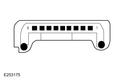
Refer to Wiring Diagrams Cell 134 for schematic and connector information. Normal Operation and Fault Conditions
REFER to: Information and Entertainment System - Component Location
(415-00 Information and Entertainment System - General Information -
Vehicles With: SYNC 4, Description and Operation). ACM Coaxial Cable Connections 
DTC Fault Trigger Conditions
Possible Sources
NOTE: Prior to carrying out diagnostics, it may be beneficial to determine the cause using the Antenna Tool Kit (refer to the Rotunda catalog for the latest part number) or equivalent tool. |
|||||||||||||||||||||
| A1 CHECK THE AUDIO SYSTEM RECEPTION WITH THE ENGINE RUNNING AND WITH THE ENGINE OFF | |||||||||||||||||||||
Does the poor reception only occur with the engine running?
|
|||||||||||||||||||||
| A2 CHECK THE GENERATOR | |||||||||||||||||||||
Is the reception OK?
|
|||||||||||||||||||||
| A3 CHECK THE IGNITION CIRCUITS | |||||||||||||||||||||
Are the ignition components OK?
|
|||||||||||||||||||||
| A4 CHECK FOR ACM (AUDIO FRONT CONTROL MODULE) ANTENNA VOLTAGE OUTPUT | |||||||||||||||||||||
|
NOTE: The AM / FM 1 antenna cable is also known as the audio unit antenna cable.
Is the voltage greater than 11 volts?
|
|||||||||||||||||||||
| A5 CHECK FOR VOLTAGE TO THE ANTENNA AMPLIFIER | |||||||||||||||||||||
Is the voltage approximately 10 volts?
|
|||||||||||||||||||||
| A6 CHECK THE AM (AMPLITUDE MODULATION) / FM (FREQUENCY MODULATION) ANTENNA AMPLIFIER | |||||||||||||||||||||
Is the reception OK?
|
|||||||||||||||||||||
| A7 CHECK FOR CORRECT ACM (AUDIO FRONT CONTROL MODULE) OPERATION | |||||||||||||||||||||
Is the concern still present?
|

 AM / FM 1 antenna cable core
|
Refer to Wiring Diagrams Cell 134 for schematic and connector information. Normal Operation and Fault Conditions
REFER to: Information and Entertainment System - Component Location
(415-00 Information and Entertainment System - General Information -
Vehicles With: SYNC 4, Description and Operation). When a satellite radio subscription is active, the ESN of the satellite radio receiver built into the ACM associates with the VIN . ACM Coaxial Cable Connections
DTC Fault Trigger Conditions
Possible Sources
NOTE: Prior to carrying out diagnostics, it may be beneficial to determine the cause using the Antenna Tool Kit (refer to the Rotunda catalog for the latest part number) or equivalent tool. NOTE: Carrying out a Master Reset of the SYNC system prior to diagnostics may resolve some satellite radio/traffic announcement concerns. |
|||||||||||||||||||||||||||
| B1 CHECK FOR DTC (DIAGNOSTIC TROUBLE CODE) U1A00:87 | |||||||||||||||||||||||||||
Is DTC U1A00:87 or U1A00:94 present?
|
|||||||||||||||||||||||||||
| B2 CHECK FOR PROMOTIONAL CHANNEL 1 | |||||||||||||||||||||||||||
Does the satellite radio system receive channel 1 with normal sound quality?
|
|||||||||||||||||||||||||||
| B3 VERIFY AN ACTIVE SUBSCRIPTION | |||||||||||||||||||||||||||
Does the display indicate the subscription has expired?
|
|||||||||||||||||||||||||||
| B4 CHECK THE VEHICLE SERVICE HISTORY FOR ACM (AUDIO FRONT CONTROL MODULE) REPLACEMENT | |||||||||||||||||||||||||||
Does the vehicle service history indicate the ACM was recently replaced?
|
|||||||||||||||||||||||||||
| B5 VERIFY THE VIN (VEHICLE IDENTIFICATION NUMBER) AND THE ESN (ELECTRONIC SERIAL NUMBER) ON FILE MATCHES THE VIN (VEHICLE IDENTIFICATION NUMBER) AND THE ESN (ELECTRONIC SERIAL NUMBER) FROM THE VEHICLE | |||||||||||||||||||||||||||
Does the VIN and the ESN on the SIRIUS customer file match the ESN and VIN retrieved from the vehicle?
|
|||||||||||||||||||||||||||
| B6 CHECK THE CONNECTIVITY SETTINGS USING THE TOUCHSCREEN DISPLAY UNIT | |||||||||||||||||||||||||||
Are the Vehicle Connectivity and the SiriusXM with 360L settings enabled?
|
|||||||||||||||||||||||||||
| B7 CHECK FOR GWM (GATEWAY MODULE A) DIAGNOSTIC TROUBLE CODES (DTCS) | |||||||||||||||||||||||||||
Are any GWM Diagnostic Trouble Codes (DTCs) present?
|
|||||||||||||||||||||||||||
| B8 CHECK THE CELLULAR SIGNAL STRENGTH | |||||||||||||||||||||||||||
Does the display indicate a good cellular strength signal of at least 2 bars?
|
|||||||||||||||||||||||||||
| B9 VERIFY THE VIN (VEHICLE IDENTIFICATION NUMBER) AND THE ESN (ELECTRONIC SERIAL NUMBER) ON FILE MATCHES THE VIN (VEHICLE IDENTIFICATION NUMBER) AND THE ESN (ELECTRONIC SERIAL NUMBER) FROM THE VEHICLE | |||||||||||||||||||||||||||
Does the satellite radio system receive multiple channels with normal sound quality?
|
|||||||||||||||||||||||||||
| B10 CHECK FOR CORRECT ACM (AUDIO FRONT CONTROL MODULE) OUTPUT VOLTAGE TO THE SATELLITE RADIO ANTENNA CABLE | |||||||||||||||||||||||||||
Is the voltage between 4.7 and 5.8 volts?
|
|||||||||||||||||||||||||||
| B11 CHECK FOR VOLTAGE TO THE GPS (GLOBAL POSITIONING SYSTEM) /SATELLITE RADIO ANTENNA | |||||||||||||||||||||||||||
Is the voltage between 4.7 and 5.8 volts?
|
|||||||||||||||||||||||||||
| B12 ISOLATE THE GPS (GLOBAL POSITIONING SYSTEM) /SATELLITE RADIO ANTENNA SPLITTER CABLE | |||||||||||||||||||||||||||
Does the system in question operate correctly?
|
|||||||||||||||||||||||||||
| B13 CHECK THE ANTENNA BASE AND MOUNTING SURFACE | |||||||||||||||||||||||||||
Is antenna base and mounting free of corrosion?
|
|||||||||||||||||||||||||||
| B14 VERIFY THE COMPASS OPERATES CORRECTLY | |||||||||||||||||||||||||||
Does the compass operate correctly?
|
|||||||||||||||||||||||||||
| B15 ISOLATE THE GPS (GLOBAL POSITIONING SYSTEM) /SATELLITE RADIO ANTENNA | |||||||||||||||||||||||||||
Does the system in question operate correctly?
|
|||||||||||||||||||||||||||
| B16 CHECK THE SERIAL DATA CIRCUITS FOR A SHORT TO GROUND | |||||||||||||||||||||||||||
Are the resistances greater than 10,000 ohms?
|
|||||||||||||||||||||||||||
| B17 CHECK THE SERIAL DATA CIRCUITS FOR A SHORT TO VOLTAGE | |||||||||||||||||||||||||||
Is any voltage present?
|
|||||||||||||||||||||||||||
| B18 CHECK THE SERIAL DATA CIRCUITS FOR A SHORT TOGETHER | |||||||||||||||||||||||||||
Is the resistance greater than 10,000 ohms?
|
|||||||||||||||||||||||||||
| B19 CHECK THE SERIAL DATA CIRCUITS FOR AN OPEN | |||||||||||||||||||||||||||
Are the resistances less than 3 ohms?
|
|||||||||||||||||||||||||||
| B20 CHECK FOR CORRECT ACM (AUDIO FRONT CONTROL MODULE) OPERATION | |||||||||||||||||||||||||||
Is the concern still present?
|
|||||||||||||||||||||||||||
| B21 CHECK FOR CORRECT APIM (SYNC MODULE) OPERATION | |||||||||||||||||||||||||||
Is the concern still present?
|
 GPS antenna cable core at the roof mounted antenna, pin 1

|
Refer to Wiring Diagrams Cell 134 for schematic and connector information. Normal Operation and Fault Conditions
REFER to: Information and Entertainment System - System Operation and
Component Description (415-00 Information and Entertainment System -
General Information - Vehicles With: SYNC 4, Description and Operation). A short to ground or voltage in the circuitry to one of the speakers may cause multiple speakers to lose sound due to the built-in overload protection feature of the ACM . In this case, a speaker fault DTC sets. DTC Fault Trigger Conditions
Possible Sources
|
|||||||||||||||||||||||||||||||||||||||||||||
| C1 VERIFY THE ACM (AUDIO FRONT CONTROL MODULE) PASSES THE NETWORK TEST | |||||||||||||||||||||||||||||||||||||||||||||
Does the ACM pass the network test?
|
|||||||||||||||||||||||||||||||||||||||||||||
| C2 VERIFY THE APIM (SYNC MODULE) PASSES THE NETWORK TEST | |||||||||||||||||||||||||||||||||||||||||||||
Does the APIM pass the network test?
|
|||||||||||||||||||||||||||||||||||||||||||||
| C3 VERIFY THE DSP (AUDIO DIGITAL SIGNAL PROCESSING MODULE) PASSES THE NETWORK TEST | |||||||||||||||||||||||||||||||||||||||||||||
Does the DSP pass the network test?
|
|||||||||||||||||||||||||||||||||||||||||||||
| C4 CHECK FOR APIM (SYNC MODULE) DIAGNOSTIC TROUBLE CODES (DTCS) | |||||||||||||||||||||||||||||||||||||||||||||
Are any Diagnostic Trouble Codes (DTCs) present?
|
|||||||||||||||||||||||||||||||||||||||||||||
| C5 CHECK FOR ACM (AUDIO FRONT CONTROL MODULE) DIAGNOSTIC TROUBLE CODES (DTCS) | |||||||||||||||||||||||||||||||||||||||||||||
Are any Diagnostic Trouble Codes (DTCs) present?
|
|||||||||||||||||||||||||||||||||||||||||||||
| C6 CHECK FOR DSP (AUDIO DIGITAL SIGNAL PROCESSING MODULE) SPEAKER-RELATED DIAGNOSTIC TROUBLE CODES (DTCS) | |||||||||||||||||||||||||||||||||||||||||||||
Are any speaker-related Diagnostic Trouble Codes (DTCs) present?
|
|||||||||||||||||||||||||||||||||||||||||||||
| C7 CHECK THE DSP (AUDIO DIGITAL SIGNAL PROCESSING MODULE) ENABLE CIRCUIT FOR CORRECT VOLTAGE | |||||||||||||||||||||||||||||||||||||||||||||
Is the voltage between 3.5 and 7 volts?
|
|||||||||||||||||||||||||||||||||||||||||||||
| C8 CHECK THE DSP (AUDIO DIGITAL SIGNAL PROCESSING MODULE) ENABLE CIRCUIT FOR A SHORT TO GROUND | |||||||||||||||||||||||||||||||||||||||||||||
Is the resistance greater than 10,000 ohms?
|
|||||||||||||||||||||||||||||||||||||||||||||
| C9 CHECK THE DSP (AUDIO DIGITAL SIGNAL PROCESSING MODULE) ENABLE CIRCUIT FOR A SHORT TO VOLTAGE | |||||||||||||||||||||||||||||||||||||||||||||
Is any voltage present?
|
|||||||||||||||||||||||||||||||||||||||||||||
| C10 CHECK THE DSP (AUDIO DIGITAL SIGNAL PROCESSING MODULE) ENABLE CIRCUIT FOR AN OPEN | |||||||||||||||||||||||||||||||||||||||||||||
Is the resistance less than 3 ohms?
|
|||||||||||||||||||||||||||||||||||||||||||||
| C11 CHECK THE ACM (AUDIO FRONT CONTROL MODULE) CONFIGURATION | |||||||||||||||||||||||||||||||||||||||||||||
Is sound heard from all of the speakers?
|
|||||||||||||||||||||||||||||||||||||||||||||
| C12 CHECK THE DSP (AUDIO DIGITAL SIGNAL PROCESSING MODULE) CONFIGURATION | |||||||||||||||||||||||||||||||||||||||||||||
Is sound heard from all of the speakers?
|
|||||||||||||||||||||||||||||||||||||||||||||
| C13 CHECK THE REAR AUTOMOBILE AUDIO BUS (A2B) CABLE | |||||||||||||||||||||||||||||||||||||||||||||
Is sound heard from all of the speakers?
|
|||||||||||||||||||||||||||||||||||||||||||||
| C14 CHECK THE CENTER AUTOMOBILE AUDIO BUS (A2B) CABLE | |||||||||||||||||||||||||||||||||||||||||||||
Is sound heard from all of the speakers?
|
|||||||||||||||||||||||||||||||||||||||||||||
| C15 CHECK THE FRONT AUTOMOBILE AUDIO BUS (A2B) CABLE | |||||||||||||||||||||||||||||||||||||||||||||
Is sound heard from all of the speakers?
|
|||||||||||||||||||||||||||||||||||||||||||||
| C16 CHECK FOR CORRECT DSP (AUDIO DIGITAL SIGNAL PROCESSING MODULE) OPERATION | |||||||||||||||||||||||||||||||||||||||||||||
Is the concern still present?
|
|||||||||||||||||||||||||||||||||||||||||||||
| C17 CHECK FOR CORRECT ACM (AUDIO FRONT CONTROL MODULE) OPERATION | |||||||||||||||||||||||||||||||||||||||||||||
Is the concern still present?
|
|
Normal Operation and Fault Conditions
REFER to: Information and Entertainment System - System Operation and
Component Description (415-00 Information and Entertainment System -
General Information - Vehicles With: SYNC 4, Description and Operation). Possible Sources
Visual Inspection and Pre-checks
|
||||
| D1 ISOLATE THE ZONE | ||||
Does applying pressure to a trim panel reduce or eliminate the noise?
|
||||
| D2 REMOVE AND INSPECT BEHIND/UNDERNEATH THE SUSPECT TRIM PANEL | ||||
Is the source of the noise located?
|
||||
| D3 CHECK THE SUSPECT SPEAKER FOR WATER INTRUSION | ||||
Are any watermarks present on the speaker?
|
||||
| D4 ISOLATE THE SUSPECT SPEAKER TO VERIFY NOISE | ||||
Is the noise still present in the suspect speaker?
|
|
Normal Operation and Fault Conditions
REFER to: Information and Entertainment System - System Operation and
Component Description (415-00 Information and Entertainment System -
General Information - Vehicles With: SYNC 4, Description and Operation). Possible Sources
|
||||
| E1 CHECK THE SPEED COMPENSATED VOLUME SETTING | ||||
|
NOTE: Refer to the Owner Literature to access the speed compensated volume settings.
Does the volume remain constant with the speed compensated volume turned off, and increase and decrease with vehicle speed with the speed compensated volume set to maximum?
|
||||
| E2 CHECK FOR COMMUNICATION DIAGNOSTIC TROUBLE CODES (DTCS) | ||||
Are any Diagnostic Trouble Codes (DTCs) present?
|
||||
| E3 CARRY OUT PMI (PROGRAMMABLE MODULE INSTALLATION) FOR THE SUSPECT MODULE | ||||
Does the speed compensated volume feature operate?
|
||||
| E4 CHECK FOR CORRECT DSP (AUDIO DIGITAL SIGNAL PROCESSING MODULE) OPERATION | ||||
Is the concern still present?
|
|
Refer to Wiring Diagrams Cell 134 for schematic and connector information. Normal Operation and Fault Conditions
REFER to: Information and Entertainment System - Component Location
(415-00 Information and Entertainment System - General Information -
Vehicles With: SYNC 4, Description and Operation). DTC Fault Trigger Conditions
Possible Sources
NOTE: The rear door woofer speaker and corresponding door tweeter speaker share the same circuitry. If a concern exists with both speakers, retest the system with the tweeter speaker disconnected to determine if the tweeter speaker is the cause of the concern. |
|||||||||||||||||||||||||||||||||||||||||||||||||||||||||||||||||||||||||||||||||||||||||||||||||||||||||||||||||||||||||||||||||||||||||||||||||||
| F1 CHECK FOR ACM (AUDIO FRONT CONTROL MODULE) DIAGNOSTIC TROUBLE CODES (DTCS) | |||||||||||||||||||||||||||||||||||||||||||||||||||||||||||||||||||||||||||||||||||||||||||||||||||||||||||||||||||||||||||||||||||||||||||||||||||
Are any Diagnostic Trouble Codes (DTCs) present?
|
|||||||||||||||||||||||||||||||||||||||||||||||||||||||||||||||||||||||||||||||||||||||||||||||||||||||||||||||||||||||||||||||||||||||||||||||||||
| F2 CHECK THE AUDIO CIRCUITS TO THE SPEAKER FOR A SHORT TO GROUND | |||||||||||||||||||||||||||||||||||||||||||||||||||||||||||||||||||||||||||||||||||||||||||||||||||||||||||||||||||||||||||||||||||||||||||||||||||
|
NOTE: For a rear door tweeter speaker concern, make sure the corresponding door woofer speaker is disconnected.
Are the resistances greater than 10,000 ohms?
|
|||||||||||||||||||||||||||||||||||||||||||||||||||||||||||||||||||||||||||||||||||||||||||||||||||||||||||||||||||||||||||||||||||||||||||||||||||
| F3 CHECK THE AUDIO CIRCUITS TO THE SPEAKER FOR A SHORT TO VOLTAGE | |||||||||||||||||||||||||||||||||||||||||||||||||||||||||||||||||||||||||||||||||||||||||||||||||||||||||||||||||||||||||||||||||||||||||||||||||||
Is any voltage present?
|
|||||||||||||||||||||||||||||||||||||||||||||||||||||||||||||||||||||||||||||||||||||||||||||||||||||||||||||||||||||||||||||||||||||||||||||||||||
| F4 CHECK THE AUDIO CIRCUITS TO THE SPEAKER FOR A SHORT TOGETHER | |||||||||||||||||||||||||||||||||||||||||||||||||||||||||||||||||||||||||||||||||||||||||||||||||||||||||||||||||||||||||||||||||||||||||||||||||||
Are the resistances greater than 10,000 ohms?
|
|||||||||||||||||||||||||||||||||||||||||||||||||||||||||||||||||||||||||||||||||||||||||||||||||||||||||||||||||||||||||||||||||||||||||||||||||||
| F5 CHECK THE AUDIO CIRCUITS TO THE SPEAKER FOR AN OPEN | |||||||||||||||||||||||||||||||||||||||||||||||||||||||||||||||||||||||||||||||||||||||||||||||||||||||||||||||||||||||||||||||||||||||||||||||||||
Are the resistances less than 3 ohms?
|
|||||||||||||||||||||||||||||||||||||||||||||||||||||||||||||||||||||||||||||||||||||||||||||||||||||||||||||||||||||||||||||||||||||||||||||||||||
| F6 CHECK THE AUDIO SIGNAL TO THE SUSPECT SPEAKER | |||||||||||||||||||||||||||||||||||||||||||||||||||||||||||||||||||||||||||||||||||||||||||||||||||||||||||||||||||||||||||||||||||||||||||||||||||
|
NOTE: For a rear door tweeter speaker concern, make sure the corresponding door woofer speaker is connected.
Is a fluctuating AC voltage present?
|
|||||||||||||||||||||||||||||||||||||||||||||||||||||||||||||||||||||||||||||||||||||||||||||||||||||||||||||||||||||||||||||||||||||||||||||||||||
| F7 CHECK FOR CORRECT DSP (AUDIO DIGITAL SIGNAL PROCESSING MODULE) OPERATION | |||||||||||||||||||||||||||||||||||||||||||||||||||||||||||||||||||||||||||||||||||||||||||||||||||||||||||||||||||||||||||||||||||||||||||||||||||
Is the concern still present?
|

|
Refer to Wiring Diagrams Cell 134 for schematic and connector information. Normal Operation and Fault Conditions
REFER to: Information and Entertainment System - Component Location
(415-00 Information and Entertainment System - General Information -
Vehicles With: SYNC 4, Description and Operation). DTC Fault Trigger Conditions
Possible Sources
NOTE: The rear door speaker and corresponding door tweeter speaker share the same circuitry. If a concern exists with both speakers, retest the system with the tweeter speaker disconnected to determine if the tweeter speaker is the cause of the concern. |
|||||||||||||||||||||||||||||||||||||||||||||||||||||||||||||||||||||||||||||||||||||||||||||||||||||||||||||||||||||||||||||||||||||||||||||||||||||||||||||||||||||||||||||||||||||||||||||||||||||||||||||||||||||||||||||||||||||||||||||||||||
| G1 CHECK FOR ACM (AUDIO FRONT CONTROL MODULE) DIAGNOSTIC TROUBLE CODES (DTCS) | |||||||||||||||||||||||||||||||||||||||||||||||||||||||||||||||||||||||||||||||||||||||||||||||||||||||||||||||||||||||||||||||||||||||||||||||||||||||||||||||||||||||||||||||||||||||||||||||||||||||||||||||||||||||||||||||||||||||||||||||||||
Are any Diagnostic Trouble Codes (DTCs) present?
|
|||||||||||||||||||||||||||||||||||||||||||||||||||||||||||||||||||||||||||||||||||||||||||||||||||||||||||||||||||||||||||||||||||||||||||||||||||||||||||||||||||||||||||||||||||||||||||||||||||||||||||||||||||||||||||||||||||||||||||||||||||
| G2 CHECK THE AUDIO CIRCUITS TO THE SPEAKER FOR A SHORT TO GROUND | |||||||||||||||||||||||||||||||||||||||||||||||||||||||||||||||||||||||||||||||||||||||||||||||||||||||||||||||||||||||||||||||||||||||||||||||||||||||||||||||||||||||||||||||||||||||||||||||||||||||||||||||||||||||||||||||||||||||||||||||||||
|
NOTE: For a rear door tweeter speaker concern, make sure the corresponding door woofer speaker is disconnected.
Are the resistances greater than 10,000 ohms?
|
|||||||||||||||||||||||||||||||||||||||||||||||||||||||||||||||||||||||||||||||||||||||||||||||||||||||||||||||||||||||||||||||||||||||||||||||||||||||||||||||||||||||||||||||||||||||||||||||||||||||||||||||||||||||||||||||||||||||||||||||||||
| G3 CHECK THE AUDIO CIRCUITS TO THE SPEAKER FOR A SHORT TO VOLTAGE | |||||||||||||||||||||||||||||||||||||||||||||||||||||||||||||||||||||||||||||||||||||||||||||||||||||||||||||||||||||||||||||||||||||||||||||||||||||||||||||||||||||||||||||||||||||||||||||||||||||||||||||||||||||||||||||||||||||||||||||||||||
Is any voltage present?
|
|||||||||||||||||||||||||||||||||||||||||||||||||||||||||||||||||||||||||||||||||||||||||||||||||||||||||||||||||||||||||||||||||||||||||||||||||||||||||||||||||||||||||||||||||||||||||||||||||||||||||||||||||||||||||||||||||||||||||||||||||||
| G4 CHECK THE AUDIO CIRCUITS TO THE SPEAKER FOR A SHORT TOGETHER | |||||||||||||||||||||||||||||||||||||||||||||||||||||||||||||||||||||||||||||||||||||||||||||||||||||||||||||||||||||||||||||||||||||||||||||||||||||||||||||||||||||||||||||||||||||||||||||||||||||||||||||||||||||||||||||||||||||||||||||||||||
Are the resistances greater than 10,000 ohms?
|
|||||||||||||||||||||||||||||||||||||||||||||||||||||||||||||||||||||||||||||||||||||||||||||||||||||||||||||||||||||||||||||||||||||||||||||||||||||||||||||||||||||||||||||||||||||||||||||||||||||||||||||||||||||||||||||||||||||||||||||||||||
| G5 CHECK THE AUDIO CIRCUITS TO THE SPEAKER FOR AN OPEN | |||||||||||||||||||||||||||||||||||||||||||||||||||||||||||||||||||||||||||||||||||||||||||||||||||||||||||||||||||||||||||||||||||||||||||||||||||||||||||||||||||||||||||||||||||||||||||||||||||||||||||||||||||||||||||||||||||||||||||||||||||
Are the resistances less than 3 ohms?
|
|||||||||||||||||||||||||||||||||||||||||||||||||||||||||||||||||||||||||||||||||||||||||||||||||||||||||||||||||||||||||||||||||||||||||||||||||||||||||||||||||||||||||||||||||||||||||||||||||||||||||||||||||||||||||||||||||||||||||||||||||||
| G6 CHECK THE AUDIO SIGNAL TO THE SUSPECT SPEAKER | |||||||||||||||||||||||||||||||||||||||||||||||||||||||||||||||||||||||||||||||||||||||||||||||||||||||||||||||||||||||||||||||||||||||||||||||||||||||||||||||||||||||||||||||||||||||||||||||||||||||||||||||||||||||||||||||||||||||||||||||||||
Is a fluctuating AC voltage present?
|
|||||||||||||||||||||||||||||||||||||||||||||||||||||||||||||||||||||||||||||||||||||||||||||||||||||||||||||||||||||||||||||||||||||||||||||||||||||||||||||||||||||||||||||||||||||||||||||||||||||||||||||||||||||||||||||||||||||||||||||||||||
| G7 CHECK FOR CORRECT DSP (AUDIO DIGITAL SIGNAL PROCESSING MODULE) OPERATION | |||||||||||||||||||||||||||||||||||||||||||||||||||||||||||||||||||||||||||||||||||||||||||||||||||||||||||||||||||||||||||||||||||||||||||||||||||||||||||||||||||||||||||||||||||||||||||||||||||||||||||||||||||||||||||||||||||||||||||||||||||
Is the concern still present?
|
|
Refer to Wiring Diagrams Cell 134 for schematic and connector information. Normal Operation and Fault Conditions
REFER to: Information and Entertainment System - System Operation and
Component Description (415-00 Information and Entertainment System -
General Information - Vehicles With: SYNC 4, Description and Operation). Possible Sources
|
||||
| H1 VERIFY THE ACM (AUDIO FRONT CONTROL MODULE) , THE APIM (SYNC MODULE) AND THE FCIM (FRONT CONTROLS INTERFACE MODULE) PASS THE NETWORK TEST | ||||
Does the ACM , the APIM and the FCIM pass the network test?
|
||||
| H2 CHECK FOR ACM (AUDIO FRONT CONTROL MODULE) DIAGNOSTIC TROUBLE CODES (DTCS) | ||||
Are any Diagnostic Trouble Codes (DTCs) present?
|
||||
| H3 CHECK FOR APIM (SYNC MODULE) DIAGNOSTIC TROUBLE CODES (DTCS) | ||||
Are any Diagnostic Trouble Codes (DTCs) present?
|
||||
| H4 CHECK FOR FCIM (FRONT CONTROLS INTERFACE MODULE) DIAGNOSTIC TROUBLE CODES (DTCS) | ||||
Are any Diagnostic Trouble Codes (DTCs) present?
|
||||
| H5 CHECK FOR CORRECT FCIM (FRONT CONTROLS INTERFACE MODULE) OPERATION | ||||
Is the concern still present?
|
|
Refer to Wiring Diagrams Cell 134 for schematic and connector information. Normal Operation and Fault Conditions
REFER to: Information and Entertainment System - System Operation and
Component Description (415-00 Information and Entertainment System -
General Information - Vehicles With: SYNC 4, Description and Operation). DTC Fault Trigger Conditions
Possible Sources
|
||||||||||||||||||||||||||||||||||
| I1 CHECK FOR SCCM (STEERING COLUMN CONTROL MODULE) COMMUNICATION | ||||||||||||||||||||||||||||||||||
Does the SCCM pass the network test?
|
||||||||||||||||||||||||||||||||||
| I2 CHECK FOR VOLTAGE TO THE STEERING WHEEL SWITCH | ||||||||||||||||||||||||||||||||||
Are the voltages approximately 5 volts?
|
||||||||||||||||||||||||||||||||||
| I3 CHECK THE STEERING WHEEL HARNESS | ||||||||||||||||||||||||||||||||||
Are the voltages approximately 5 volts?
|
||||||||||||||||||||||||||||||||||
| I4 CHECK THE CLOCKSPRING FOR AN OPEN | ||||||||||||||||||||||||||||||||||
Are the resistances less than 3 ohms?
|
||||||||||||||||||||||||||||||||||
| I5 CHECK FOR CORRECT SCCM (STEERING COLUMN CONTROL MODULE) OPERATION | ||||||||||||||||||||||||||||||||||
Is the concern still present?
|
 Upper Clockspring C218B, pin 7 (component side)
 Lower clockspring connection, pin 1 (component side)
|
NOTE: The display unit calibrates after each ignition cycle. Touching the display during an ignition cycle may cause the touchscreen to be inoperative. Refer to Wiring Diagrams Cell 134 for schematic and connector information. Normal Operation and Fault Conditions
REFER to: Information and Entertainment System - System Operation and
Component Description (415-00 Information and Entertainment System -
General Information - Vehicles With: SYNC 4, Description and Operation). DTC Fault Trigger Conditions
Possible Sources
NOTE: Prior to carrying out diagnostics, it may be beneficial to determine the cause using the Circuit Tester and LVDS Adapter Kit 420-912 (Rotunda part number NUD420-912) or equivalent tool. |
||||||||||||||||||||||||
 COMPLETE THE FDRS GUIDED ROUTINE COMPLETE THE FDRS GUIDED ROUTINE |
||||||||||||||||||||||||
|
 To
complete the diagnosis, navigate to the FDRS Guided Routine tab and
carry out the procedure SYNC Touchscreen/Information and Entertainment
Display.
To
complete the diagnosis, navigate to the FDRS Guided Routine tab and
carry out the procedure SYNC Touchscreen/Information and Entertainment
Display.
|
Refer to Wiring Diagrams Cell 134 for schematic and connector information. Normal Operation and Fault Conditions
REFER to: Information and Entertainment System - System Operation and
Component Description (415-00 Information and Entertainment System -
General Information - Vehicles With: SYNC 4, Description and Operation). Possible Sources
|
||||||||||||||||||||||||||||||||||||||||
| K1 CHECK THE OPERATION OF THE SPEAKERS USING THE AM (AMPLITUDE MODULATION) / FM (FREQUENCY MODULATION) MODE | ||||||||||||||||||||||||||||||||||||||||
Do all of the speakers operate?
|
||||||||||||||||||||||||||||||||||||||||
| K2 CHECK THE STEERING WHEEL SWITCH PARAMETER IDENTIFICATIONS (PIDS) | ||||||||||||||||||||||||||||||||||||||||
Do the Parameter Identifications (PIDs) correspond correctly?
|
||||||||||||||||||||||||||||||||||||||||
| K3 CHECK THE APIM (SYNC MODULE) OUTPUT CIRCUITS FOR A SHORT TO GROUND | ||||||||||||||||||||||||||||||||||||||||
Are the resistances greater than 10,000 ohms?
|
||||||||||||||||||||||||||||||||||||||||
| K4 CHECK THE APIM (SYNC MODULE) OUTPUT CIRCUITS FOR A SHORT TO VOLTAGE | ||||||||||||||||||||||||||||||||||||||||
Is any voltage present?
|
||||||||||||||||||||||||||||||||||||||||
| K5 CHECK THE APIM (SYNC MODULE) OUTPUT CIRCUITS FOR A SHORT TOGETHER | ||||||||||||||||||||||||||||||||||||||||
Are the resistances greater than 10,000 ohms?
|
||||||||||||||||||||||||||||||||||||||||
| K6 CHECK THE APIM (SYNC MODULE) OUTPUT CIRCUITS FOR AN OPEN | ||||||||||||||||||||||||||||||||||||||||
Are the resistances less than 3 ohms?
|
||||||||||||||||||||||||||||||||||||||||
| K7 CHECK FOR AN AC (ALTERNATING CURRENT) VOLTAGE SIGNAL FROM THE APIM (SYNC MODULE) OUTPUT CIRCUITS | ||||||||||||||||||||||||||||||||||||||||
Is a fluctuating AC voltage present?
|
||||||||||||||||||||||||||||||||||||||||
| K8 CHECK FOR CORRECT APIM (SYNC MODULE) OPERATION | ||||||||||||||||||||||||||||||||||||||||
Is the concern still present?
|
||||||||||||||||||||||||||||||||||||||||
| K9 CHECK FOR CORRECT ACM (AUDIO FRONT CONTROL MODULE) OPERATION | ||||||||||||||||||||||||||||||||||||||||
Is the concern still present?
|
|
Refer to Wiring Diagrams Cell 134 for schematic and connector information. Normal Operation and Fault Conditions
REFER to: Information and Entertainment System - Component Location
(415-00 Information and Entertainment System - General Information -
Vehicles With: SYNC 4, Description and Operation). DTC Fault Trigger Conditions
Possible Sources
|
||||||||||||
| COMPLETE THE FDRS GUIDED ROUTINE |
||||||||||||
|
|
Normal Operation and Fault Conditions
REFER to: Information and Entertainment System - System Operation and
Component Description (415-00 Information and Entertainment System -
General Information - Vehicles With: SYNC 4, Description and Operation). Possible Sources
NOTE: The Wake Word used by the vehicle owner needs to be provided in advance of this test. |
||||
| M1 CHECK THE OPERATION OF THE STEERING WHEEL VOICE BUTTON | ||||
Does the SYNC system acknowledge the voice button press?
|
||||
| M2 CHECK THE OPERATION OF THE MICROPHONE | ||||
Does the radio change to FM?
|
||||
| M3 CHECK THE WAKE WORD SETTINGS | ||||
Is the Listen for Wake Word setting enabled?
|
||||
| M4 CHECK THE PREFERRED WAKE WORD | ||||
Does the Preferred Wake Word match the wake word provided by the vehicle owner?
|
|
Refer to Wiring Diagrams Cell 134 for schematic and connector information. Normal Operation and Fault Conditions
REFER to: Information and Entertainment System - Component Location
(415-00 Information and Entertainment System - General Information -
Vehicles With: SYNC 4, Description and Operation). DTC Fault Trigger Conditions
Possible Sources
|
||||||||||||
| COMPLETE THE FDRS GUIDED ROUTINE |
||||||||||||
|
|
Normal Operation and Fault Conditions
REFER to: Information and Entertainment System - System Operation and
Component Description (415-00 Information and Entertainment System -
General Information - Vehicles With: SYNC 4, Description and Operation). Possible Sources
|
| COMPLETE THE FDRS GUIDED ROUTINE |
|
|
Normal Operation and Fault Conditions
REFER to: Information and Entertainment System - System Operation and
Component Description (415-00 Information and Entertainment System -
General Information - Vehicles With: SYNC 4, Description and Operation). If a fault message appears indicating the 911 Assist or emergency assistance is not operational, the concern may be caused due to modules not communicating or incorrect APIM programming procedures. Possible Sources
|
||||
| P1 VERIFY THE 911 ASSIST OR EMERGENCY ASSISTANCE FEATURE IS ENABLED | ||||
Is the 911 Assist or emergency assistance setting enabled?
|
||||
| P2 CHECK FOR CONTINUOUS MEMORY DIAGNOSTIC TROUBLE CODES (CMDTCS) | ||||
Are any Continuous Memory Diagnostic Trouble Codes (CMDTCs) present?
|
||||
| P3 CHECK THE VEHICLE SERVICE HISTORY | ||||
Is any recent service action noted with the RCM or the APIM noted?
|
||||
| P4 CHECK FOR CORRECT APIM (SYNC MODULE) OPERATION | ||||
Is the concern still present?
|
|
Normal Operation and Fault Conditions
REFER to: Information and Entertainment System - System Operation and
Component Description (415-00 Information and Entertainment System -
General Information - Vehicles With: SYNC 4, Description and Operation). Possible Sources
|
| COMPLETE THE FDRS GUIDED ROUTINE |
|
|
Normal Operation and Fault Conditions
REFER to: Information and Entertainment System - System Operation and
Component Description (415-00 Information and Entertainment System -
General Information - Vehicles With: SYNC 4, Description and Operation).
Possible Sources
|
| Diagnostic steps are not provided for this symptom or DTC. REFER to: Diagnostic Methods (100-00 General Information, Description and Operation). |
|
Refer to Wiring Diagrams Cell 134 for schematic and connector information. Normal Operation and Fault Conditions
REFER to: Information and Entertainment System - Component Location
(415-00 Information and Entertainment System - General Information -
Vehicles With: SYNC 4, Description and Operation). ACM Antenna Cable Connections
APIM Coaxial Cable Connections 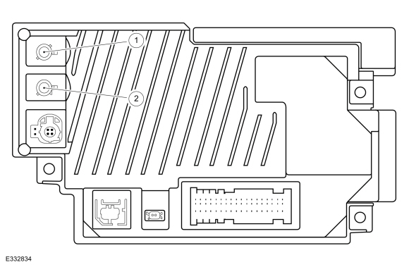
DTC Fault Trigger Conditions
Possible Sources
NOTE: Prior to carrying out diagnostics, it may be beneficial to determine the cause using the Antenna Tool Kit (refer to the Rotunda catalog for the latest part number) or equivalent tool. NOTE: Carrying out a Master Reset of the SYNC system prior to diagnostics may resolve some compass/navigation concerns. |
||||||||||||||||||||||||||||||
| S1 CHECK FOR ABS (ANTI-LOCK BRAKE SYSTEM) MODULE NETWORK COMMUNICATION | ||||||||||||||||||||||||||||||
Is DTC U0121:00 present?
|
||||||||||||||||||||||||||||||
| S2 CHECK THE GPS (GLOBAL POSITIONING SYSTEM) ANTENNA RECEPTION | ||||||||||||||||||||||||||||||
Are 3 or more satellites displayed for "Number of Satellites" and is "3D" displayed for "fix Mode"?
|
||||||||||||||||||||||||||||||
| S3 CHECK COMPASS FOR CORRECT OPERATION | ||||||||||||||||||||||||||||||
Does the compass operate correctly?
|
||||||||||||||||||||||||||||||
| S4 CHECK FOR CORRECT APIM (SYNC MODULE) OUTPUT VOLTAGE AT THE GPS (GLOBAL POSITIONING SYSTEM) CABLE CONNECTION | ||||||||||||||||||||||||||||||
Is the voltage between 4.7 and 5.8 volts?
|
||||||||||||||||||||||||||||||
| S5 CHECK FOR PROMOTIONAL CHANNEL 1 | ||||||||||||||||||||||||||||||
Does the satellite radio system receive channel 1 with normal sound quality?
|
||||||||||||||||||||||||||||||
| S6 CHECK FOR CORRECT ACM (AUDIO FRONT CONTROL MODULE) OUTPUT VOLTAGE TO THE SATELLITE RADIO ANTENNA CABLE | ||||||||||||||||||||||||||||||
Is the voltage between 4.7 and 5.8 volts?
|
||||||||||||||||||||||||||||||
| S7 CHECK FOR VOLTAGE TO THE GPS (GLOBAL POSITIONING SYSTEM) /SATELLITE RADIO ANTENNA | ||||||||||||||||||||||||||||||
Is the voltage between 4.7 and 5.8 volts?
|
||||||||||||||||||||||||||||||
| S8 ISOLATE THE GPS (GLOBAL POSITIONING SYSTEM) /SATELLITE RADIO ANTENNA SPLITTER CABLE | ||||||||||||||||||||||||||||||
Does the compass operate correctly?
|
||||||||||||||||||||||||||||||
| S9 CHECK FOR VOLTAGE TO THE GPS (GLOBAL POSITIONING SYSTEM) ANTENNA | ||||||||||||||||||||||||||||||
Is the voltage between 4.7 and 5.8 volts?
|
||||||||||||||||||||||||||||||
| S10 CHECK THE ANTENNA BASE AND MOUNTING SURFACE | ||||||||||||||||||||||||||||||
Is antenna base and mounting free of corrosion?
|
||||||||||||||||||||||||||||||
| S11 CHECK THE ROOF MOUNTED ANTENNA | ||||||||||||||||||||||||||||||
Does the compass operate correctly?
|
||||||||||||||||||||||||||||||
| S12 CHECK FOR CORRECT ACM (AUDIO FRONT CONTROL MODULE) OPERATION | ||||||||||||||||||||||||||||||
Is the concern still present?
|
||||||||||||||||||||||||||||||
| S13 CHECK FOR CORRECT APIM (SYNC MODULE) OPERATION | ||||||||||||||||||||||||||||||
Is the concern still present?
|
|
Refer to Wiring Diagrams Cell 134 for schematic and connector information. Normal Operation and Fault Conditions
REFER to: Information and Entertainment System - Component Location
(415-00 Information and Entertainment System - General Information -
Vehicles With: SYNC 4, Description and Operation). TCU Antenna Cable Connections 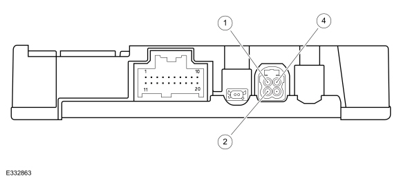
DTC Fault Trigger Conditions
Possible Sources
Visual Inspection and Pre-checks
NOTE: Prior to carrying out diagnostics, it may be beneficial to determine the cause using the Antenna Tool Kit (refer to the Rotunda catalog for the latest part number) or equivalent tool. NOTE: This pinpoint test presumes the Diagnostic Pre-Checks have been completed. |
|||||||||||||||||||||
| T1 VERIFY THE TCU (TELEMATIC CONTROL UNIT MODULE) PASSES THE NETWORK TEST | |||||||||||||||||||||
Does the TCU pass the network test?
|
|||||||||||||||||||||
| T2 CHECK FOR TCU (TELEMATIC CONTROL UNIT MODULE) DIAGNOSTIC TROUBLE CODES | |||||||||||||||||||||
Is any DTC present?
|
|||||||||||||||||||||
| T3 VERIFY THE ONBOARD SERIAL NUMBER | |||||||||||||||||||||
Is the onboard Modem Serial Number (ESN) present?
|
|||||||||||||||||||||
| T4 RESET THE TCU (TELEMATIC CONTROL UNIT MODULE) AND RECHECK FOR THE ONBOARD SERIAL NUMBER | |||||||||||||||||||||
Is the onboard Modem Serial Number (ESN) present?
|
|||||||||||||||||||||
| T5 CHECK FOR CORRECT SYSTEM OPERATION | |||||||||||||||||||||
Is concern is still present?
|
|||||||||||||||||||||
| T6 CHECK FOR UPDATED SOFTWARE | |||||||||||||||||||||
Is concern is still present?
|
|||||||||||||||||||||
| T7 CHECK THE TCU (TELEMATIC CONTROL UNIT MODULE) CELL PHONE SIGNAL STRENGTH STATUS | |||||||||||||||||||||
Is the cellular signal between -85 dBm to -95 dBm?
|
|||||||||||||||||||||
| T8 VERIFY THE TCU (TELEMATIC CONTROL UNIT MODULE) AUTHORIZATION STATUS | |||||||||||||||||||||
Is "Wait for Auth" or "Authorized" displayed?
|
|||||||||||||||||||||
| T9 CHECK IF THE TCU (TELEMATIC CONTROL UNIT MODULE) IS IN FACTORY MODE | |||||||||||||||||||||
Is "Factory Mode" displayed?
|
|||||||||||||||||||||
| T10 RECHECK IF THE TCU (TELEMATIC CONTROL UNIT MODULE) IS IN FACTORY MODE | |||||||||||||||||||||
Is "Factory Mode" still displayed?
|
|||||||||||||||||||||
| T11 RESET THE VEHICLE CONNECTIVITY SETTINGS | |||||||||||||||||||||
Is the concern still present?
|
|||||||||||||||||||||
| T12 CHECK IF THE TCU (TELEMATIC CONTROL UNIT MODULE) IS UN-PROVISIONED | |||||||||||||||||||||
Is "Un-Provisioned" displayed?
|
|||||||||||||||||||||
| T13 CHECK FOR CORRECT VEHICLE OPERATION | |||||||||||||||||||||
Does the base function in question operate when tested on the vehicle?
|
|||||||||||||||||||||
| T14 CHECK IF THE TCU (TELEMATIC CONTROL UNIT MODULE) IS AUTHORIZED | |||||||||||||||||||||
Is "Authorized" displayed?
|
|||||||||||||||||||||
| T15 CHECK IF THE TCU (TELEMATIC CONTROL UNIT MODULE) IS WAITING FOR AUTHORIZATION | |||||||||||||||||||||
Is "Waiting for Auth" displayed?
|
|||||||||||||||||||||
| T16 ADD THE VIN (VEHICLE IDENTIFICATION NUMBER) AND THEN RECHECK IF THE TCU (TELEMATIC CONTROL UNIT MODULE) IS AUTHORIZED | |||||||||||||||||||||
Is "Authorized" displayed?
|
|||||||||||||||||||||
| T17 CHECK FOR LOST COMMUNICATION DIAGNOSTIC TROUBLE CODES (DTCS) | |||||||||||||||||||||
Are any lost communication Diagnostic Trouble Codes (DTCs) set in any audio system module?
|
|||||||||||||||||||||
| T18 CARRY OUT A SYNC SYSTEM MASTER RESET | |||||||||||||||||||||
|
NOTE: Carrying out a Master Reset returns all preference settings to the factory defaults, erases the phone book and call histories, deletes any Bluetooth devices paired with the SYNC system, removes any Wi-Fi network connections (cancelling any system update download or installation in progress), erases the saved destinations (home, favorites, and previous), and deletes any devices paired with the Lincoln Way mobile application.
Is the concern still present?
|
|||||||||||||||||||||
| T19 CHECK FOR CORRECT TCU (TELEMATIC CONTROL UNIT MODULE) OUTPUT VOLTAGE TO THE PRIMARY CELLULAR ANTENNA CABLE | |||||||||||||||||||||
Does the voltage cycle from 0 to approximately 2.8 volts at regular intervals?
|
|||||||||||||||||||||
| T20 CHECK FOR VOLTAGE TO THE PRIMARY CELLULAR ANTENNA | |||||||||||||||||||||
Does the voltage cycle from 0 to approximately 2.8 volts at regular intervals?
|
|||||||||||||||||||||
| T21 CHECK FOR CORRECT TCU (TELEMATIC CONTROL UNIT MODULE) OPERATION | |||||||||||||||||||||
Is the concern still present?
|
|
Refer to Wiring Diagrams Cell 134 for schematic and connector information. Normal Operation and Fault Conditions
REFER to: Information and Entertainment System - Component Location
(415-00 Information and Entertainment System - General Information -
Vehicles With: SYNC 4, Description and Operation). TCU Antenna Cable Connections
DTC Fault Trigger Conditions
Possible Sources
NOTE: Prior to carrying out diagnostics, it may be beneficial to determine the cause using the Antenna Tool Kit (refer to the Rotunda catalog for the latest part number) or equivalent tool. |
|||||||||||||||||||||
| U1 CHECK FOR CORRECT LINCOLN WAY OPERATION | |||||||||||||||||||||
Does the Lincoln Way feature operate?
|
|||||||||||||||||||||
| U2 COMPARE THE WI-FI SPEED TO A SECOND DEVICE | |||||||||||||||||||||
Is the data speed of the vehicle 50% or less than the second device?
|
|||||||||||||||||||||
| U3 CHECK FOR TCU (TELEMATIC CONTROL UNIT MODULE) OUTPUT VOLTAGE TO THE SECONDARY CELLULAR ANTENNA CABLE | |||||||||||||||||||||
Does the voltage cycle from 0 to approximately 2.8 volts at regular intervals?
|
|||||||||||||||||||||
| U4 CHECK FOR VOLTAGE TO THE SECONDARY CELLULAR ANTENNA | |||||||||||||||||||||
Does the voltage cycle from 0 to approximately 2.8 volts at regular intervals?
|
|||||||||||||||||||||
| U5 CHECK FOR CORRECT TCU (TELEMATIC CONTROL UNIT MODULE) OPERATION | |||||||||||||||||||||
Is the concern still present?
|
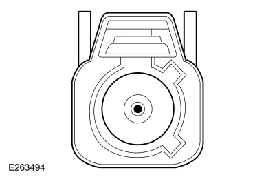 Secondary cellular antenna cable core at the antenna
|
Refer to Wiring Diagrams Cell 134 for schematic and connector information. Normal Operation and Fault Conditions
REFER to: Information and Entertainment System - Component Location
(415-00 Information and Entertainment System - General Information -
Vehicles With: SYNC 4, Description and Operation). DTC Fault Trigger Conditions
Possible Sources
Visual Inspection and Pre-checks
NOTE: The ANC system is not compatible with aftermarket audio system components and architectures not approved by Ford. |
|||||||||||||||||||||||||||||||
| V1 CHECK FOR ACM (AUDIO FRONT CONTROL MODULE) SPEAKER-RELATED DIAGNOSTIC TROUBLE CODES (DTCS) | |||||||||||||||||||||||||||||||
Are any ACM speaker-related Diagnostic Trouble Codes (DTCs) present?
|
|||||||||||||||||||||||||||||||
| V2 CHECK FOR DSP (AUDIO DIGITAL SIGNAL PROCESSING MODULE) SPEAKER-RELATED DIAGNOSTIC TROUBLE CODES (DTCS) | |||||||||||||||||||||||||||||||
Are any DSP speaker-related Diagnostic Trouble Codes (DTCs) present?
|
|||||||||||||||||||||||||||||||
| V3 INSPECT THE ANC (ACTIVE NOISE CONTROL) MICROPHONES | |||||||||||||||||||||||||||||||
Are the ANC microphones installed correctly?
|
|||||||||||||||||||||||||||||||
| V4 CHECK THE SUSPECT ANC (ACTIVE NOISE CONTROL) MICROPHONE INPUT CIRCUITS FOR A SHORT TO GROUND | |||||||||||||||||||||||||||||||
Are the resistances greater than 10,000 ohms?
|
|||||||||||||||||||||||||||||||
| V5 CHECK THE SUSPECT ANC (ACTIVE NOISE CONTROL) MICROPHONE INPUT CIRCUITS FOR A SHORT TO VOLTAGE | |||||||||||||||||||||||||||||||
Is any voltage present?
|
|||||||||||||||||||||||||||||||
| V6 CHECK THE SUSPECT ANC (ACTIVE NOISE CONTROL) MICROPHONE INPUT CIRCUITS FOR A SHORT TOGETHER | |||||||||||||||||||||||||||||||
Is the resistance greater than 10,000 ohms?
|
|||||||||||||||||||||||||||||||
| V7 CHECK THE SUSPECT ANC (ACTIVE NOISE CONTROL) MICROPHONE INPUT CIRCUITS FOR AN OPEN | |||||||||||||||||||||||||||||||
Are the resistances less than 3 ohms?
|
|||||||||||||||||||||||||||||||
| V8 CHECK FOR CORRECT ACM (AUDIO FRONT CONTROL MODULE) OPERATION | |||||||||||||||||||||||||||||||
Is the concern still present?
|
|
Refer to Wiring Diagrams Cell 134 for schematic and connector information. Normal Operation and Fault Conditions
REFER to: Information and Entertainment System - System Operation and
Component Description (415-00 Information and Entertainment System -
General Information - Vehicles With: SYNC 4, Description and Operation). Possible Sources
NOTE: Refer to the rear seat entertainment system owner manual for . |
||||
| W1 CHECK THE PASSENGER SEAT VIDEO DISPLAY VOLTAGE SUPPLY AND GROUND CIRCUITS FOR AN OPEN | ||||
Is the voltage greater than 11 volts?
|
||||
| W2 CHECK THE FAMILY ENTERTAINMENT SYSTEM COAXIAL CABLE | ||||
Is the family entertainment system coaxial cable OK?
|
|
Refer to Wiring Diagrams Cell 134 for schematic and connector information. Normal Operation and Fault Conditions
REFER to: Information and Entertainment System - System Operation and
Component Description (415-00 Information and Entertainment System -
General Information - Vehicles With: SYNC 4, Description and Operation). Possible Sources
Visual Inspection and Pre-checks
|
||||||||||
| X1 CHECK FOR BATTERY VOLTAGE TO THE FAMILY ENTERTAINMENT SYSTEM IN-LINE CONNECTOR | ||||||||||
Is the voltage greater than 11 volts?
|
||||||||||
| X2 CHECK FOR BCM (BODY CONTROL MODULE) BATTERY VOLTAGE SUPPLY CIRCUIT TO THE FAMILY ENTERTAINMENT SYSTEM FOR AN OPEN | ||||||||||
Is the resistance less than 3 ohms?
|
||||||||||
| X3 CHECK FOR ACCESSORY DELAY VOLTAGE TO THE FAMILY ENTERTAINMENT SYSTEM IN-LINE CONNECTOR | ||||||||||
Is the voltage greater than 11 volts?
|
||||||||||
| X4 CHECK THE FAMILY ENTERTAINMENT SYSTEM GROUND CIRCUIT FOR AN OPEN | ||||||||||
Is the voltage greater than 11 volts?
|
||||||||||
| X5 CHECK THE FAMILY ENTERTAINMENT SYSTEM CIRCUITS BETWEEN THE IN-LINE CONNECTOR AND THE DRIVER SEAT | ||||||||||
Is the circuitry between the in-line connector C3139 and the driver seat video display unit OK?
|
||||||||||
| X6 CHECK ACCESSORY DELAY RELAY OUTPUT CIRCUIT FOR VOLTAGE | ||||||||||
Is the voltage greater than 11 volts?
|
||||||||||
| X7 CHECK THE ACCESSORY DELAY RELAY OUTPUT CIRCUIT FOR AN OPEN | ||||||||||
Is the resistance less than 3 ohms?
|
||||||||||
| X8 CHECK THE BJB (BATTERY JUNCTION BOX) FAMILY ENTERTAINMENT SYSTEM RELAY OUTPUT CIRCUIT FOR AN OPEN | ||||||||||
Is the resistance less than 3 ohms?
|
||||||||||
| X9 CHECK FOR CORRECT BCM (BODY CONTROL MODULE) OPERATION | ||||||||||
Is the concern still present?
|
|
Normal Operation and Fault Conditions The ACM , the DSP , FCIM , the RACM and the TCU communicate with the PCM over the CAN . If messages are missing or not received from the PCM module, features such as the speed compensated volume can be inoperative. DTC Fault Trigger Conditions
Possible Sources
|
||||||||||||||||||
| Y1 VERIFY THE CONCERN | ||||||||||||||||||
Is an observable symptom present?
|
||||||||||||||||||
| Y2 CHECK THE NETWORK COMMUNICATION | ||||||||||||||||||
Does the PCM pass the network test?
|
||||||||||||||||||
| Y3 CHECK FOR NON-NETWORK DIAGNOSTIC TROUBLE CODES (DTCS) | ||||||||||||||||||
Are any non-network Diagnostic Trouble Codes (DTCs) present?
|
||||||||||||||||||
| Y4 CHECK FOR PCM (POWERTRAIN CONTROL MODULE) TROUBLE CODES (DTCS) | ||||||||||||||||||
Are any non-network Diagnostic Trouble Codes (DTCs) present?
|
||||||||||||||||||
| Y5 RECHECK FOR DTC (DIAGNOSTIC TROUBLE CODE) U0100:00 | ||||||||||||||||||
Is DTC U0100:00 still present?
|
||||||||||||||||||
| Y6 CHECK FOR OTHER CAUSES OF NETWORK COMMUNICATION CONCERN | ||||||||||||||||||
|
NOTE: If new modules were installed prior to the DTC being set, the module configuration can be incorrectly set during the PMI or the PMI may not have been carried out.
Is the observable symptom still present?
|
||||||||||||||||||
| Y7 CHECK FOR CORRECT PCM (POWERTRAIN CONTROL MODULE) OPERATION | ||||||||||||||||||
Is the concern still present?
|
|
Normal Operation and Fault Conditions The ACM communicates with the ABS module over the CAN . If messages are missing or not received from the ABS module, the GPS feature may not be accurate. DTC Fault Trigger Conditions
Possible Sources
|
||||||
| Z1 VERIFY THE CONCERN | ||||||
Is an observable symptom present?
|
||||||
| Z2 CHECK THE NETWORK COMMUNICATION | ||||||
Does the ABS module pass the network test?
|
||||||
| Z3 CHECK FOR NON-NETWORK DIAGNOSTIC TROUBLE CODES (DTCS) | ||||||
Are any non-network Diagnostic Trouble Codes (DTCs) present?
|
||||||
| Z4 CHECK FOR NON-NETWORK ABS (ANTI-LOCK BRAKE SYSTEM) MODULE DIAGNOSTIC TROUBLE CODES (DTCS) | ||||||
Are any non-network Diagnostic Trouble Codes (DTCs) present?
|
||||||
| Z5 RECHECK FOR DTC (DIAGNOSTIC TROUBLE CODE) U0121:00 | ||||||
Is DTC U0121:00 still present?
|
||||||
| Z6 CHECK FOR OTHER CAUSES OF NETWORK COMMUNICATION CONCERN | ||||||
|
NOTE: If new modules were installed prior to the DTC being set, the module configuration can be incorrectly set during the PMI or the PMI may not have been carried out.
Is the observable symptom still present?
|
||||||
| Z7 CHECK FOR CORRECT ABS (ANTI-LOCK BRAKE SYSTEM) MODULE OPERATION | ||||||
Is the concern still present?
|
|
Normal Operation and Fault Conditions The ACM , the DSP , the FCIM , RACM and the TCU communicate with the BCM over the CAN . If messages are missing or not received from the BCM , the display screen brightness may not operate not operate correctly. DTC Fault Trigger Conditions
Possible Sources
|
||||||||||||||||||
| AA1 VERIFY THE CONCERN | ||||||||||||||||||
Is an observable symptom present?
|
||||||||||||||||||
| AA2 CHECK THE NETWORK COMMUNICATION | ||||||||||||||||||
Does the BCM pass the network test?
|
||||||||||||||||||
| AA3 CHECK FOR NON-NETWORK DIAGNOSTIC TROUBLE CODES (DTCS) | ||||||||||||||||||
Are any non-network Diagnostic Trouble Codes (DTCs) present?
|
||||||||||||||||||
| AA4 CHECK FOR NON-NETWORK BCM (BODY CONTROL MODULE) DIAGNOSTIC TROUBLE CODES (DTCS) | ||||||||||||||||||
Are any non-network Diagnostic Trouble Codes (DTCs) present?
|
||||||||||||||||||
| AA5 RECHECK FOR DTC (DIAGNOSTIC TROUBLE CODE) U0140:00 | ||||||||||||||||||
Is DTC U0140:00 still present?
|
||||||||||||||||||
| AA6 CHECK FOR OTHER CAUSES OF NETWORK COMMUNICATION CONCERN | ||||||||||||||||||
|
NOTE: If new modules were installed prior to the DTC being set, the module configuration can be incorrectly set during the PMI or the PMI may not have been carried out.
Is the observable symptom still present?
|
||||||||||||||||||
| AA7 CHECK FOR CORRECT BCM (BODY CONTROL MODULE) OPERATION | ||||||||||||||||||
Is the concern still present?
|
|
Normal Operation and Fault Conditions The TCU communicates with the GWM over the CAN . If messages are missing or not received from the GWM , Ford Pass features and over the air updates may be inoperative. DTC Fault Trigger Conditions
Possible Sources
|
||||||
| AB1 VERIFY THE CONCERN | ||||||
Is an observable symptom present?
|
||||||
| AB2 CHECK THE NETWORK COMMUNICATION | ||||||
Does the GWM pass the network test?
|
||||||
| AB3 CHECK FOR NON-NETWORK DIAGNOSTIC TROUBLE CODES (DTCS) | ||||||
Are any non-network Diagnostic Trouble Codes (DTCs) present?
|
||||||
| AB4 CHECK FOR GWM (GATEWAY MODULE A) DIAGNOSTIC TROUBLE CODES (DTCS) | ||||||
Are any GWM Diagnostic Trouble Codes (DTCs) present?
|
||||||
| AB5 RECHECK FOR DTC (DIAGNOSTIC TROUBLE CODE) U0146:09 | ||||||
Is DTC U0146:09 still present?
|
||||||
| AB6 CHECK FOR OTHER CAUSES OF NETWORK COMMUNICATION CONCERN | ||||||
|
NOTE: If new modules were installed prior to the DTC being set, the module configuration can be incorrectly set during the PMI or the PMI may not have been carried out.
Is the observable symptom still present?
|
||||||
| AB7 CHECK FOR CORRECT GWM (GATEWAY MODULE A) OPERATION | ||||||
Is the concern still present?
|
|
Normal Operation and Fault Conditions The FCIM communicates with the RCM over the CAN . If messages are missing or not received from the RCM , features such as the passenger airbag disable indicator may not operate correctly. DTC Fault Trigger Conditions
Possible Sources
|
||||||
| AC1 VERIFY THE CONCERN | ||||||
Is an observable symptom present?
|
||||||
| AC2 CHECK THE NETWORK COMMUNICATION | ||||||
Does the RCM pass the network test?
|
||||||
| AC3 CHECK FOR NON-NETWORK DIAGNOSTIC TROUBLE CODES (DTCS) | ||||||
Are any non-network Diagnostic Trouble Codes (DTCs) present?
|
||||||
| AC4 CHECK FOR NON-NETWORK RCM (RESTRAINTS CONTROL MODULE) DIAGNOSTIC TROUBLE CODES (DTCS) | ||||||
Are any non-network Diagnostic Trouble Codes (DTCs) present?
|
||||||
| AC5 RECHECK FOR DTC (DIAGNOSTIC TROUBLE CODE) U0151:00 | ||||||
Is DTC U0151:00 still present?
|
||||||
| AC6 CHECK FOR OTHER CAUSES OF NETWORK COMMUNICATION CONCERN | ||||||
|
NOTE: If new modules were installed prior to the DTC being set, the module configuration can be incorrectly set during the PMI or the PMI may not have been carried out.
Is the observable symptom still present?
|
||||||
| AC7 CHECK FOR CORRECT RCM (RESTRAINTS CONTROL MODULE) OPERATION | ||||||
Is the concern still present?
|
|
Normal Operation and Fault Conditions The ACM , the DSP , FCIM and the RACM communicate with the IPC over the CAN . If messages are missing or not received from the IPC , features such as the display illumination or warning chimes may not operate correctly. DTC Fault Trigger Conditions
Possible Sources
|
|||||||||||||||
| AD1 VERIFY THE CONCERN | |||||||||||||||
Is an observable symptom present?
|
|||||||||||||||
| AD2 CHECK THE NETWORK COMMUNICATION | |||||||||||||||
Does the IPC pass the network test?
|
|||||||||||||||
| AD3 CHECK FOR NON-NETWORK DIAGNOSTIC TROUBLE CODES (DTCS) | |||||||||||||||
Are any non-network Diagnostic Trouble Codes (DTCs) present?
|
|||||||||||||||
| AD4 CHECK FOR NON-NETWORK IPC (INSTRUMENT PANEL CLUSTER) DIAGNOSTIC TROUBLE CODES (DTCS) | |||||||||||||||
Are any non-network Diagnostic Trouble Codes (DTCs) present?
|
|||||||||||||||
| AD5 RECHECK FOR DTC (DIAGNOSTIC TROUBLE CODE) U0155:00 | |||||||||||||||
Is DTC U0155:00 still present?
|
|||||||||||||||
| AD6 CHECK FOR OTHER CAUSES OF NETWORK COMMUNICATION CONCERN | |||||||||||||||
|
NOTE: If new modules were installed prior to the DTC being set, the module configuration can be incorrectly set during the PMI or the PMI may not have been carried out.
Is the observable symptom still present?
|
|||||||||||||||
| AD7 CHECK FOR CORRECT IPC (INSTRUMENT PANEL CLUSTER) OPERATION | |||||||||||||||
Is the concern still present?
|
|
Normal Operation and Fault Conditions The DSP and the RACM communicate with the ACM over the CAN . If messages are missing or not received from the ACM , the display unit may be blank. DTC Fault Trigger Conditions
Possible Sources
|
|||||||||
| AE1 VERIFY THE CONCERN | |||||||||
Is an observable symptom present?
|
|||||||||
| AE2 CHECK THE NETWORK COMMUNICATION | |||||||||
Does the ACM pass the network test?
|
|||||||||
| AE3 CHECK FOR NON-NETWORK DIAGNOSTIC TROUBLE CODES (DTCS) | |||||||||
Are any non-network Diagnostic Trouble Codes (DTCs) present?
|
|||||||||
| AE4 CHECK FOR NON-NETWORK ACM (AUDIO FRONT CONTROL MODULE) DIAGNOSTIC TROUBLE CODES (DTCS) | |||||||||
Are any non-network Diagnostic Trouble Codes (DTCs) present?
|
|||||||||
| AE5 RECHECK FOR DTC (DIAGNOSTIC TROUBLE CODE) U0184:00 | |||||||||
Is DTC U0184:00 still present?
|
|||||||||
| AE6 CHECK FOR OTHER CAUSES OF NETWORK COMMUNICATION CONCERN | |||||||||
|
NOTE: If new modules were installed prior to the DTC being set, the module configuration can be incorrectly set during the PMI or the PMI may not have been carried out.
Is the observable symptom still present?
|
|||||||||
| AE7 CHECK FOR CORRECT ACM (AUDIO FRONT CONTROL MODULE) OPERATION | |||||||||
Is the concern still present?
|
|
Normal Operation and Fault Conditions The ACM communicates with the TCU over the CAN . If messages are missing or not received from the TCU , the Lincoln Way feature may not operate correctly. DTC Fault Trigger Conditions
Possible Sources
|
||||||
| AF1 VERIFY THE CONCERN | ||||||
Is an observable symptom present?
|
||||||
| AF2 CHECK THE NETWORK COMMUNICATION | ||||||
Does the TCU pass the network test?
|
||||||
| AF3 CHECK FOR NON-NETWORK DIAGNOSTIC TROUBLE CODES (DTCS) | ||||||
Are any non-network Diagnostic Trouble Codes (DTCs) present?
|
||||||
| AF4 CHECK FOR NON-NETWORK TCU (TELEMATIC CONTROL UNIT MODULE) DIAGNOSTIC TROUBLE CODES (DTCS) | ||||||
Are any non-network Diagnostic Trouble Codes (DTCs) present?
|
||||||
| AF5 RECHECK FOR DTC (DIAGNOSTIC TROUBLE CODE) U0198:00 | ||||||
Is DTC U0198:00 still present?
|
||||||
| AF6 CHECK FOR OTHER CAUSES OF NETWORK COMMUNICATION CONCERN | ||||||
|
NOTE: If new modules were installed prior to the DTC being set, the module configuration can be incorrectly set during the PMI or the PMI may not have been carried out.
Is the observable symptom still present?
|
||||||
| AF7 CHECK FOR CORRECT TCU (TELEMATIC CONTROL UNIT MODULE) OPERATION | ||||||
Is the concern still present?
|
|
Normal Operation and Fault Conditions The RACM communicates with the SCMC (left rear multi-contour seat module) over the CAN . If messages are missing or not received from the SCMC (left rear multi-contour seat module), the left rear multi-contour seat may not operate. DTC Fault Trigger Conditions
Possible Sources
|
||||||
| AG1 VERIFY THE CONCERN | ||||||
Is an observable symptom present?
|
||||||
| AG2 CHECK THE NETWORK COMMUNICATION | ||||||
Does the SCMC (left rear seat multi-contour module) pass the network test?
|
||||||
| AG3 CHECK FOR NON-NETWORK DIAGNOSTIC TROUBLE CODES (DTCS) | ||||||
Are any non-network Diagnostic Trouble Codes (DTCs) present?
|
||||||
| AG4 CHECK FOR NON-NETWORK SCMC (LEFT REAR SEAT MULTI-CONTOUR MODULE) DIAGNOSTIC TROUBLE CODES (DTCS) | ||||||
Are any non-network Diagnostic Trouble Codes (DTCs) present?
|
||||||
| AG5 RECHECK FOR DTC (DIAGNOSTIC TROUBLE CODE) U0198:00 | ||||||
Is DTC U0198:00 still present?
|
||||||
| AG6 CHECK FOR OTHER CAUSES OF NETWORK COMMUNICATION CONCERN | ||||||
|
NOTE: If new modules were installed prior to the DTC being set, the module configuration can be incorrectly set during the PMI or the PMI may not have been carried out.
Is the observable symptom still present?
|
||||||
| AG7 CHECK FOR CORRECT SCMC (LEFT REAR SEAT MULTI-CONTOUR MODULE) OPERATION | ||||||
Is the concern still present?
|
|
Normal Operation and Fault Conditions The RACM communicates with the SCMD (right rear seat multi-contour module) over the CAN . If messages are missing or not received from the SCMD (right rear seat multi-contour module), the right rear seat multi-contour features may not operate. DTC Fault Trigger Conditions
Possible Sources
|
||||||
| AH1 VERIFY THE CONCERN | ||||||
Is an observable symptom present?
|
||||||
| AH2 CHECK THE NETWORK COMMUNICATION | ||||||
Does the SCMD (right rear seat multi-contour module) pass the network test?
|
||||||
| AH3 CHECK FOR NON-NETWORK DIAGNOSTIC TROUBLE CODES (DTCS) | ||||||
Are any non-network Diagnostic Trouble Codes (DTCs) present?
|
||||||
| AH4 CHECK FOR NON-NETWORK SCMD (RIGHT REAR SEAT MULTI-CONTOUR MODULE) DIAGNOSTIC TROUBLE CODES (DTCS) | ||||||
Are any non-network Diagnostic Trouble Codes (DTCs) present?
|
||||||
| AH5 RECHECK FOR DTC (DIAGNOSTIC TROUBLE CODE) U0211:00 | ||||||
Is DTC U0211:00 still present?
|
||||||
| AH6 CHECK FOR OTHER CAUSES OF NETWORK COMMUNICATION CONCERN | ||||||
|
NOTE: If new modules were installed prior to the DTC being set, the module configuration can be incorrectly set during the PMI or the PMI may not have been carried out.
Is the observable symptom still present?
|
||||||
| AH7 CHECK FOR CORRECT SCMD (RIGHT REAR SEAT MULTI-CONTOUR MODULE) OPERATION | ||||||
Is the concern still present?
|
|
Normal Operation and Fault Conditions The ACM and the RACM communicate with the DSP over the CAN . If messages are missing or not received from the DSP , features such as the ANC may not operate correctly. DTC Fault Trigger Conditions
Possible Sources
|
|||||||||
| AI1 VERIFY THE CONCERN | |||||||||
Is an observable symptom present?
|
|||||||||
| AI2 CHECK THE NETWORK COMMUNICATION | |||||||||
Does the DSP pass the network test?
|
|||||||||
| AI3 CHECK FOR NON-NETWORK DIAGNOSTIC TROUBLE CODES (DTCS) | |||||||||
Are any non-network Diagnostic Trouble Codes (DTCs) present?
|
|||||||||
| AI4 CHECK FOR NON-NETWORK DSP (AUDIO DIGITAL SIGNAL PROCESSING MODULE) DIAGNOSTIC TROUBLE CODES (DTCS) | |||||||||
Are any non-network Diagnostic Trouble Codes (DTCs) present?
|
|||||||||
| AI5 RECHECK FOR DTC (DIAGNOSTIC TROUBLE CODE) U0238:00 | |||||||||
Is DTC U0238:00 still present?
|
|||||||||
| AI6 CHECK FOR OTHER CAUSES OF NETWORK COMMUNICATION CONCERN | |||||||||
|
NOTE: If new modules were installed prior to the DTC being set, the module configuration can be incorrectly set during the PMI or the PMI may not have been carried out.
Is the observable symptom still present?
|
|||||||||
| AI7 CHECK FOR CORRECT DSP (AUDIO DIGITAL SIGNAL PROCESSING MODULE) OPERATION | |||||||||
Is the concern still present?
|
|
Normal Operation and Fault Conditions The FCIM communicates with the RACM over the CAN . If messages are missing or not received from the RACM , the rear audio controls may be inoperative. DTC Fault Trigger Conditions
Possible Sources
|
||||||
| AJ1 VERIFY THE CONCERN | ||||||
Is an observable symptom present?
|
||||||
| AJ2 CHECK THE NETWORK COMMUNICATION | ||||||
Does the RACM pass the network test?
|
||||||
| AJ3 CHECK FOR NON-NETWORK DIAGNOSTIC TROUBLE CODES (DTCS) | ||||||
Are any non-network Diagnostic Trouble Codes (DTCs) present?
|
||||||
| AJ4 CHECK FOR NON-NETWORK RACM (REAR AUDIO CONTROL MODULE) DIAGNOSTIC TROUBLE CODES (DTCS) | ||||||
Are any non-network Diagnostic Trouble Codes (DTCs) present?
|
||||||
| AJ5 RECHECK FOR DTC (DIAGNOSTIC TROUBLE CODE) U0249:00 | ||||||
Is DTC U0249:00 still present?
|
||||||
| AJ6 CHECK FOR OTHER CAUSES OF NETWORK COMMUNICATION CONCERN | ||||||
|
NOTE: If new modules were installed prior to the DTC being set, the module configuration can be incorrectly set during the PMI or the PMI may not have been carried out.
Is the observable symptom still present?
|
||||||
| AJ7 CHECK FOR CORRECT RACM (REAR AUDIO CONTROL MODULE) OPERATION | ||||||
Is the concern still present?
|
|
Normal Operation and Fault Conditions The ACM the DSP , FCIM and the RACM communicate with the APIM over the CAN . If messages are missing or not received from the APIM , the display is blank. DTC Fault Trigger Conditions
Possible Sources
|
|||||||||||||||
| AK1 VERIFY THE CONCERN | |||||||||||||||
Is an observable symptom present?
|
|||||||||||||||
| AK2 CHECK THE NETWORK COMMUNICATION | |||||||||||||||
Does the APIM pass the network test?
|
|||||||||||||||
| AK3 CHECK FOR NON-NETWORK DIAGNOSTIC TROUBLE CODES (DTCS) | |||||||||||||||
Are any non-network Diagnostic Trouble Codes (DTCs) present?
|
|||||||||||||||
| AK4 CHECK FOR NON-NETWORK APIM (SYNC MODULE) DIAGNOSTIC TROUBLE CODES (DTCS) | |||||||||||||||
Are any non-network Diagnostic Trouble Codes (DTCs) present?
|
|||||||||||||||
| AK5 RECHECK FOR DTC (DIAGNOSTIC TROUBLE CODE) U0253:00 | |||||||||||||||
Is DTC U0253:00 still present?
|
|||||||||||||||
| AK6 CHECK FOR OTHER CAUSES OF NETWORK COMMUNICATION CONCERN | |||||||||||||||
|
NOTE: If new modules were installed prior to the DTC being set, the module configuration can be incorrectly set during the PMI or the PMI may not have been carried out.
Is the observable symptom still present?
|
|||||||||||||||
| AK7 CHECK FOR CORRECT APIM (SYNC MODULE) OPERATION | |||||||||||||||
Is the concern still present?
|
|
Normal Operation and Fault Conditions The ACM and the DSP communicate with the FCIM over the CAN . If messages are missing or not received from the FCIM , the display is blank. DTC Fault Trigger Conditions
Possible Sources
|
|||||||||
| AL1 VERIFY THE CONCERN | |||||||||
Is an observable symptom present?
|
|||||||||
| AL2 CHECK THE NETWORK COMMUNICATION | |||||||||
Does the FCIM pass the network test?
|
|||||||||
| AL3 CHECK FOR NON-NETWORK DIAGNOSTIC TROUBLE CODES (DTCS) | |||||||||
Are any non-network Diagnostic Trouble Codes (DTCs) present?
|
|||||||||
| AL4 CHECK FOR NON-NETWORK FCIM (FRONT CONTROLS INTERFACE MODULE) DIAGNOSTIC TROUBLE CODES (DTCS) | |||||||||
Are any non-network Diagnostic Trouble Codes (DTCs) present?
|
|||||||||
| AL5 RECHECK FOR DTC (DIAGNOSTIC TROUBLE CODE) U0253:00 | |||||||||
Is DTC U0253:00 still present?
|
|||||||||
| AL6 CHECK FOR OTHER CAUSES OF NETWORK COMMUNICATION CONCERN | |||||||||
|
NOTE: If new modules were installed prior to the DTC being set, the module configuration can be incorrectly set during the PMI or the PMI may not have been carried out.
Is the observable symptom still present?
|
|||||||||
| AL7 CHECK FOR CORRECT FCIM (FRONT CONTROLS INTERFACE MODULE) OPERATION | |||||||||
Is the concern still present?
|
|
Refer to Wiring Diagrams Cell 134 for schematic and connector information. Normal Operation and Fault Conditions The modules monitor the supplied voltage and set a DTC if it falls below a threshold. DTC Fault Trigger Conditions
Possible Sources
|
||||||||||||||||||||||||||||||||||||||||||||||||||||
| AM1 RECHECK FOR LOW VOLTAGE DIAGNOSTIC TROUBLE CODES (DTCS) | ||||||||||||||||||||||||||||||||||||||||||||||||||||
Is DTC U3003:16 still present?
|
||||||||||||||||||||||||||||||||||||||||||||||||||||
| AM2 CHECK FOR CHARGING SYSTEM DIAGNOSTIC TROUBLE CODES (DTCS) | ||||||||||||||||||||||||||||||||||||||||||||||||||||
Are any voltage-related Diagnostic Trouble Codes (DTCs) present?
|
||||||||||||||||||||||||||||||||||||||||||||||||||||
| AM3 CHECK THE BATTERY CONDITION AND STATE OF CHARGE | ||||||||||||||||||||||||||||||||||||||||||||||||||||
Is the battery OK and fully charged?
|
||||||||||||||||||||||||||||||||||||||||||||||||||||
| AM4 COMPARE THE SUSPECT MODULE VOLTAGE SUPPLY PID (PARAMETER IDENTIFICATION) TO THE BATTERY VOLTAGE | ||||||||||||||||||||||||||||||||||||||||||||||||||||
Is the voltage reading within 0.2 volt of the recorded battery voltage?
|
||||||||||||||||||||||||||||||||||||||||||||||||||||
| AM5 CHECK THE MODULE VOLTAGE SUPPLY CIRCUIT FOR HIGH RESISTANCE | ||||||||||||||||||||||||||||||||||||||||||||||||||||
Is the voltage reading within 0.2 volt of the recorded battery voltage?
|
||||||||||||||||||||||||||||||||||||||||||||||||||||
| AM6 CHECK THE SUSPECT MODULE GROUND CIRCUIT FOR HIGH RESISTANCE | ||||||||||||||||||||||||||||||||||||||||||||||||||||
Is the voltage reading within 0.2 volt of the recorded battery voltage?
|
||||||||||||||||||||||||||||||||||||||||||||||||||||
| AM7 CHECK FOR CORRECT ACM (AUDIO FRONT CONTROL MODULE) OPERATION | ||||||||||||||||||||||||||||||||||||||||||||||||||||
Is the concern still present?
|
||||||||||||||||||||||||||||||||||||||||||||||||||||
| AM8 CHECK FOR CORRECT APIM (SYNC MODULE) OPERATION | ||||||||||||||||||||||||||||||||||||||||||||||||||||
Is the concern still present?
|
||||||||||||||||||||||||||||||||||||||||||||||||||||
| AM9 CHECK FOR CORRECT DSP (AUDIO DIGITAL SIGNAL PROCESSING MODULE) OPERATION | ||||||||||||||||||||||||||||||||||||||||||||||||||||
Is the concern still present?
|
||||||||||||||||||||||||||||||||||||||||||||||||||||
| AM10 CHECK FOR CORRECT FCIM (FRONT CONTROLS INTERFACE MODULE) OPERATION | ||||||||||||||||||||||||||||||||||||||||||||||||||||
Is the concern still present?
|
||||||||||||||||||||||||||||||||||||||||||||||||||||
| AM11 CHECK FOR CORRECT RACM (REAR AUDIO CONTROL MODULE) OPERATION | ||||||||||||||||||||||||||||||||||||||||||||||||||||
Is the concern still present?
|
||||||||||||||||||||||||||||||||||||||||||||||||||||
| AM12 CHECK FOR CORRECT TCU (TELEMATIC CONTROL UNIT MODULE) OPERATION | ||||||||||||||||||||||||||||||||||||||||||||||||||||
Is the concern still present?
|
|
Normal Operation and Fault Conditions The modules monitor the supplied voltage and set a DTC if it rises above a threshold. DTC Fault Trigger Conditions
Possible Sources
NOTE: DTC U3003:17 may be stored in the module memory due to past battery charging or vehicle jump starting events. |
|||||||||||||||||||||
| AN1 CHECK FOR HIGH VOLTAGE DIAGNOSTIC TROUBLE CODES (DTCS) SET IN OTHER MODULES | |||||||||||||||||||||
Are any charging or over-voltage related voltage Diagnostic Trouble Codes (DTCs) present in multiple modules?
|
|||||||||||||||||||||
| AN2 CHECK THE BATTERY VOLTAGE WITH THE ENGINE RUNNING | |||||||||||||||||||||
Does the battery voltage rise to 15.5 volts or higher?
|
|||||||||||||||||||||
| AN3 RECHECK FOR THE HIGH VOLTAGE DTC (DIAGNOSTIC TROUBLE CODE) | |||||||||||||||||||||
Is DTC U3003:17 still present?
|
|||||||||||||||||||||
| AN4 CHECK FOR CORRECT ACM (AUDIO FRONT CONTROL MODULE) OPERATION | |||||||||||||||||||||
Is the concern still present?
|
|||||||||||||||||||||
| AN5 CHECK FOR CORRECT APIM (SYNC MODULE) OPERATION | |||||||||||||||||||||
Is the concern still present?
|
|||||||||||||||||||||
| AN6 CHECK FOR CORRECT DSP (AUDIO DIGITAL SIGNAL PROCESSING MODULE) OPERATION | |||||||||||||||||||||
Is the concern still present?
|
|||||||||||||||||||||
| AN7 CHECK FOR CORRECT FCIM (FRONT CONTROLS INTERFACE MODULE) OPERATION | |||||||||||||||||||||
Is the concern still present?
|
|||||||||||||||||||||
| AN8 CHECK FOR CORRECT RACM (REAR AUDIO CONTROL MODULE) OPERATION | |||||||||||||||||||||
Is the concern still present?
|
|||||||||||||||||||||
| AN9 CHECK FOR CORRECT TCU (TELEMATIC CONTROL UNIT MODULE) OPERATION | |||||||||||||||||||||
Is the concern still present?
|
|
Refer to Wiring Diagrams Cell 134 for schematic and connector information. DTC Fault Trigger Conditions
Possible Sources
|
||||||
| AO1 DIAGNOSE THE INTERMITTENT FAULT | ||||||
|
NOTE: The module was unable to communicate on the network at a point in time. The fault is not currently present since the module had to communicate with the diagnostic scan tool to report this DTC .
Is the DTC still present?
|
|
DTC Fault Trigger Conditions
Possible Sources
|
|||||||||||||||||||||||||||
| AP1 CHECK FOR DIAGNOSTIC TROUBLE CODES (DTCS) FROM THE MODULE SENDING INVALID DATA | |||||||||||||||||||||||||||
Are any Diagnostic Trouble Codes (DTCs) present from the module sending the invalid data?
|
|
DTC Fault Trigger Conditions
Possible Sources
|
||||||||||||||||||||||||||||||||||||||||||||||||||||||||||||||||||||||||
| AQ1 CARRY OUT THE PMI (PROGRAMMABLE MODULE INSTALLATION) FOR THE SUSPECT MODULE | ||||||||||||||||||||||||||||||||||||||||||||||||||||||||||||||||||||||||
Is the original DTC still present?
|
|
DTC Fault Trigger Conditions
Possible Sources
|
||||||||||||||||||||||||||||||||||||||||||||||||||||||||||||||||||||||||
| AR1 INSTALL A NEW SUSPECT MODULE | ||||||||||||||||||||||||||||||||||||||||||||||||||||||||||||||||||||||||
Is the original DTC still present?
|
|
Normal Operation and Fault Conditions The FCIM temporarily disables a HVAC control output when an excessive current draw exists (such as a short to ground). The FCIM cannot enable the output until the cause of the short is corrected. DTC Fault Trigger Conditions
Possible Sources
|
||||||
| AS1 DIAGNOSE ALL OTHER DIAGNOSTIC TROUBLE CODES (DTCS) PRESENT | ||||||
Is the Solid State Protection DTC still present?
|
|
DTC Fault Trigger Conditions
Possible Sources
|
||||||
| AT1 CLEAR THE DTC (DIAGNOSTIC TROUBLE CODE) AND RECHECK THE SYSTEM | ||||||
Is the DTC still present?
|
||||||
| AT2 PROGRAM THE TCU (TELEMATIC CONTROL UNIT MODULE) | ||||||
Is the concern still present?
|
|
Normal Operation and Fault Conditions Carry out a Master Reset of the SYNC system using the touchscreen display interface. DTC Fault Trigger Conditions
Possible Sources
|
||||||
| Diagnostic steps are not provided for this symptom or DTC. REFER to: Diagnostic Methods (100-00 General Information, Description and Operation). |
|
DTC Fault Trigger Conditions
Possible Sources
|
||||||||||||||||||||||||||||||||||||||||||||||||||||||||||||||||||||||||
| COMPLETE THE FDRS GUIDED ROUTINE |
||||||||||||||||||||||||||||||||||||||||||||||||||||||||||||||||||||||||
|
|
DTC Fault Trigger Conditions
Possible Sources
|
||||||||||||||||||
| COMPLETE THE FDRS GUIDED ROUTINE |
||||||||||||||||||
|
|
DTC Fault Trigger Conditions
Possible Sources
|
||||||||||||||||||||||||||||||||||||
| COMPLETE THE FDRS GUIDED ROUTINE |
||||||||||||||||||||||||||||||||||||
|
|
DTC Fault Trigger Conditions
Possible Sources
|
||||||||||||||||||
| COMPLETE THE FDRS GUIDED ROUTINE |
||||||||||||||||||
|
 Information and Entertainment System - System Operation and Component Description. Description and Operation
System Operation
Audio System Overview
NOTE:
Refer to the Owner Literature for additional details of the audio system.
AM / FM Radio
The ACM
can operate when the ignition is on or off...
 Bezel Diagnostics. General Procedures
Check
NOTE:
If there is a concern with one of the following components
and Bezel Diagnostics cannot be accessed, obtain the module part number
by referencing the label attached to the module...
Other information:
Lincoln Navigator 2018-2026 Workshop Manual: Frame Members-Front Frame Section. Removal and Installation
Special Tool(s) / General Equipment Grinder Plasma Cutter MIG/MAG Welding Equipment Locking Pliers Removal NOTE: The following procedure provides steps to replace the front frame short section at the first frame crossmember or the frame section at the center rail joint depending on the extent of vehicle damage...
Lincoln Navigator 2018-2026 Workshop Manual: Transmission Fluid Temperature (TFT) Sensor. Removal and Installation
Removal Remove the main control valve body. Refer to: Main Control Valve Body (307-01 Automatic Transmission - 10-Speed Automatic Transmission – 10R80, Removal and Installation). Disconnect the TFT sensor...
Categories
- Manuals Home
- 4th Gen Lincoln Navigator Service Manual (2018 - 2026)
- Brake Service Mode Activation and Deactivation. General Procedures
- Identification Codes. Description and Operation
- Rear View Mirrors - System Operation and Component Description. Description and Operation
- Body and Paint
- Head Up Display (HUD) Module Calibration. General Procedures
Wheel to Hub Runout Minimization. General Procedures
Check
NOTE: Wheel-to-hub optimization is important. Clearance between the wheel and hub can be used to offset or neutralize the Road Force® or run-out of the wheel and tire assembly. For every 0.001 inch of wheel-to-hub clearance, the Road Force® can be affected between 1 and 3 pounds depending on the tire stiffness.
NOTE: The example below illustrates how the clearance between the wheel and the hub can be used to offset the high spot of radial run-out or Road Force®. Following the procedure will make sure of the best optimization.
Position the wheel and tire assembly on the vehicle so that the high spot location of radial run-out or Road Force® is at the 6 o'clock position and